Table of Contents
Advertisement
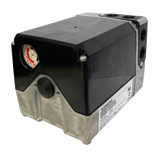
SQM5...
Reversing Actuators
Description
Features
SQM5... reversing actuators are used for the positioning of flow control valves, butterfly
valves, dampers, or any application requiring rotary motion. The SQM5... actuators
accommodate control input signals of 4 to 20 mA, 0 to 135 , 0 to 10 Vdc, 0 to 20 mA,
position proportional and floating control. The available output signals include
4 to 20 mA, 0 to 135 , 0 to 10 Vdc, 0 to 20 mA, and 0 to 1000 . SQM5... actuators
are available with up to six internal, easily adjustable switches.
A selection of exchangeable circuit boards provide a variety of functions including
auto/manual selector switch, manual forward/reverse toggle switch, zero and span
adjustment, parallel or master/slave operation, split range control, input signal override,
and selectable electronic linearization.
The SQM5... is engineered for precision. It is particularly well suited for applications
requiring a high degree of modulating accuracy and repeatability.
The SQM5... actuator may be mounted in any position. A selection of mounting
brackets and shafts provides installation flexibility and allows for the simple replacement
of most competitive actuators.
•
Two limit switches, plus up to four internal auxiliary switches
•
Fully closed "economy position" switch
•
Drive shaft and cam drum disengagement clutches
•
Auto/manual switch, manual control forward/reverse toggle switch
•
UL, CSA approved 24 and 110 Vac versions
•
CE approved 220 Vac versions
•
Field reversible clockwise (cw) or counterclockwise (ccw) operation
•
Various torque ratings and running times available
•
Selection of field exchangeable single-ended and dual-ended shafts
•
Mounting brackets to replace competitive actuators
Technical Instructions
Document No. 155-517P25
Siemens Building Technologies, Inc.
Jan 25, 2022
Advertisement
Table of Contents

Related Manuals for Siemens SQM50.484R8A


Summary of Contents for Siemens SQM50.484R8A
- Page 1 CE approved 220 Vac versions • Field reversible clockwise (cw) or counterclockwise (ccw) operation • Various torque ratings and running times available • Selection of field exchangeable single-ended and dual-ended shafts • Mounting brackets to replace competitive actuators Siemens Building Technologies, Inc.
-
Page 2: Application
In all applications, commissioning is simplified. Shaft and cam drum disengagement clutches allow for the quick manual alignment of the actuator shaft and switch cams. The forward/reverse toggle switch in combination with the auto/manual selector switch provides direct manual control. Page 2 Siemens Building Technologies, Inc. -
Page 3: Table Of Contents
Reversing Rotational Direction Page 18 Shaft Installation Page 20 Circuit Board Installation Page 20 AGA56.41/42/43… Page 20 AGA56.9A Page 22 AGA56.1A97 Page 24 Potentiometer Removal/Installation Page 25 Specification Data Page 26 Dimensions Page 29 Siemens Building Technologies, Inc. Page 3... - Page 4 SQM50.464R1A3 SQM50.464R1A3R SQM50.464R1G3 SQM50.464R2G3 SQM50.484R8G3 SQM50.464R1G4 SQM50.464R1G3R SQM50.464R2G3R SQM50.464R1G7 SQM50.464R1G7R SQM50.464R1H3 SQM50.484R8H3 SQM50.464R1H3R SQM50.464R1Z3 SQM50.464R2Z3 SQM50.484R8Z3 SQM50.464R1Z3R SQM50.467R1Z3R SQM53.461R1Z3 SQM53.464R1A SQM53.464R1A3 SQM53.464R1G3 SQM53.464R1G7 SQM53.464R1G7R SQM53.464R1Z3 SQM53.464R2Z3 SQM53.467R1Z3 SQM53.467R1Z3R SQM53.467R2A3 SQM56.564R1A SQM56.564R1G4 SQM56.564R1G7 SQM56.564R1H4 SQM56.564R1Z3 Page 4 Siemens Building Technologies, Inc.
-
Page 5: Actuators
ASZ16.733 135, 135° (wire wound) adaptable to Eclipse butterfly valves. ASZ66.733 135/135, double potentiometer 135° (wire ASK33.9 mounting kit for direct attachment to Siemens wound) VKF41... butterfly valve. (Shaft AGA58.1 required) Additional potentiometer models available. See Siemens technical data sheet 7921. -
Page 6: Sqm5
Rotational direction (Product numbers ending without R are ccw) Clockwise (when facing gear end. See Figure 6 .) Shaft seal (Only available with AGA58.4 3/8 inch square shaft) Blank No shaft seal kit provided Shaft seal kit AGA55.5 installed on actuator Page 6 Siemens Building Technologies, Inc. -
Page 7: Installation And Operating Instructions
7. Line up the “shaft key” with the key slot on the “gear end” of the actuator and slide the shaft until the “insert end” is completely through the brass bushing. 8. Place the second washer onto the “insert end” of the shaft. Using spreading pliers, install the “C” clip. Siemens Building Technologies, Inc. Page 7... -
Page 8: Rotational Direction Verification
The double switch cam pointers are used together with the red scales when configured for clockwise (cw) operation. The individual switch cams can be adjusted by hand or with the use of the tool attached to the outside of the hinged switch terminal protection lid. Page 8 Siemens Building Technologies, Inc. -
Page 9: Shaft Adjustment
To avoid electro-magnetic interference, the SQM5… actuators must be grounded. The ground terminal is located to the right of the auto/manual switch. Disconnect the circuit board wire marked 51 during high voltage testing. Reconnect it to the grounding terminal after the test. Siemens Building Technologies, Inc. Page 9... -
Page 10: Wiring Connections
5. Connect line voltage to terminal Z to drive the actuator in the closing direction. CAUTION: Do not power terminals A and Z simultaneously. Actuator damage will occur. Figure 7. Basic Functional Diagram of AGA56.1… Page 10 Siemens Building Technologies, Inc. -
Page 11: Aga56.41/42/43
Connect line voltage to terminal Z to drive the actuator to the fully closed/economy position (switch II). Connect the input control signal wires to the appropriate terminals. See Figure 9. CAUTION: Do not power terminals A and Z simultaneously. Actuator damage will occur. Siemens Building Technologies, Inc. Page 11... - Page 12 SQM5… Reversing Actuators Technical Instructions Document No. 155-517P25 Jan 25, 2022 Wiring, Continued Figure 9. Basic Functional Diagram of AGA56.4… Figure 10. AGA56.41/42/43… Terminal and Trim Potentiometer Boards. Page 12 Siemens Building Technologies, Inc.
-
Page 13: Aga56.9
8. Connect line voltage to terminal Z to drive the actuator to the fully closed/economy position (switch II). 9. Connect the input control signal wires to the appropriate terminals. See Figure 11. CAUTION: Do not power terminals A and Z simultaneously. Actuator damage will occur. Siemens Building Technologies, Inc. Page 13... - Page 14 SQM5… Reversing Actuators Technical Instructions Document No. 155-517P25 Jan 25, 2022 Wiring, Continued Figure 11. Basic Functional Diagram of AGA56.9… Figure 12. AGA56.9… Terminal and Trim Potentiometer/Jumper Board. Page 14 Siemens Building Technologies, Inc.
-
Page 15: Modulation Adjustment
MIN and MAX trim potentiometers are set inside the setting range of switch cams I and III. See the example in Figure 13. Figure 13. Switch Cam and Trim Potentiometer Setting. Siemens Building Technologies, Inc. Page 15... -
Page 16: Cover Installation
4 to 20 mA (Signal from U3, common to M) • 0 to 10Vdc (Signal from U1, common to M) • 0 to 20mA (Signal from U2, common to M) Double potentiometers ASZ22… provide additional output signals. Page 16 Siemens Building Technologies, Inc. - Page 17 U4 and Y0.) See Figure 16. NOTE: It is possible to configure the actuator for split range operation 12 to 4 mA and 20 to 12 mA. Consult your authorized Siemens Building Technologies combustion products sales representative for details. Figure 16. Split Ranging.
-
Page 18: Sqm5X.xxxxxgx Actuators
This will give easy access to the switch cams and a better view of the cam drum scales. If no potentiometer ASZ… is installed, the reversing procedure is complete. If a potentiometer ASZ… is installed, complete Steps 3 through 9. Page 18 Siemens Building Technologies, Inc. - Page 19 For counterclockwise rotation, manually rotate the potentiometer gear until the white line next to the “1” mark on the potentiometer gear face is exactly in alignment with the potentiometer gear alignment pointer Siemens Building Technologies, Inc. Page 19...
-
Page 20: Shaft Installation
From the switch housing side of the actuator, guide the base circuit board into the bottom of the circuit board Figure 19. mounting bracket. See Figure 19. Page 20 Siemens Building Technologies, Inc. - Page 21 See Figure 21. Figure 20. Connect the bundled blue, black and brown potentiometer wires to the terminal block located on the ASZ… potentiometer circuit board. See Potentiometer Installation. Figure 21. Siemens Building Technologies, Inc. Page 21...
-
Page 22: Aga56.9A
3. Remove the two upright circuit boards from the mounting bracket by gently pulling aside the vertical supports and sliding the boards upward. Remove the base circuit board from the bottom of the mounting bracket. Discard the shipping mounting bracket. Page 22 Siemens Building Technologies, Inc. - Page 23 “N” to the double terminal block Figure 24. located on the outer end of the switch housing. e. Connect the grounding wire marked "51" to the ground terminal located to the right of the auto/manual switch. Figure 25. Siemens Building Technologies, Inc. Page 23...
-
Page 24: Aga56.1A97
Connect the wire, marked “1” from the circuit board to switch I, terminal 1. b. Connect the wire, marked “2” from the circuit board to switch II, terminal 2. c. Connect the wire, marked “13” from the circuit board to switch III, terminal 13. Page 24 Siemens Building Technologies, Inc. -
Page 25: Potentiometer Removal/Installation
Align scale position “0” on the actuator position indicating dial with the dial pointer by rotating the dial in the clockwise direction to avoid loosening the potentiometer gear attachment screw. See Figure 6. Siemens Building Technologies, Inc. Page 25... -
Page 26: Specification Data
Boards Screwed and spade connectors Dimensions See Figures 28 through 31. Weight 7.3 lb (3.3 kg) Housing Aluminum pressure die casting Enclosure (cover) Lexan Motor Lock resistant Disengagements Manual for drive and cam shaft Page 26 Siemens Building Technologies, Inc. - Page 27 Manual toggle switch 3-position switch Weight 0.7 lb (0.33 kg) AGA56.42A… Electronic circuit boards Same specifications as AGA56.41A except Input signal 0 to 135 ohm Impedance 300 Current input AGA56.42A… 100K Voltage input Siemens Building Technologies, Inc. Page 27...
- Page 28 ASZ... Potentiometers Manual toggle switch 3-position switch Weight 0.7 lb (0.33 kg) ASZ... Potentiometers Versions Single and double potentiometer Resistor values See Table 2 and Data Sheet 7921. Hysteresis < 0.3% related to drive shaft Page 28 Siemens Building Technologies, Inc.
-
Page 29: Dimensions
SQM5… Reversing Actuators Technical Instructions Document No. 155-517P25 Jan 25, 2022 Dimensions The first dimension given is measured in inches. Millimeters are shown in parentheses. Figure 28. SQM5x.xxxRxx Dimensions. Siemens Building Technologies, Inc. Page 29... - Page 30 SQM5… Reversing Actuators Technical Instructions Document No. 155-517P25 Jan 25, 2022 Dimensions, Continued Figure 29. Mounting Bracket AGA57.3. Figure 30. AGA57.4 Mounting Bracket. Page 30 Siemens Building Technologies, Inc.
- Page 31 Information in this publication is based on current specifications. The company reserves the right to make changes in specifications and models as design improvements are introduced. Other product or company names mentioned herein may be the trademarks of their respective owners. © 2022 Siemens Building Technologies, Inc. Siemens Building Technologies, Inc.
Need help?
Do you have a question about the SQM50.484R8A and is the answer not in the manual?
Questions and answers