Siemens SQM5 Series Technical Instructions
Reversing actuators
Hide thumbs
Also See for SQM5 Series:
- Technical instructions (31 pages) ,
- Operation (5 pages) ,
- Technical instructions (31 pages)
Table of Contents
Advertisement
Quick Links
Download this manual
See also:
Technical Instructions
SQM5...
Reversing Actuators
ISO 9001
REGISTERED FIRM
Description
Features
®
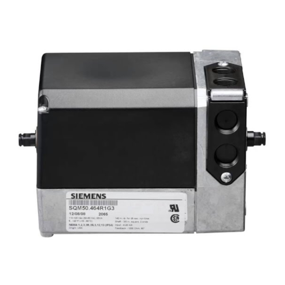
SQM5... reversing actuators are used for the positioning of flow control valves, butterfly
valves, dampers, or any application requiring rotary motion. The SQM5... actuators
accommodate control input signals of 4-20 mA, 0-135 Ω, 0-10 Vdc, 0-20 mA, position
proportional and floating control. The available output signals include 4-20 mA,
0-135 Ω, 0-10 Vdc, 0-20 mA, and 0-1000 Ω. SQM5... actuators are available with up to
eight internal, easily accessible and adjustable auxiliary switches.
A selection of exchangeable circuit boards provide a variety of functions including
auto/manual selector switch, manual forward/reverse toggle switch, zero and span
adjustment, parallel or master/slave operation, split range control, input signal override,
and selectable electronic linearization.
The SQM5... is engineered for precision. It is particularly well suited to applications
requiring a high degree of modulating accuracy and repeatability. Drive shaft play is
limited to 0.3° with a modulating accuracy of 250 repositions through 90° of travel.
The SQM5... actuator may be mounted in any position. A selection of mounting
brackets and shafts provide installation flexibility and allow for the simple replacement of
most competitive actuators.
•
Modulating accuracy of 250 repositions through 90°
•
Two limit switches, plus up to six internal auxiliary switches
•
Full closed "economy position" switch
•
Drive shaft and cam drum disengagement clutches
•
Auto/manual switch, manual control forward/reverse toggle switch
•
UL, CSA and CE approved 24, 110 and 220 Vac versions
•
Field reversible clockwise (cw) or counterclockwise (ccw) operation
•
Various torque ratings and running times available
•
Selection of field exchangeable one and two ended shafts
•
Mounting brackets to replace competitive actuators
Technical Instructions
Document No. 155-517P25
Rev. 1, July, 2000
Siemens Building Technologies, Inc.
Advertisement
Table of Contents

Subscribe to Our Youtube Channel
Related Manuals for Siemens SQM5 Series


Summary of Contents for Siemens SQM5 Series
- Page 1 UL, CSA and CE approved 24, 110 and 220 Vac versions • Field reversible clockwise (cw) or counterclockwise (ccw) operation • Various torque ratings and running times available • Selection of field exchangeable one and two ended shafts • Mounting brackets to replace competitive actuators Siemens Building Technologies, Inc.
-
Page 2: Table Of Contents
Reversing Rotational Direction Page 16 Shaft Installation Page 17 Circuit Board Installation Page 17 AGA56.41/42/43… Page 18 AGA56.9A Page 19 AGA56.1A97 Page 21 Potentiometer Removal/Installation Page 22 Specification Data Page 23 Dimensions Page 26 Page 2 Siemens Building Technologies, Inc. - Page 3 1. Torque will vary with the selection of the shaft. See Specifications. 2. Running time for 135° ➔ multiply by 1.5 For 50 Hz ➔ multiply by 1.2 3. SQM5x.xxxxxZx models also accept a 0-20 mA input signal. Siemens Building Technologies, Inc. Page 3...
- Page 4 , 135° adaptable to Eclipse butterfly valves. Ω ASZ22.803 1000/1000 double potentiometer, 90° ASK33.9 mounting kit for direct attachment to Siemens Ω ASZ22.833 1000/1000 double potentiometer, 135° VKF41... butterfly valve. (Shaft AGA58.1 required) Additional potentiometer models available. See Siemens technical data sheet 7921.
-
Page 5: Sqm5
7 ASZ22.803 (1000/1000 Ohm, 90°) 8 ASZ22.833 (1000/1000 Ohm, 135°) Rotational Direction (if no R, rotation is ccw) R Clockwise (when facing gear end. See Figure 6 .) Figure 1. SQM5… Product Number Identification Legend. Siemens Building Technologies, Inc. Page 5... -
Page 6: Installation And Operating Instructions
WASHERS Figure 5. 7. Line up the “shaft key” with the key slot on the “gear end” of the actuator and slide the shaft until the “insert end” is completely through the brass bushing. Page 6 Siemens Building Technologies, Inc. -
Page 7: Rotational Direction Verification
The double switch cam pointers are used together with the red scales when configured for clockwise (cw) operation. The individual switch cams can be adjusted by hand or with the use of the tool attached to the outside of the hinged switch terminal protection lid. Siemens Building Technologies, Inc. Page 7... -
Page 8: Shaft Adjustment
3. Connect line voltage to terminal A to drive the actuator in the opening direction. 4. Connect line voltage to terminal Z to drive the actuator in the closing direction. Page 8 Siemens Building Technologies, Inc. -
Page 9: Aga56.41/42/43
Z, ZL, A or 13. However, terminal LR must be powered once Z, ZL, A and 13 are no longer powered and modulating operation is required (refer to application guide for typical installation examples). 5. Connect the input control signal wires to the appropriate terminals. Siemens Building Technologies, Inc. Page 9... - Page 10 12 22 13 23 Figure 9. Basic Functional Diagram of AGA56.4… OPE MAX MIN OPE MAX MIN MAN. MAN. AUTO. AUTO. AGA56.42A... AGA56.41A... OPE MAX MIN MAN. AUTO. AGA56.43A... Figure 10. AGA56.41/42/43… Terminal/Trim Potentiometer Boards. Page 10 Siemens Building Technologies, Inc.
-
Page 11: Aga56.9
0...2 V 0...10 V 0...20 mA 4...20 mA 0...3 U1..3 SW 2 AUTO maximum "economy" minimum IV...VIII auxilliary ASZ... (1000 Ohm) 11 21 12 22 13 23 Figure 11. Basic Functional Diagram of AGA56.9… Siemens Building Technologies, Inc. Page 11... -
Page 12: Commissioning
See Figures 10 and 12. Set the OPE/MAX/MIN slide switch to “MAX”. The blue MAX trim potentiometer can now be gently adjusted to the required maximum position. Return the OPE/MAX/MIN slide switch to OPE. Page 12 Siemens Building Technologies, Inc. -
Page 13: Position Indicating Dial Adjustment
Lift the two screws on the cover corners and slide the cover end into the groves at the gear end of the actuator. See Figure 14. Press the cover into place and then press the screws inward and tighten. See Figure 15. Figure 14. Figure 15. Siemens Building Technologies, Inc. Page 13... -
Page 14: Sqm5X.xxxxxzx Actuators
If no signal is present on Y0, Y1, Y2 or Y3, the actuator will modulate through the full rotational range in response to a 12 to 20 mA signal applied at ZF. If a Page 14 Siemens Building Technologies, Inc. -
Page 15: Sqm5X.xxxxxgx Actuators
See Figure 16. NOTE: It is possible to configure the actuator for split range operation 12 to 4 mA and 20 to 12 mA. Consult your authorized Siemens Building Technologies combustion products sales representative for details. 25% 50% 75% MAX 0...3... -
Page 16: Sqm5X.xxxxxax Actuators
ATTACHMENT SCREW ATTACHMENT SCREW Figure 17. Reversing Rotational Direction on the ASZ Potentiometer Board. 5. See Figure 17. Disconnect the blue and brown wires from the terminal block located on the ASZ… potentiometer circuit board. Page 16 Siemens Building Technologies, Inc. -
Page 17: Shaft Installation
Gently pull the capacitor forward until it unclips and temporarily place it on top of CAPACITOR the gear housing. See Figure 18. Figure 18. CAUTION: Do not disconnect any capacitor wiring. Siemens Building Technologies, Inc. Page 17... -
Page 18: Aga56.41/42/43
See Figure 21. 8. Connect the bundled blue, black and brown potentiometer wires to the terminal block located on the ASZ… potentiometer circuit board. See Potentiometer Installation. Figure 21. Page 18 Siemens Building Technologies, Inc. -
Page 19: Aga56.9A
3. Remove the two upright circuit boards from the mounting bracket by gently pulling aside the vertical supports and sliding the boards upward. Remove the base circuit board from the bottom of the mounting bracket. Discard the shipping mounting bracket. Siemens Building Technologies, Inc. Page 19... - Page 20 Connect the gray grounding wire marked "51" to the ground terminal located to the right of the auto/manual switch. Figure 25 Page 20 Siemens Building Technologies, Inc.
-
Page 21: Aga56.1A97
Connect the black wire, marked “1” from the circuit board to switch I, terminal 1. b. Connect the yellow wire, marked “2” from the circuit board to switch II, terminal 2. c. Connect the brown wire, marked “13” from the circuit board to switch III, terminal Siemens Building Technologies, Inc. Page 21... -
Page 22: Potentiometer Removal/Installation
Align scale position “0” on the actuator position indicating dial with the dial pointer by rotating the dial in the clockwise direction to avoid loosening the potentiometer gear attachment screw. See Figure 6. Page 22 Siemens Building Technologies, Inc. -
Page 23: Specification Data
Boards Screwed and spade connectors Dimensions See Figures 28 through 31. Weight 7.3 lbs. (3.3 kg) Housing Aluminum pressure die casting Enclosure (cover) Lexan Motor Lock resistant Disengagements Manual for drive and cam shaft Siemens Building Technologies, Inc. Page 23... - Page 24 2-position switch Manual toggle switch 3-position switch Weight 0.7 lb. (0.33 kg) AGA56.42A… AGA56.42A… Electronic circuit boards Same specifications as AGA56.41A except Input signal 0-135 Ohm Impedance ≤300 Ω Current input ≥100kΩ Voltage input Page 24 Siemens Building Technologies, Inc.
- Page 25 Manual toggle switch 3-position switch Weight 0.7 lb. (0.33 kg) ASZ... Potentiometers ASZ... Potentiometers Versions Single and double potentiometer Resistor values See Table 2 and data sheet 7921. Hysteresis < 0.3 % related to drive shaft Siemens Building Technologies, Inc. Page 25...
-
Page 26: Dimensions
COVER REMOVAL 1-3/16 1-7/16 (30) 5-1/4 (36) (133) (10) 2-5/8 (67) 7-1/16 (180) 7-1/16 (180) 1/16 (3.5) 4-7/16 1/4"-20 3 -1/8 (113) (80) 5-3/16 (132) 6-7/16 (164) 5/16 5/16 (8.5) (7.5) Figure 28. SQM5x.xxxRxx Dimensions. Page 26 Siemens Building Technologies, Inc. - Page 27 (80) 2-3/8 5/16 2-1/2 (60.4) (8.73) (63.5) 5/16 (7.94) 2-3/8 1-11/16 (60.64) (50.8) (43) 1-5/8 1-1/2 (42) (38.1) (12.5) 13/16 13/16 (20.3) (20.3) All non-sized holes O 5/16 (7.62) Figure 30. AGA57.4 Mounting Bracket. Siemens Building Technologies, Inc. Page 27...
- Page 28 Information in this publication is based on current specifications. The company reserves the right to make changes in specifications and models as design improvements are introduced. © 2000 Siemens Building Technologies, Inc. Your feedback is important to us. If you have Document No.
Need help?
Do you have a question about the SQM5 Series and is the answer not in the manual?
Questions and answers