LOVATO ELECTRIC DCRL3 Instruction Manual
Automatic power factor controller
Hide thumbs
Also See for DCRL3:
- Instruction manual (28 pages) ,
- Installation manual (9 pages) ,
- Instruction manual (19 pages)
Advertisement
Quick Links
LOV TO ELECTRIC S.P. .
24020 GORLE (BERG MO) IT LI
VI DON E. M ZZ , 12
TEL. 035 4282111
L
E
E-mail info@
ovato
lectric.com
L
E
Web
www.
ovato
lectric.com
W RNING!
– Carefully read the manual before the installation or use.
– This equipment is to be installed by qualified personnel, complying to current standards, to avoid
damages or safety hazards.
– Before any maintenance operation on the device, remove all the voltages from measuring and supply inputs and short-
circuit the CT input terminals.
– The manufacturer cannot be held responsible for electrical safety in case of improper use of the equipment.
– Products illustrated herein are subject to alteration and changes without prior notice. Technical data and descriptions
in the documentation are accurate, to the best of our knowledge, but no liabilities for errors, omissions or
contingencies arising there from are accepted.
–
circuit breaker must be included in the electrical installation of the building. It must be installed close by the
equipment and within easy reach of the operator. It must be marked as the disconnecting device of the equipment:
IEC/EN/BS 61010-1 § 6.11.3.1.
– Clean the device with a soft dry cloth; do not use abrasives, liquid detergents or solvents.
TTENTION !
– Lire attentivement le manuel avant toute utilisation et installation.
– Ces appareils doivent être installés par un personnel qualifié, conformément aux normes en vigueur en
matière d'installations, afin d'éviter de causer des dommages à des personnes ou choses.
–
vant toute intervention sur l'instrument, mettre les entrées de mesure et d'alimentation hors tension et court-circuiter
les transformateurs de courant.
– Le constructeur n'assume aucune responsabilité quant à la sécurité électrique en cas d'utilisation impropre du
dispositif.
– Les produits décrits dans ce document sont susceptibles d'évoluer ou de subir des modifications à n'importe quel
moment. Les descriptions et caractéristiques techniques du catalogue ne peuvent donc avoir aucune valeur
contractuelle.
– Un interrupteur ou disjoncteur doit être inclus dans l'installation électrique du bâtiment. Celui-ci doit se trouver tout
près de l'appareil et l'opérateur doit pouvoir y accéder facilement. Il doit être marqué comme le dispositif d'interruption
de l'appareil : IEC/EN/BS 61010-1 § 6.11.3.1.
– Nettoyer l'appareil avec un chiffon doux, ne pas utiliser de produits abrasifs, détergents liquides ou solvants.
CHTUNG!
– Dieses Handbuch vor Gebrauch und Installation aufmerksam lesen.
– Zur Vermeidung von Personen- und Sachschäden dürfen diese Geräte nur von qualifiziertem
Fachpersonal und unter Befolgung der einschlägigen Vorschriften installiert werden.
– Vor jedem Eingriff am Instrument die Spannungszufuhr zu den Messeingängen trennen und die Stromwandler
kurzschlie en.
– Bei zweckwidrigem Gebrauch der Vorrichtung übernimmt der Hersteller keine Haftung für die elektrische Sicherheit.
– Die in dieser Broschüre beschriebenen Produkte können jederzeit weiterentwickelt und geändert werden. Die im
Katalog enthaltenen Beschreibungen und Daten sind daher unverbindlich und ohne Gewähr.
– In die elektrische nlage des Gebäudes ist ein usschalter oder Trennschalter einzubauen. Dieser muss sich in
unmittelbarer Nähe des Geräts befinden und vom Bediener leicht zugänglich sein. Er muss als Trennvorrichtung für das
Gerät gekennzeichnet sein: IEC/EN/BS 61010-1 § 6.11.3.1.
– Das Gerät mit einem weichen Tuch reinigen, keine Scheuermittel, Flüssigreiniger oder Lösungsmittel verwenden.
DVERTENCI
– Leer atentamente el manual antes de instalar y utilizar el regulador.
– Este dispositivo debe ser instalado por personal cualificado conforme a la normativa de instalación
vigente a fin de evitar daños personales o materiales.
–
ntes de realizar cualquier operación en el dispositivo, desconectar la corriente de las entradas de alimentación y
medida, y cortocircuitar los transformadores de corriente.
– El fabricante no se responsabilizará de la seguridad eléctrica en caso de que el dispositivo no se utilice de forma
adecuada.
– Los productos descritos en este documento se pueden actualizar o modificar en cualquier momento. Por consiguiente,
las descripciones y los datos técnicos aquí contenidos no tienen valor contractual.
– La instalación eléctrica del edificio debe disponer de un interruptor o disyuntor. Éste debe encontrarse cerca del
dispositivo, en un lugar al que el usuario pueda acceder con facilidad. demás, debe llevar el mismo marcado que el
interruptor del dispositivo (IEC/EN/BS 61010-1 § 6.11.3.1).
– Limpiar el dispositivo con un trapo suave; no utilizar productos abrasivos, detergentes líquidos ni disolventes.
A
71+ .! ,+5+-*P ,-+K/P/! *!F 5 K*!/! -!#0(7/+- %*./ (+1 / ,+0F:1 /
A
/+ 5 R:5!*: .): %*./ (+1 / '1 (%"%'+1 *: ,- +1*: % 1 .+0( 0 . ,( /*G)% ,R! ,%.4 *+-) )% ,-+ ,R! $75!*:
>- 5U +.+ K% ,+E'+5!*: 1P :
A
R! & 'G)'+(% 57. $!) + ,R:./-+&! + ,+&/! )PR% : * ,7&! : 1./0,4 + * ,P/: 5'- /0&/! /- *."+-)7/+-4 ,-+0 0
A
G-+ ! *!*!.! + ,+1P *+./ 5 !(!'/-% '+0 !5,!K*+./ 1 ,R:, P *!1$+ *9$+ ,+0F:17*: -!#0(7/+-0
A
G-+ '4 ,+,. *9 1 /+)/+ +'0)!*/0 )+$+0 ' 4'+(% ,-+&:/ >,- 1 )% K% (E:) 1G1+&!) +,%.4 > &! 01! !*9 1 ' / (+#0
*!) &: ,-+/+ F7 *+0 .)(01*: $+ *+/0
A
,:* K K% + ,+&+1 K &! *0/*+ 5 0 +1 / + !(!'/-% '9$+ -+51+ 0 1 0 +1P 0.!&: G/ * %*./ (+1 *9 1 /P.*9 (:5'+./% ,R:./-+&!
.* *+ +./0,*9 ,- +1*:'0 + .(0$4 ! *0/*+ $+ +5* K%/ & '+ 14,:* : 5 R:5!*: ,R:./-+&!
A
R:./-+& K%./P/! )P''+0 0/P-'+0 *!,+0F:1!&/! - 5%1*: ,-+ 0'/4 /!'0/7 K%./% ( K% -+5,+0E/P (
A
%/%T% 0 /!*T%! ) *0 (0( ;* %*/! ! %*./ ( -! . 0 0/%(%5 -!
A
!./ ! $%, )!*/ 1 "% %*./ ( / ! ,!-.+* ( (%"% / ;* +*"+-)%/ /! 0 ./ * - !(! /0 (! ,!*/-0 !1%/
!/!-%+-M-% . 0 ,!-% +(!(!
A B* %*/! ! !"! /0 -! +-% M-!% +,!- T%0*% ! ;*/-!T%*!-! .0,- %.,+5%/%10(0% ;* !,M-/ T% /+ /! /!*.%0*%(! ! ( %*/-M-%(! !
)M.0- -! I% ! (%)!*/ -! I% . 0-/ %- 0%/ T% +-*!(! ! %*/- -!
A
-+ 0 M/+-0( *0 ,+ /! "% +*.% !- / -!.,+*. %( ,!*/-0 .%#0- *T !(! /-% M ;* 5 ! 0/%(%5 -! %* +-! /M ! $%, )!*/0(0%
A
-+ 0.!(! %(0./- /! ;* ,-!5!*/0( .0*/ .0,0.! )+ %"% M-%(+- I% . $%) M-%(+- "M-M *+/%"% -! */!-%+ -M
%* + 0)!*/ T%! .0*/ ,-! %.! ;* )M.0- 0*+I/%*T!(+- *+ ./-!
!1!*%)!*/!(! *!,-!1M50/! -! , -
0-) -!
!./+-
A
-! 0%! %* (0. 0* %.&0* /+- ;* %*./ ( T% !(! /-% M
(M %-%%
!.% %(M +,!- /+-0(0%
!./ /-! 0%! ) - /
"%%* %.,+5%/%10( ! ! +*! / -! ( ! $%, )!*/0(0%
@
A
0-MT T% %*./-0)!*/0( 0 0* ) /!-% ( /!3/%( )+ (! I% 0. / *0 0/%(%5 T% .0 ./ *T! - 5%1! !/!-#!*T% (% $%5% . 0 .+(1!*T%
@
/!(! /!$*% ! I% !. -%!-%(!
- *0 .!
!,/M *% %+ -M.,0* !-! ,!*/-0 !-+-%(! +)%/!-%(! . 0
!./ /-! 0%! %*./ ( / ,-+ ,! ! ! $%, )!*/ I% ;*/- + 5+*M 0I+-
GB
UTOM TIC POWER F CTOR CONTROLLER
Instructions manual
DCRL3 - DCRL5
TTENZIONE!
– Leggere attentamente il manuale prima dell'utilizzo e l'installazione.
– Questi apparecchi devono essere installati da personale qualificato, nel rispetto delle vigenti normative
impiantistiche, allo scopo di evitare danni a persone o cose.
– Prima di qualsiasi intervento sullo strumento, togliere tensione dagli ingressi di misura e di alimentazione e
cortocircuitare i trasformatori di corrente.
– Il costruttore non si assume responsabilità in merito alla sicurezza elettrica in caso di utilizzo improprio del dispositivo.
– I prodotti descritti in questo documento sono suscettibili in qualsiasi momento di evoluzioni o di modifiche. Le
descrizioni ed i dati a catalogo non possono pertanto avere alcun valore contrattuale.
– Un interruttore o disgiuntore va compreso nell'impianto elettrico dell'edificio. Esso deve trovarsi in stretta vicinanza
dell'apparecchio ed essere facilmente raggiungibile da parte dell'operatore. Deve essere marchiato come il dispositivo
di interruzione dell'apparecchio: IEC/EN/BS 61010-1 § 6.11.3.1.
– Pulire l'apparecchio con panno morbido, non usare prodotti abrasivi, detergenti liquidi o solventi.
UW G !
A
-5! 0V4 %!) % %*./ ( &N 0-5N 5!*% * (!V4 02 V*%! ,-5! 54/ J *%*%!&.5N %*./-0' &O
A
!(0 0*%'*%O % + - V!Q +.< (0 0.5'+ 5!*% )%!*% /!#+ /4,0 0-5N 5!*% )0.5N 4J %*./ (+2 *! ,-5!5
24'2 (%"%'+2 *4 ,!-.+*!( 5#+ *%! 5 + +2%N50&N 4)% ,-5!,%. )%
A
-5! -+5,+ 5O %!) & '% $'+(2%!' ,- * 0-5N 5!*%0 * (!V4 + DN 54J * ,%O %! + 2!&SJ ,+)% -+24 $ % 5 .%( *% +- 5 5!2-5!J
5 %.'% ,-5!'D *%' ,-N +2!#+
A
-+ 0 !*/ *%! ,-54&)0&! * .%! %! + ,+2%! 5% (*+S % 5 !5,%! 5!Q./2+ !(!'/-4 5*! 2 ,-54, '0 *%!2D S %2!#+ 0V4/'+2 *%
0-5N 5!*%
A
-+ 0'/4 +,%. *! 2 *%*%!&.54) +'0)!* %! )+#N 4J 2 ' V !& $2%(% 0 +.'+* (+*! (0 5)+ 4"%'+2 *! ,%.4 +- 5 *!
' / (+#+2! *%! )+#N )%!J 2 52%N5'0 5 /4) V *!& 2 -/+S % 0)+2*!&
A
%*./ ( &% !(!'/-4 5*!& 0 4*'0 * (!V4 025#(O *%J ,-5!DN 5*%' (0 24DN 5*%' 0/+) /4 5*4 +2%*%!* +* 5* & +2 J .%O 2
(%.'%) .N.%! 5/2%! 0-5N 5!*% % 4J D /2+ +.%N# (*4 ,-5!5 +,!- /+-
24DN 5 *% 0-5N 5!*%
A
-5N 5!*%! * (!V4 54S %J )%O''N .5) /'N *%! ./+.+2 J S-+ '+2 S %!-*4 $ ,D4**4 $ !/!-#!*/+2 (0 -+5,0.5 5 (*%'+2
A [ncdbc ucj mnfopqm^py h jlkp^dq fif zhomiq^p^tff qopnlgop`^ `kfj^pciykl lek^hljypcoy o lbcnd^kfcj
k^opl|wcal nqhl`lbop`^
A Xl fe_cd^kfc pn^`j fif j^pcnf^iyklal qwcn_^ jlkp^d blidck oqwcop`i|pyo| pliyhl h`^ifrftfnl`^kkxj mcnolk^ilj
` ollp`cpop`ff o bcgop`q{wfjf klnj^pf`^jf
A [cncb mnl`cbckfcj i{_xs n^_lp ml pcskfucohljq l_oiqdf`^kf{ qopnlgop`^ kcl_slbfjl l_coplufpy `oc
fejcnfpciykxc f mfp^{wfc `slbkxc hlkp^hpx ^ p^hdc e^jhkqpy k^hlnlphl `slbkxc hlkp^hpx pn^korlnj^pln^ plh^ \\
A [nlfe`lbfpciy kc kcocp lp`cpop`ckklopy e^ l_comcuckfc zichpnl_celm^oklopf ` oiqu^c kck^bicd^wcal fomliyel`^kf|
qopnlgop`^
A Yebcif| lmfo^kkxc ` k^opl|wcj blhqjckpc ` i{_lg jljckp jlaqp mlb`cnakqpyo| fejckckf|j fif
qol`cnvckop`l`^kf|j [lzpljq h^p^ildkxc b^kkxc f lmfo^kf| kc jlaqp n^ooj^pnf`^pyo| h^h bcgop`fpciykxc o pluhf
enckf| hlkpn^hpl`
A ]ichpnfucoh^| ocpy eb^kf| blidk^ _xpy lok^wck^ ^`plj^pfucohfj `xhi{u^pcicj hlplnxg blidck _xpy n^omlildck
`_ifef l_lnqbl`^kf| ` mncbci^s blopqm^ lmcn^pln^ W`plj^pfucohfg `xhi{u^pciy blidck _xpy mnlj^nhfnl`^k h^h
lphi{u^{wcc qopnlgop`l l_lnqbl`^kf|
A Zufophq qopnlgop`^ mnlfe`lbfpy o mljlwy{ j|ahlg oqslg ph^kf _ce mnfjckckf| ^_n^ef`kxs j^pcnf^il` dfbhfs
jl{wfs oncbop` fif n^op`lnfpcicg
A
+*/ & 1! '0(( *C) * =* ! 0 !( '%/ C*C %'' /(% ! +'040*05
A
0 , - /( - '%I%(!-! 1!4 *!.*!(!-! 5 - - 1!-)! %$/%) (%*! ' -IC 4?-?-(?'/! +( * .%./!) '0-) *+-)( -C* #=-!
' (%"%4! ,!-.+*!( / - "C* * )+*/! ! %()!(% %-(!-
A
, - /
%$ 5 $!-$ *#% %- )? $ (! ! 0(0*)
!1-! 4 ,/C-C*C5
A 6-!/% % , - /C* $ / (C '0(( *C)C* * ' 4* '( * * !(!'/-%'.!( #?1!*(%H! %/ .+-0)(0(0' ' 0( !/)!5
A
0 +'?) * / -%" ! %(!* ?-?*(!- $!- * !1-%)(!-! 1!4 !H%I%)(!-! 8C'/C- 0 .! !,(! ' / (+# '% / -%" 1! !H!-(!- $!-$ *#% %-
H( 4C C !H!-% $ %5 !H%( %-
A
%* *C* !(!'/-%' .%./!)%* ! %- * $/ - 1!4 I (/!- 0(0*) (C C- 0 * $/ - 1!4 I (/!- +,!- /=-?* '+( 4(C'( 0( I %(! !H% 4 'C*
%- 4!- ! +() (C C- , - /C %$ 5 !1-! !* 8C' -/) #=-!1% 4 , * 0 * $/ - 1!4 I (/!-%* ) -' .C
@
A
, - /C %$ 5 .C1C !/!-& * 1!4 .+(1!*/ '0(( * - ' 40)0I ' %- !5 %(! .%(%*%5 IC* C-C C /!)%5(%' ?-?*(!-% '0(( *) 4C*C5
A
-%&! %*./ ( %&! %(% '+-%E/!*& 0-!L & , F(&%1+ ,-+K%/ &/! 0,0/!
A
1 & 0-!L & )+- %*./ (%- /% 0 .'( 0 . 1 F!J%) *+-) ) + 0K!* +.+ ' '+ % .! %5 &!#(! E/!/! %(% .%#0-*+.*!
+, .*+./%
A
-%&! %(+ ' '1+# 5 $1 / * 0-!L &0 +/,+&%/! * , & *&! . )&!-*%$ % * , & &0J%$ 0( 5 % '- /'+ .,+&%/! 0( 5*! ./!5 (&'! ./-0&*+#
/- *."+-) /+-
A
-+%51+L K *! .*+.% + #+1+-*+./ 5 !(!'/-%K*0 .%#0-*+./ 0 .(0K &0 *!,- 1%(*+# '+-%E/!*& +,-!)!
A
1 &! ,-%' 5 * 0-!L & ,-! )!/ &! ./ (*+# 0. 1-E 1 *& % ,-+)&!* !5 ,-!/$+ *! * & 1! !$*%K'% ,+
.0 /+K*% (% *! ,-!05%) )+ + #+1+-*+./ 5 )+F! %/*! *!* )&!-*! #-!E'!
A
!(!'/-%K*0 %*./ ( %&0 5#- ! )+- %/% %*./ (%- * ,-!'% K * )+- %/% %*./ (%- * (%50 0-!L & % * +$1 / -0'! +,!- /!- /!
+5* K!* ' + - ./ 1(& K 0 .'( 0 . *+-)+)
A
-!L & K%./%/! . )!'+) .0$+) '-,+) !5 ,-%)&!*! - 5%1 /!'0J%* +/ , ( %(% !/!- F!*/
0.% 4J +5* 5+*4 & '+ 0-5N 5!*%! .D0VN ! +
@
@
* =* ! =(8?) #%-%I(!-%* !'% #!-%(%)% '!.%, 'C) /- *."+-) /=-(!-%*! ! 'C.
@
G
B
% % +,%.% 0 +1%) 0,0/ )
1
Advertisement

Related Manuals for LOVATO ELECTRIC DCRL3


Summary of Contents for LOVATO ELECTRIC DCRL3
- Page 1 DCRL3 - DCRL5 W RNING! TTENZIONE! – Carefully read the manual before the installation or use. – Leggere attentamente il manuale prima dell’utilizzo e l’installazione. – This equipment is to be installed by qualified personnel, complying to current standards, to avoid –...
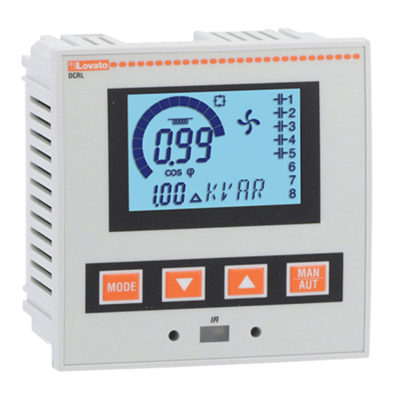
- Page 2 – Flush-mount, standard 96x96mm housing – Backlit LCD screen – Versions: • DCRL3 with 3 relays, expandable to 6 max. • DCRL5 with 5 relays, expandable to 8 max. – 4 navigation keys for function and settings –...
- Page 3 OPER TING MODES There are three possible operating modes, listed below: TEST Mode – When the unit is brand new and has never been programmed, it automatically enters in TEST mode that allows the installer to manually activate the individual relay outputs, so you can verify the correct wiring of the panel –...
- Page 4 ME SURES – The DCRL provides a set of measurements displayed on the alphanumeric display, in conjunction with the current cosphi that is always displayed on the main display – Press the MODE key to scroll through the measures in rotation –...
- Page 5 KEYP D LOCK – function to exclude all modification to operating parameters can be enabled; measurement viewing is still provided in any case – To lock and unlock the keypad, press and keep MODE key pressed. Then press the L key three times and the M key twice and after that release MODE –...
- Page 6 P R METER SETTING WITH PC – You can use the DCRG Remote control software to transfer (previously programmed) setup parameters from the DCRL to the hard drive of the PC and vice versa – The parameter may be partially transferred from the PC to the DCRL, transferring only the parameters of the specified menus. P R METER SETTING (SETUP) FROM FRONT P NEL To access the programming menu (setup): –...
- Page 7 P R METER T BLE – Below are listed all the programming parameters in tabular form. For each parameter are indicated the possible setting range and factory default, as well as a brief explanation of the function of the parameter. The description of the parameter shown on the display can in some cases be different from what is reported in the table because of the reduced number of characters available.
- Page 8 P.11 ... P.18 – Function of output relays 1 ... 8: OFF = Not used. 1 .. 32 = Weight of the step. This relay drives a bank of cpacitors which power is n times (n = 1…32) the smallest power defined with parameter P.06. ON = lways on.
- Page 9 P.21 – If set to OFF, password management is disabled and anyone has access to the settings and commands menu. P.22 – With P.21 enabled, this is the value to specify for activating user level access. See Password access chapter. P.23 –...
- Page 10 L RMS – When an alarm is generated , the display will show an alarm icon, the code and the description of the alarm in the language selected – If the navigation keys in the pages are pressed, the scrolling message showing the alarm indications will disappear momentarily, to reappear again after 30 seconds –...
- Page 11 – For the electrical connections see the wiring diagrams in the dedicated chapter and the requirements reported in the technical characteristics. WIRING DI GR MS W RNING! Disconnect the line and the supply when servicing on terminals. Three-phase standard wiring MAINS DCRL DCRL3 L1 L2 L3 1 2 3 4 DCRL5 INPUT INPUT VOLTAGE...
- Page 12 Single-phase wiring MAINS DCRL DCRL3 1 2 3 4 DCRL5 INPUT INPUT VOLTAGE SUPPLY CURRENT 100-600V 100-440V S1 S2 14 13 6 7 8 9 10 11 12 2x1A 2x1A FU10 LOAD SINGLE-PH SE CONNECTION Wiring configuration for single-phase applications...
- Page 13 TERMIN L POSITION DCRL3 DCRL5 Aux supply Aux supply 100-440V~ 100-440V~ 50/60Hz 50/60Hz 3,5 W 3,5 W 9,5 VA 9,5 VA V Input V Input 100-600V~ 100-600V~ 50/60Hz 50/60Hz MECH NIC L DIMENSIONS ND P NEL CUTOUT [mm] EXP 10...
- Page 14 Power consumption <0.6V WG Range: 18 - 12 WG stranded or solid Relay output: DCRL3 OUT 1 - 2 / DCRL5 OUT 1 - 4 Field Wiring Terminals Tightening Torque: 4.5lb.in Flat panel mounting on a Type 1 enclosure Contact type...
- Page 15 DCRL3 - DCRL5 W RNING! TTENZIONE! – Carefully read the manual before the installation or use. – Leggere attentamente il manuale prima dell’utilizzo e l’installazione. – This equipment is to be installed by qualified personnel, complying to current standards, to avoid –...
- Page 16 & 4 '* -JH7D?97 -JH7D?97 +EL?@;IJ H;L?P?@; FH?HKaD?A7 HPE FEIJ7LB@7D@; JH7DI<EHC7JEH7 /LE: .78B?97 F7H7C;J7H7 *F?I B7HC? !KDA9?@; J?FAELD?9; *F?I 7B7HC7 )7PD7A; D7 P7IBEDK 47:7D7 ILE@IJL7 7B7HC7 )7a?D? H7:7 $P8EHD?A D7H;:8? (@;H;D@7 /FEH787 >7H:L;HIAE= AB@Ka7 2 BEA7:7 J?FAELD?9; /=H7:D@7 +HE[?H?LEIJ ->;C; E]?a;D@7 +H?AB@Ka7A P7 $, FHE=H7C?H7D@;...
- Page 17 ) `$)$ , / D7IJ7LAK I; D78H7@7@K JH? CE=K_7 D7a?D7 H7:7 $=+0 ! ! V +EJFKDE DEL7 @;:?D?97 AE@7 D?@; D?A7: 8?B7 FHE=H7C?H7D7 7KJEC7JIA? KB7P? K D7a?D . -. AE@? ?DIJ7B7J;HK ECE=K_K@; HKaDE 7AJ?L?H7D@; FE@;:?D?> H;B;@D?> ?PB7P7 A7AE 8? I; CE=BE FHEL@;H?J? @; B? FBEa7 FH7L?BDE E]?a;D7 V )7a?D .
- Page 18 (% , )% ,' FHK]7 D?P C@;H;D@7 AE@7 I; FH?A7PK@K D7 IBELDE8HE@a7DEC P7IBEDK K AEC8?D79?@? I JH;DKJ7aD?C 9EI c AE@? @; KL?@;A FH?A7P7D D7 =B7LDEC P7IBEDK V +H?J?ID?J; J?FAK (* A7AE 8?IJ; C@;H;D@?C7 FH;B7P?B? K HEJ79?@? V &7: FHEb; I;AKD:? 7 :7 D?IJ; FH?J?IDKB? D?@;:DK J?FAK P7IBED I; 7KJEC7JIA? LH7_7 D7 P7:7DE C@;H;D@; :;<?D?H7DE F7H7C;JHEC + AE @;...
- Page 19 '*& .$+&*0)$ V (E=K_; @; EIFEIE8?J? <KDA9?@K AE@7 IFH@;a7L7 IL7AK ?PC@;DK H7:D?> F7H7C;J7H7 7 :7 I; C@;H;D@7 ?F7A CE=K FH?A7P7J? V &7AE 8?IJ; 8BEA?H7B? ? :;8BEA?H7B? J?FAELD?9K FH?J?ID?J; ? :H]?J; FH?J?IDKJK J?FAK (* 47J?C JH? FKJ7 FH?J?ID?J; J?FAK L ? :L7 FKJ7 J?FAK M F7 EJFKIJ?J; (* V &7: @;...
- Page 20 +*-. 0'% )% + , ( . , , `/) '*( V -E<JL;HEC ," ,;CEJ; 9EDJHEB CE];J; FH;D?@;J? FH;J>E:DE FHE=H7C?H7D; F7H7C;JH; FEIJ7LB@7D@7 I ,' 7 D7 JLH:? :?IA H7aKD7B7 ? E8HDKJE V +H?@;DEI F7H7C;J7H7 I H7aKD7B7 D7 ,' CE]; 8?J? :@;BEC?a7D J@ I7CE FH?@;DEI F7H7C;J7H7 ?P D7PD7a;D?> ?P8EHD?A7 +*-.
- Page 21 . '$ + , ( . , V / D7IJ7LAK I; D7LE:; IL? F7H7C;JH? FHE=H7C?H7D@7 K E8B?AK J78B?9; 47 IL7A? F7H7C;J7H D7LE:; I; CE=K_? H7IFED FEIJ7LB@7D@7 ? P7:7D; JLEHD?aA; FEIJ7LA; A7E ? AH7JAE E8@7[D@;D@; <KDA9?@; F7H7C;JH7 *F?I F7H7C;JH7 AE@? I; FH?A7PK@;...
- Page 22 V !KDA9?@7 ?PB7PD?> H;B;@7 ); AEH?IJ? I; .;]?D7 IJKFD@7 )7 EL7@ H;B;@ IFE@;D7 @; @;:D7 AED:;DP7JEHIA7 87J;H?@7 a?@7 @; ID7=7 D FKJ7 D D7@C7D@7 ID7=7 :;<?D?H7D7 F7H7C;JHEC + /L?@;A 7AJ?L?H7D B7HC DEHC7BDE D?@; FE8Kb;D ,;B;@ I; FE8KbK@; A7: I; FE@7L? 8?BE AE@? 7B7HC I7 ILE@IJLEC *F_? 7B7HC B7HC @;...
- Page 23 AE @; FEIJ7LB@;D D7 *!! KFH7LB@7D@; BEP?DA7C7 @; ED;IFEIE8B@;DE ? FH?IJKF FEIJ7LA7C7 ? ?P8EHD?AK D7H;:8? @; IBE8E:7D V &7: @; EIFEIE8B@;D + JH;87 D7PD7a?J? ELK LH?@;:DEIJ P7 7AJ?L?H7D@; FH?IJKF7 D7 H7P?D? AEH?ID?A7 0?:@;J? FE=B7LB@; +H?IJKF BEP?DAEC V &7E ? P7 + DE E:DEI? I;...
- Page 24 ' ,($ V &7: :Eb; :E D;AE= 7B7HC7 D7 P7IBEDK I; FH?A7PK@K ?AED7 7B7HC7 [?<H7 ? EF?I 7B7HC7 D7 E:78H7DEC @;P?AK AE FH?J?ID;J; D7L?=79?@IA; J?FA; D7 IJH7D?97C7 FEC?aD? D7JF?I E 7B7HCK JH;DKJDE _; D;IJ7J? ? FEDELDE _; I; FE@7L?J? D7AED I;AKD:? B7HC? I;...
- Page 25 B;AJH?aD; IFE@;L; L?:@;J? D7 I>;C7C7 E]?a;D@7 K FEIL;_;DEC FE=B7LB@K 7 FE=B;:7J? ? P7>J@;L; AE@? I; D7LE:; K J;>D?aA?C A7H7AJ;H?IJ?A7C7 -# ( *\$` )% /+*4*, )% *:IFE@?J; B?D?@K ? D7F7@7D@; FH?B?AEC H7:7 D7 IJ;P7B@A7C7 -J7D:7H:DE JHE<7PDE E]?a;D@; MAINS DCRL DCRL3 L1 L2 L3 1 2 3 4 DCRL5 INPUT INPUT VOLTAGE...
- Page 26 %;:DE<7PDE E]?a;D@; MAINS DCRL DCRL3 1 2 3 4 DCRL5 INPUT INPUT VOLTAGE SUPPLY CURRENT 100-600V 100-440V S1 S2 14 13 6 7 8 9 10 11 12 2x1A 2x1A FU10 LOAD % )*! 4)* -+ % )% &ED<?=KH79?@7 E]?a;D@7 P7 @;:DE<7PD; FH?C@;D;...
- Page 27 +*'*\ % -. 4 '%&$ Aux supply Aux supply 100-440V~ 100-440V~ 50/60Hz 50/60Hz 3,5 W 3,5 W 9,5 VA 9,5 VA V Input V Input 100-600V~ 100-600V~ 50/60Hz 50/60Hz ( # )$`& $( )4$% $ /Z )% +'*` 5CC6 EXP 10...
- Page 28 . #)$`& & , &. ,$-.$& $2$,$0,( 81.$&+,$ )7P?LD? D7FED /I )7P?LD? D7FED ?PEB79?@; /? ,7IFED H7:DE= D7FED7 )7P?LD? FE:DEI?L? ?CFKBID? D7FED /?CF !H;AL;D9?@7 +E:DEI?L? D7FED H7:D; <H;AL;D9?@; FIEH8?H7D7 :?I?F?H7D7 ID7=7 "7,(5+ 1-1.+0( );IJ7D7A D7FED7 ,7:D7 J;CF;H7JKH7 0H?@;C; D;EI@;JB@?LEIJ? D7 C?AHEFH;A?:; .;CF;H7JKH7 IAB7:?[J;D@7 +H;FEHKa;D? EI?=KH7a? 8HP?
Need help?
Do you have a question about the DCRL3 and is the answer not in the manual?
Questions and answers