LOVATO ELECTRIC DCRL3 Instruction Manual
Automatic power factor controller
Hide thumbs
Also See for DCRL3:
- Instruction manual (28 pages) ,
- Installation manual (9 pages) ,
- Instruction manual (19 pages)
Table of Contents
Advertisement
Available languages
Available languages
LOVATO ELECTRIC S.P.A.
24020 GORLE (BERGAMO) ITALIA
VIA DON E. MAZZA, 12
TEL. 035 4282111
FAX (Nazionale): 035 4282200
FAX (International): +39 035 4282400
L
E
E-mail info@
ovato
lectric.com
L
E
Web
www.
ovato
lectric.com
WARNING!
– Carefully read the manual before the installation or use.
– This equipment is to be installed by qualified personnel, complying to current standards, to avoid
damages or safety hazards.
– Before any maintenance operation on the device, remove all the voltages from measuring and supply inputs and short-
circuit the CT input terminals.
– The manufacturer cannot be held responsible for electrical safety in case of improper use of the equipment.
– Products illustrated herein are subject to alteration and changes without prior notice. Technical data and descriptions
in the documentation are accurate, to the best of our knowledge, but no liabilities for errors, omissions or
contingencies arising there from are accepted.
– A circuit breaker must be included in the electrical installation of the building. It must be installed close by the
equipment and within easy reach of the operator. It must be marked as the disconnecting device of the equipment:
IEC /EN 61010-1 § 6.11.2.
– Clean the device with a soft dry cloth; do not use abrasives, liquid detergents or solvents.
ATTENTION !
– Lire attentivement le manuel avant toute utilisation et installation.
– Ces appareils doivent être installés par un personnel qualifié, conformément aux normes en vigueur en
matière d'installations, afin d'éviter de causer des dommages à des personnes ou choses.
– Avant toute intervention sur l'instrument, mettre les entrées de mesure et d'alimentation hors tension et court-circuiter
les transformateurs de courant.
– Le constructeur n'assume aucune responsabilité quant à la sécurité électrique en cas d'utilisation impropre du
dispositif.
– Les produits décrits dans ce document sont susceptibles d'évoluer ou de subir des modifications à n'importe quel
moment. Les descriptions et caractéristiques techniques du catalogue ne peuvent donc avoir aucune valeur
contractuelle.
– Un interrupteur ou disjoncteur doit être inclus dans l'installation électrique du bâtiment. Celui-ci doit se trouver tout
près de l'appareil et l'opérateur doit pouvoir y accéder facilement. Il doit être marqué comme le dispositif
d'interruption de l'appareil : IEC/ EN 61010-1 § 6.11.2.
– Nettoyer l'appareil avec un chiffon doux, ne pas utiliser de produits abrasifs, détergents liquides ou solvants.
ACHTUNG!
– Dieses Handbuch vor Gebrauch und Installation aufmerksam lesen.
– Zur Vermeidung von Personen- und Sachschäden dürfen diese Geräte nur von qualifiziertem
Fachpersonal und unter Befolgung der einschlägigen Vorschriften installiert werden.
– Vor jedem Eingriff am Instrument die Spannungszufuhr zu den Messeingängen trennen und die Stromwandler
kurzschlieβen.
– Bei zweckwidrigem Gebrauch der Vorrichtung übernimmt der Hersteller keine Haftung für die elektrische Sicherheit.
– Die in dieser Broschüre beschriebenen Produkte können jederzeit weiterentwickelt und geändert werden. Die im
Katalog enthaltenen Beschreibungen und Daten sind daher unverbindlich und ohne Gewähr.
– In die elektrische Anlage des Gebäudes ist ein Ausschalter oder Trennschalter einzubauen. Dieser muss sich in
unmittelbarer Nähe des Geräts befinden und vom Bediener leicht zugänglich sein. Er muss als Trennvorrichtung für das
Gerät gekennzeichnet sein: IEC/ EN 61010-1 § 6.11.2.
– Das Gerät mit einem weichen Tuch reinigen, keine Scheuermittel, Flüssigreiniger oder Lösungsmittel verwenden.
ADVERTENCIA
– Leer atentamente el manual antes de instalar y utilizar el regulador.
– Este dispositivo debe ser instalado por personal cualificado conforme a la normativa de instalación
vigente a fin de evitar daños personales o materiales.
– Antes de realizar cualquier operación en el dispositivo, desconectar la corriente de las entradas de alimentación y
medida, y cortocircuitar los transformadores de corriente.
– El fabricante no se responsabilizará de la seguridad eléctrica en caso de que el dispositivo no se utilice de forma
adecuada.
– Los productos descritos en este documento se pueden actualizar o modificar en cualquier momento. Por consiguiente,
las descripciones y los datos técnicos aquí contenidos no tienen valor contractual.
– La instalación eléctrica del edificio debe disponer de un interruptor o disyuntor. Éste debe encontrarse cerca del
dispositivo, en un lugar al que el usuario pueda acceder con facilidad. Además, debe llevar el mismo marcado que el
interruptor del dispositivo (IEC/ EN 61010-1 § 6.11.2).
– Limpiar el dispositivo con un trapo suave; no utilizar productos abrasivos, detergentes líquidos ni disolventes.
UPOZORNĚNÍ
– Návod se pozorně pročtěte, než začnete regulátor instalovat a používat.
– Tato zařízení smí instalovat kvalifikovaní pracovníci v souladu s platnými předpisy a normami pro předcházení
úrazů osob či poškození věcí.
– Před jakýmkoli zásahem do přístroje odpojte měřicí a napájecí vstupy od napětí a zkratujte transformátory proudu.
– Výrobce nenese odpovědnost za elektrickou bezpečnost v případě nevhodného používání regulátoru.
– Výrobky popsané v tomto dokumentu mohou kdykoli projít úpravami či dalším vývojem. Popisy a údaje uvedené v katalogu
nemají proto žádnou smluvní hodnotu.
– Spínač či odpojovač je nutno zabudovat do elektrického rozvodu v budově. Musejí být nainstalované v těsné blízkosti přístroje a
snadno dostupné pracovníku obsluhy. Je nutno ho označit jako vypínací zařízení přístroje: IEC/ EN 61010-1 § 6.11.2.
– Přístroj čistěte měkkou utěrkou, nepoužívejte abrazivní produkty, tekutá čistidla či rozpouštědla.
AVERTIZARE!
– Citiţi cu atenţie manualul înainte de instalare sau utilizare.
– Acest echipament va fi instalat de personal calificat, în conformitate cu standardele actuale, pentru a evita
deteriorări sau pericolele.
– Înainte de efectuarea oricărei operaţiuni de întreţinere asupra dispozitivului, îndepărtaţi toate tensiunile de la intrările de
măsurare şi de alimentare şi scurtcircuitaţi bornele de intrare CT.
– Producătorul nu poate fi considerat responsabil pentru siguranţa electrică în caz de utilizare incorectă a echipamentului.
– Produsele ilustrate în prezentul sunt supuse modificărilor şi schimbărilor fără notificare anterioară. Datele tehnice şi descrierile
din documentaţie sunt precise, în măsura cunoştinţelor noastre, dar nu se acceptă nicio răspundere pentru erorile, omiterile sau
evenimentele neprevăzute care apar ca urmare a acestora.
– Trebuie inclus un disjunctor în instalaţia electrică a clădirii. Acesta trebuie instalat aproape de echipament şi într-o zonă uşor
accesibilă operatorului. Acesta trebuie marcat ca fiind dispozitivul de deconectare al echipamentului: IEC/EN 61010-1 § 6.11.2.
– Curăţaţi instrumentul cu un material textil moale şi uscat; nu utilizaţi substanţe abrazive, detergenţi lichizi sau solvenţi.
GB
AUTOMATIC POWER FACTOR CONTROLLER
Instructions manual
DCRL3 - DCRL5
ATTENZIONE!
– Leggere attentamente il manuale prima dell'utilizzo e l'installazione.
– Questi apparecchi devono essere installati da personale qualificato, nel rispetto delle vigenti normative
impiantistiche, allo scopo di evitare danni a persone o cose.
– Prima di qualsiasi intervento sullo strumento, togliere tensione dagli ingressi di misura e di alimentazione e
cortocircuitare i trasformatori di corrente.
– Il costruttore non si assume responsabilità in merito alla sicurezza elettrica in caso di utilizzo improprio del dispositivo.
– I prodotti descritti in questo documento sono suscettibili in qualsiasi momento di evoluzioni o di modifiche. Le
descrizioni ed i dati a catalogo non possono pertanto avere alcun valore contrattuale.
– Un interruttore o disgiuntore va compreso nell'impianto elettrico dell'edificio. Esso deve trovarsi in stretta vicinanza
dell'apparecchio ed essere facilmente raggiungibile da parte dell'operatore. Deve essere marchiato come il dispositivo
di interruzione dell'apparecchio: IEC/ EN 61010-1 § 6.11.2.
– Pulire l'apparecchio con panno morbido, non usare prodotti abrasivi, detergenti liquidi o solventi.
UWAGA!
– Przed użyciem i instalacją urządzenia należy uważnie przeczytać niniejszą instrukcję.
– W celu uniknięcia obrażeń osób lub uszkodzenia mienia tego typu urządzenia muszą być instalowane przez
wykwalifikowany personel, zgodnie z obowiązującymi przepisami.
– Przed rozpoczęciem jakichkolwiek prac na urządzeniu należy odłączyć napięcie od wejść pomiarowych i zasilania oraz zewrzeć
zaciski przekładnika prądowego.
– Producent nie przyjmuje na siebie odpowiedzialności za bezpieczeństwo elektryczne w przypadku niewłaściwego użytkowania
urządzenia.
– Produkty opisane w niniejszym dokumencie mogą być w każdej chwili udoskonalone lub zmodyfikowane. Opisy oraz dane
katalogowe nie mogą mieć w związku z tym żadnej wartości umownej.
– W instalacji elektrycznej budynku należy uwzględnić przełącznik lub wyłącznik automatyczny. Powinien on znajdować się w
bliskim sąsiedztwie urządzenia i być łatwo osiągalny przez operatora. Musi być oznaczony jako urządzenie służące do
wyłączania urządzenia: IEC/ EN 61010-1 § 6.11.2.
– Urządzenie należy czyścić miękką szmatką, nie stosować środkow ściernych, płynnych detergentow lub rozpuszczalnikow.
ПРЕДУПРЕЖДЕНИЕ!
– Прежде чем приступать к монтажу или эксплуатации устройства, внимательно ознакомьтесь с одержанием
настоящего руководства.
– Во избежание травм или материального ущерба монтаж должен существляться только квалифицированным персоналом
в соответствии с действующими нормативами.
– Перед проведением любых работ по техническому обслуживанию устройства необходимо обесточить все
измерительные и питающие входные контакты, а также замкнуть накоротко входные контакты трансформатора тока (ТТ).
– Производитель не несет ответственность за обеспечение электробезопасности в случае ненадлежащего использования
устройства.
– Изделия, описанные в настоящем документе, в любой момент могут подвергнуться изменениям или
усовершенствованиям. Поэтому каталожные данные и описания не могут рассматриваться как действительные с точки
зрения контрактов
– Электрическая сеть здания должна быть оснащена автоматическим выключателем, который должен быть расположен
вблизи оборудования в пределах доступа оператора. Автоматический выключатель должен быть промаркирован как
отключающее устройство оборудования: IEC /EN 61010-1 § 6.11.2.
– Очистку устройства производить с помощью мягкой сухой ткани, без применения абразивных материалов, жидких
моющих средств или растворителей.
DİKKAT!
– Montaj ve kullanımdan önce bu el kitabını dikkatlice okuyunuz.
– Bu aparatlar kişilere veya nesnelere zarar verme ihtimaline karşı yürürlükte olan sistem kurma normlarına göre
kalifiye personel tarafından monte edilmelidirler
– Aparata (cihaz) herhangi bir müdahalede bulunmadan önce ölçüm girişlerindeki gerilimi kesip akım transformatörlerinede kısa
devre yaptırınız.
– Üretici aparatın hatalı kullanımından kaynaklanan elektriksel güvenliğe ait sorumluluk kabul etmez.
– Bu dokümanda tarif edilen ürünler her an evrimlere veya değişimlere açıktır. Bu sebeple katalogdaki tarif ve değerler herhangi bir
bağlayıcı değeri haiz değildir.
– Binanın elektrik sisteminde bir anahtar veya şalter bulunmalıdır. Bu anahtar veya şalter operatörün kolaylıkla ulaşabileceği yakın
bir yerde olmalıdır. Aparatı (cihaz) devreden çıkartma görevi yapan bu anahtar veya şalterin markası: IEC/ EN 61010-1 § 6.11.2.
– Aparatı (cihaz) sıvı deterjan veya solvent kullanarak yumuşak bir bez ile siliniz aşındırıcı temizlik ürünleri kullanmayınız.
G
B
1
Advertisement
Table of Contents

Related Manuals for LOVATO ELECTRIC DCRL3


Summary of Contents for LOVATO ELECTRIC DCRL3
- Page 1 AUTOMATIC POWER FACTOR CONTROLLER Instructions manual LOVATO ELECTRIC S.P.A. 24020 GORLE (BERGAMO) ITALIA VIA DON E. MAZZA, 12 TEL. 035 4282111 FAX (Nazionale): 035 4282200 FAX (International): +39 035 4282400 DCRL3 - DCRL5 E-mail info@ ovato lectric.com www. ovato lectric.com WARNING! ATTENZIONE! –...
-
Page 2: Table Of Contents
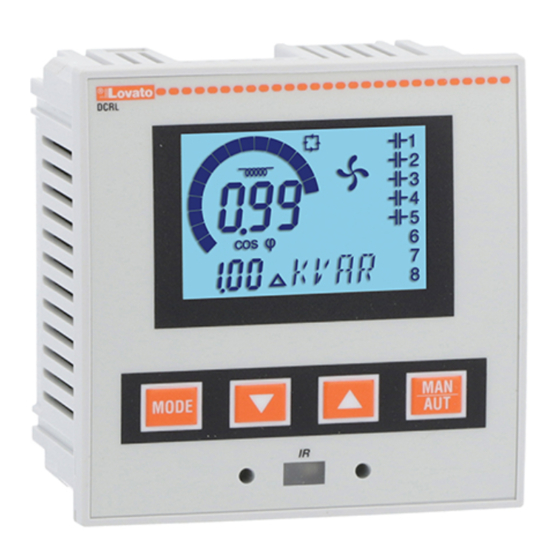
– Flush-mount, standard 96x96mm housing – Backlit LCD screen – Versions: • DCRL3 with 3 relays, expandable to 6 max. • DCRL5 with 5 relays, expandable to 8 max. – 4 navigation keys for function and settings – Alarm messages in 6 languages –... -
Page 3: Display Indications
OPERATING MODES There are three possible operating modes, listed below: TEST Mode – When the unit is brand new and has never been programmed, it automatically enters in TEST mode that allows the installer to manually activate the individual relay outputs, so you can verify the correct wiring of the panel –... -
Page 4: Description
MEASURES – The DCRL provides a set of measurements displayed on the alphanumeric display, in conjunction with the current cosphi that is always displayed on the main display – Press the MODE key to scroll through the measures in rotation –... -
Page 5: Keypad Lock
KEYPAD LOCK – A function to exclude all modification to operating parameters can be enabled; measurement viewing is still provided in any case – To lock and unlock the keypad, press and keep MODE key pressed. Then press the L key three times and the M key twice and after that release MODE –... -
Page 6: Rapid Ct Setup
PARAMETER SETTING WITH PC – You can use the DCRG Remote control software to transfer (previously programmed) setup parameters from the DCRL to the hard drive of the PC and vice versa – The parameter may be partially transferred from the PC to the DCRL, transferring only the parameters of the specified menus. PARAMETER SETTING (SETUP) FROM FRONT PANEL To access the programming menu (setup): –... -
Page 7: Parameter Table
PARAMETER TABLE – Below are listed all the programming parameters in tabular form. For each parameter are indicated the possible setting range and factory default, as well as a brief explanation of the function of the parameter. The description of the parameter shown on the display can in some cases be different from what is reported in the table because of the reduced number of characters available. The parameter code can be used however as a reference –... - Page 8 P.11 ... P.18 – Function of output relays 1 ... 8: OFF = Not used. 1 .. 32 = Weight of the step. This relay drives a bank of cpacitors which power is n times (n = 1…32) the smallest power defined with parameter P.06. ON = Always on.
- Page 9 P.21 – If set to OFF, password management is disabled and anyone has access to the settings and commands menu. P.22 – With P.21 enabled, this is the value to specify for activating user level access. See Password access chapter. P.23 –...
-
Page 10: Alarm Description
ALARMS – When an alarm is generated , the display will show an alarm icon, the code and the description of the alarm in the language selected – If the navigation keys in the pages are pressed, the scrolling message showing the alarm indications will disappear momentarily, to reappear again after 30 seconds –... -
Page 11: Wiring Diagrams
– For the electrical connections see the wiring diagrams in the dedicated chapter and the requirements reported in the technical characteristics. WIRING DIAGRAMS WARNING! Disconnect the line and the supply when servicing on terminals. Three-phase stamdard wiring MAINS DCRL DCRL3 L1 L2 L3 1 2 3 4 DCRL5 INPUT INPUT VOLTAGE... - Page 12 Single-phase wiring MAINS DCRL DCRL3 1 2 3 4 DCRL5 INPUT INPUT VOLTAGE SUPPLY CURRENT 100-600V 100-440V S1 S2 14 13 6 7 8 9 10 11 12 2x1A 2x1A FU10 LOAD SINGLE-PHASE CONNECTION Wiring configuration for single-phase applications Voltage measure...
-
Page 13: Mechanical Dimensions And Panel Cutout
TERMINAL POSITION DCRL3 DCRL5 Aux supply Aux supply 100-440V~ 100-440V~ 50/60Hz 50/60Hz 3,5 W 3,5 W 9,5 VA 9,5 VA V Input V Input 100-600V~ 100-600V~ 50/60Hz 50/60Hz MECHANICAL DIMENSIONS AND PANEL CUTOUT [mm] EXP 10... -
Page 14: Technical Carachteristics
Field Wiring Terminals Tightening Torque: 4.5lb.in Power consumption <0.6VA Flat panel mounting on a Type 1 enclosure Relay output: DCRL3 OUT 1 - 2 / DCRL5 OUT 1 - 4 Comply with standards IEC/EN 61010-1, IEC/EN 61010-2-30 Contact type DCRL3... - Page 15 REGOLATORE AUTOMATICO DEL FATTORE DI POTENZA Manuale operativo LOVATO ELECTRIC S.P.A. 24020 GORLE (BERGAMO) ITALIA VIA DON E. MAZZA, 12 TEL. 035 4282111 FAX (Nazionale): 035 4282200 FAX (International): +39 035 4282400 DCRL3 - DCRL5 E-mail info@ ovato lectric.com www. ovato lectric.com WARNING! ATTENZIONE! –...
- Page 16 – Montaggio a pannello, contenitore standard 96x96mm. – Display LCD retroilluminato. – Versioni: • DCRL3 con 3 gradini, espandibile a 6 max. • DCRL5 con 5 gradini, espandibile a 8 max. – 4 tasti di navigazione per funzioni ed impostazioni.
- Page 17 MODI OPERATIVI Esistono tre possibili modi operativi, elencati di seguito: Modo TEST – Quando l’apparecchio é nuovo di fabbrica e non è mai stato programmato, entra automaticamente nel modo TEST che consente all’installatore di attivare manualmente le singole uscite a relè, in modo da poter verificare la correttezza del cablaggio del quadro.
- Page 18 MISURE – La DCRL fornisce una serie di misure visualizzate sul display alfanumerico, in abbinamento al cosfi attuale che rimane sempre visualizzato sul display principale. – Premendo il tasto MODE è possibile scorrere fra le misure a rotazione. – Dopo 30 secondi senza premere tasti, la visualizzazione ritorna automaticamente alla misura di default definita con il parametro P.47. –...
- Page 19 BLOCCO TASTIERA – È possibile attivare una funzione che impedisce la modifica dei parametri di funzionamento, ma che consente di accedere alle misure. – Per bloccare o sbloccare la tastiera, premere e tenere premuto MODE, premere tre volte L, due volte M e quindi rilasciare MODE. –...
- Page 20 IMPOSTAZIONE PARAMETRI DA PC – Mediante il software di setup DCRG Remote control è possibile effettuare il trasferimento dei parametri di setup (precedentemente impostati) da DCRL al disco del PC e viceversa. – Il trasferimento dei parametri da PC a DCRL può essere parziale, cioè solo i parametri dei menu specificati. IMPOSTAZIONE DEI PARAMETRI (SETUP) DAL PANNELLO FRONTALE Per accedere al menu di programmazione (setup): –...
- Page 21 TABELLA DEI PARAMETRI – Di seguito vengono riportati tutti i parametri di programmazione disponibili in forma tabellare. Per ogni parametro sono indicati il range di impostazione possibile ed il default di fabbrica, oltre ad una spiegazione della funzionalità del parametro. La descrizione del parametro visibile sul display può in qualche caso differire da quanto riportato in tabella a causa del ridotto numero di caratteri disponibile. Il codice del parametro vale comunque come riferimento.
- Page 22 P.11 ... P.18 – Funzione dei relè di uscita 1…8: OFF = Non utilizzato 1..32 = Peso dello step. A questo relè è collegato un banco di condenstaori di potenza n volte (n=1…32) quella del più piccolo, definita con P.06. ON = Sempre attivato.
- Page 23 P.21 – Se impostato ad OFF, la gestione delle password è disabilitata e l’accesso alle impostazioni e al menu comandi è libero. P.22 – Con P.21 attivo, valore da specificare per attivare l’accesso a livello utente. Vedere capitolo Accesso tramite password. P.23 –...
- Page 24 ALLARMI – Al sorgere di un allarme, il display mostra una icona di allarme, un codice identificativo e la descrizione dell’allarme nella lingua selezionata. – Se vengono premuti dei tasti di navigazione delle pagine, la scritta scorrevole con le indicazioni di allarme scompare momentaneamente per poi ricomparire dopo 30 secondi. –...
- Page 25 – Per i collegamenti elettrici fare riferimento agli schemi di connessione riportati nell’apposito capitolo e alle prescrizioni riportate nelle caratteristiche tecniche. SCHEMI DI COLLEGAMENTO ATTENZIONE!! Togliere sempre tensione quando si opera sui morsetti. Inserzione trifase standard MAINS DCRL DCRL3 L1 L2 L3 DCRL5 1 2 3 4 INPUT INPUT CURRENT...
- Page 26 Inserzione monofase MAINS DCRL DCRL3 DCRL5 1 2 3 4 INPUT INPUT CURRENT VOLTAGE SUPPLY 100-600V 100-440V S1 S2 14 13 6 7 8 9 10 11 12 2x1A 2x1A FU10 LOAD INSERZIONE MONOFASE Configurazione per applicazioni con rifasamento monofase...
- Page 27 DISPOSIZIONE MORSETTI DCRL3 DCRL5 Aux supply Aux supply 100-440V~ 100-440V~ 50/60Hz 50/60Hz 3,5 W 3,5 W 9,5 VA 9,5 VA V Input V Input 100-600V~ 100-600V~ 50/60Hz 50/60Hz DIMENSIONI MECCANICHE E FORATURA PANNELLO [mm] EXP 10...
- Page 28 Field Wiring Terminals Tightening Torque: 4.5lb.in Autoconsumo <0,6VA Flat panel mounting on a Type 1 enclosure Uscite a relè: DCRL3 OUT 1 - 2 / DCRL5 OUT 1 - 4 Conformi alle norme IEC/EN 61010-1, IEC/EN 61010-2-30 Tipo di contatto...
Need help?
Do you have a question about the DCRL3 and is the answer not in the manual?
Questions and answers