Table of Contents
Advertisement
ACHTUNG!
● Dieses Handbuch vor Gebrauch und Installation aufmerksam lesen.
● Zur Vermeidung von Personen- und Sachschäden dürfen diese Geräte
nur von qualifiziertem Fachpersonal und unter Befolgung der einschlägigen
Vorschriften installiert werden.
● Vor jedem Eingriff am Instrument die Spannungszufuhr zu den Messeingängen trennen und
die Stromwandler kurzschließen
● Bei zweckwidrigem Gebrauch der Vorrichtung übernimmt der Hersteller keine Haftung für die
elektrische Sicherheit.
● Die in dieser Broschüre beschriebenen Produkte können jederzeit weiterentwickelt und
geändert werden. Die im Katalog enthaltenen Beschreibungen und Daten sind daher
unverbindlich und ohne Gewähr.
● In die elektrische Anlage des Gebäudes ist ein Ausschalter oder Trennschalter einzubauen.
Dieser muss sich in unmittelbarer Nähe des Geräts befinden und vom Bediener leicht zugänglich
sein. Er muss als Trennvorrichtung für das Gerät gekennzeichnet sein: IEC/ EN 61010-1 §
6.11.2.1.
● Das Instrument mit einem weichen Tuch reinigen, keine Scheuermittel, Flüssigreiniger oder
Lösungsmittel verwenden.
Inhalt
Vorwort
Bei Entwicklung des automatischen Leistungsfaktorreglers DCRL wurde
dem Stand der Technik der erforderlichen Funktionen für die
Anwendungen der Leistungsfaktorkorrektur Rechnung getragen. Der
DCRL hat ein eigenes, extrem kompaktes Gehäuse und vereint das
moderne Design der Frontblende mit der praktischen Überwachung und
der Möglichkeit der Erweiterung an der Rückseite, wo ein Modul der Serie
EXP eingesetzt werden kann. Das LCD-Display bietet eine
leichtverständliche und intuitive Benutzeroberfläche.
Doc: I377DEGB03_14.doc
DE
DCRL3 - DCRL5
Automatischer
Leistungsfaktorregler
BETRIEBSANLEITUNG
Seite
1
2
2
2
3
4
5
5
6
6
6
6
7
8
12
12
13
14
15
16
16
18
18
18
19
GB
DCRL3 - DCRL5
Automatic Power Factor
Controller
INSTRUCTIONS MANUAL
WARNING!
x Carefully read the manual before the installation or use.
x This equipment is to be installed by qualified personnel, complying to
current standards, to avoid damages or safety hazards.
● Before any maintenance operation on the device, remove all the voltages from measuring
and supply inputs and short-circuit the CT input terminals.
● Products illustrated herein are subject to alteration and changes without prior notice.
● Technical data and descriptions in the documentation are accurate, to the best of our
knowledge, but no liabilities for errors, omissions or contingencies arising there from are
accepted.
● A circuit breaker must be included in the electrical installation of the building. It must be
installed close by the equipment and within easy reach of the operator.
It must be marked as the disconnecting device of the equipment:
IEC /EN 61010-1 § 6.11.2.1.
● Clean the instrument with a soft dry cloth; do not use abrasives, liquid detergents or
solvents
.
Index
Installation
Introduction
The DCRL automatic power factor control unit has been designed to offer
state-of-the-art functions for power factor compensation applications.
Built with dedicated components and extremely compact, the DCRL
combines the modern design of the front panel with practical installation
and the possibility of expansion from the rear, where one EXP series
module can be slotted. The LCD screen provides a clear and intuitive
user interface.
04/03/2014
Page
1
2
2
2
3
4
5
5
6
6
6
6
7
8
12
12
13
14
15
16
16
18
18
18
19
p. 1 / 19
Advertisement
Table of Contents

Subscribe to Our Youtube Channel
Related Manuals for LOVATO ELECTRIC DCRL Series


Summary of Contents for LOVATO ELECTRIC DCRL Series
-
Page 1: Table Of Contents
DCRL3 – DCRL5 DCRL3 – DCRL5 Automatischer Automatic Power Factor Leistungsfaktorregler Controller BETRIEBSANLEITUNG INSTRUCTIONS MANUAL ACHTUNG! WARNING! x Carefully read the manual before the installation or use. ● Dieses Handbuch vor Gebrauch und Installation aufmerksam lesen. x This equipment is to be installed by qualified personnel, complying to ●... -
Page 2: Beschreibung
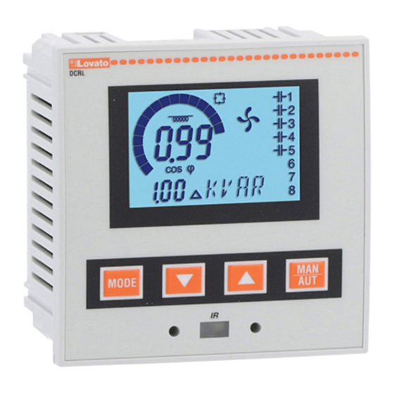
Beschreibung Description x Automatischer Leistungsfaktorregler. x Automatic power factor controller. x Aufbaumontage, Standardgehäuse 96x96mm. x Flush-mount, standard 96x96mm housing. x LCD-Display mit Hintergrundbeleuchtung. x Backlit LCD screen. x Ausführungen: x Versions: DCRL3 mit 3 Stufen, erweiterbar auf max. 5 DCRL3 with 3 relays, expandable to 5 max. DCRL5 mit 5 Stufen, erweiterbar auf max. -
Page 3: Betriebsarten
Betriebsarten Operating modes Es gibt drei mögliche Betriebsarten, die nachstehend aufgeführt werden: There are three possible operating modes, listed below: Betriebsart TEST TEST Mode x Wenn das Gerät fabrikneu ist und noch nie programmiert wurde, schaltet x When the unit is brand new and has never been programmed, it es automatisch auf die Betriebsart TEST, damit der Installationstechniker automatically enters in TEST mode that allows the installer to die einzelnen Relaisausgänge von Hand aktivieren kann, um zu prüfen,... -
Page 4: Messungen
Messungen Measures x Der DCRL stellt mehrere Messungen bereit. Diese werden zusammen x The DCRL provides a set of measurements displayed on the mit dem aktuellen cosfi, der immer auf dem Hauptdisplay angezeigt alphanumeric display, in conjunction with the current cosphi that is wird, auf dem alphanumerischen Display angezeigt. -
Page 5: Tastatursperre
n Diese Messungen werden nur angezeigt, wenn die Funktion Justierung n These measures are shown only if the Step trimming function is enabled Stufenleistung freigeben ist (P.25=ON) und das Passwort der erweiterten Ebene (P.25=ON) and the advanced password is enabled and entered. freigegeben ist und eingegeben wurde. -
Page 6: Programmierschnittstelle Ir
Programmierschnittstelle IR IR programming port x Die Konfiguration der Parameter des DCRL ist über die frontseitige x The parameters of the DCRL can be configured through the front optische Schnittstelle, über den USB-Programmier-Stick IR-USB Code optical port, using the IR-USB code CX01 programming dongle, or with CX01 oder über den Stick IR-WiFi Code CX02 möglich. -
Page 7: Schnelleinstellung Stromwandler
x In der nachstehenden Tabelle sind die verfügbaren Untermenüs The following table lists the available submenus: aufgeführt: Description Access to Base menu Code Beschreibung Zugang zum Basismenü Accesso to Advanced menu Zugang zum erweiterten Menü Accesso to Alarm menu Zugang zum Alarmmenü Access to Command menu Zugang zum Befehlsmenü... -
Page 8: Parametertabelle
Parametertabelle Parameter table x Die nachfolgende Tabelle enthält alle verfügbaren x Below are listed all the programming parameters in tabular form. For each Programmierparameter. Für jeden Parameter sind der mögliche parameter are indicated the possible setting range and factory default, as Wertebereich, die Werkseinstellung und eine Erklärung der well as a brief explanation of the function of the parameter. - Page 9 P.01 – Wert des Primärkreises der Stromwandler. Beispiel: Bei Stromwandler P.01 - The value of the primary current transformer. Example: with CT 800/5 set 800/5 den Wert 800 eingeben. Wenn diese Option auf OFF eingestellt ist, fordert 800. If set to OFF, after the power-up the device will prompt you to set the CT and das Gerät bei Einschalten der Spannungsversorgung zur Einstellung des allow direct access to this parameter.
- Page 10 P.30 Abschaltempfindlichkeit. OFF / 1 – 600 P.30 Disconnection OFF / 1 – 600 sensitivity P.31 Stufen-Ausschaltung mit Deaktiviert P.31 Step disconnection passing OFF Disabled Wechsel in MAN Aktiviert in MAN ON Enabled P.32 Alarm-Schwellenwert OFF / 100...150 P.32 Capacitor current overload OFF / 100...150 Überlaststrom alarm threshold...
- Page 11 P.28 – Auswahl des Stufen-Einschaltmodus. P.28 - Selecting mode of steps insertion. Standard – Normaler Betrieb mit freier Wahl der Stufen Standard mode - Normal operation with free selection of the steps Linear - Die Stufen werden nur nacheinander von links nach rechts unter Linear mode - the steps are connected in progression from left towards Befolgung der Stufennummer eingeschaltet, um dann umgekehrt gemäß...
-
Page 12: Alarme
P.97 Freigabe Alarm A13 P.97 A13 Alarm enable DISC DISC P.98 Verzögerung Alarm A13 0-240 P.98 A13 alarm delay 0-240 P.99 M.E. Verzögerung A13 min. P.99 A13 delay uom P.61 – Aktiviert den Alarm A01 und gibt vor, wie sich das Steuergerät verhalten P.61 - Enable alarm A01 and defines the behavior of the controller when the alarm soll, wenn der Alarm aktiv ist: is active:... -
Page 13: Default Alarmeigenschaften
Spannungseinbruch An den Spannungseingängen ist ein A10 Voltage THD too high The THD of the plant voltage is higher than länger als 8ms dauernder the threshold set with P.43. Spannungseinbruch aufgetreten. A11 Current THD too high The THD of the plant current is higher than Spannungsklirrfaktor Der gemessene Spannungsklirrfaktor the threshold set with P.44. -
Page 14: Befehlsmenü
Befehlsmenü Commands menu x Das Befehlsmenü dient zur Ausführung gelegentlicher Vorgänge, wie das x The commands menu allows executing some occasional operations like reading Rücksetzen von Messungen, Zählern, Alarmen usw. peaks resetting, counters clearing, alarms reset, etc. x Wenn das Passwort für die erweiterte Ebene eingegeben wurde, können x If the Advanced level password has been entered, then the commands menu über das Befehlsmenü... -
Page 15: Verwendung Dongle Cx02
Verwendung Dongle CX02 CX02 Dongle usage x Der Kopierschutzstecker (Dongle) CX02 stellt nicht nur die Funktion der x The CX02 dongle offers WiFi Access point capability for connection to PC, Tablet WLAN-Verbindung mit PC, Tablet oder Smartphone bereit, sondern or smartphones. In addition to this function it also offer the possibility to store and ermöglicht auch die Speicherung und Übertragung eines Datenblocks transfer a block of data from/to the DCRL. -
Page 16: Installation
Installation Installation x Der DCRL ist für die Unterputzmontage bestimmt. Bei korrektem Einbau x DCRL is designed for flush-mount installation. With proper mounting, it wird Schutzart IP54 an der Vorderseite garantiert. guarantees IP54 front protection. x Jeden der vier Clips von der Innenseite der BLK-Anlage in eine der zwei x From inside the panel, for each four of the fixing clips, position the clip in one of seitlichen Führungen stecken und anschließend auf die Kante des Clips the two sliding guide, then press on the clip corner until the second guide snaps... - Page 17 Einphasenanschluss Single-phase wiring EINPHASENANSCHLUSS SINGLE-PHASE CONNECTION Konfiguration für Anwendungen mit Blindleistungskompensation in Einphasensystem Wiring configuration for single-phase applications Spannungsmessung 1 Messung Phasenspannung L1-N Voltage measure 1 phase voltage reading L1-N Strommessung Phase L1 Current measure L1 phase Zwischen V (L1-N ) und I (L1) Ö 0° Between V (L1-N ) and I (L1) Ö...
-
Page 18: Klemmenanordnung
Klemmenanordnung Terminals position DCRL3 DCRL5 Aux supply Aux supply 100-440V~ 100-440V~ 50/60Hz 50/60Hz 3,5 W 3,5 W 9,5 VA 9,5 VA V Input V Input 100-600V~ 100-600V~ 50/60Hz 50/60Hz Mechanische Abmessungen und Bohrung der Platte (mm) Mechanical dimensions and front panel cutout (mm) Technische Merkmale Technical characteristics Stromversorgung... -
Page 19: Chronik Der Revisionen Der Betriebsanleitung
Stromeingänge Current inputs Nennstrom Ie 1A~ oder 5A~ Rated current Ie 1A~ or 5A~ Messbereich Für Skala 5A: 0,025 - 6A~ Measuring range For 5A scale: 0.025 - 6A~ Für Skala 1A: 0,025 – 1,2A~ For 1A scale: 0.025 – 1.2A~ Eingangstyp Über externen Stromwandler Type of input...
Need help?
Do you have a question about the DCRL Series and is the answer not in the manual?
Questions and answers