LOVATO ELECTRIC DCRG8 Installation Manual
Automatic power factor controller
Hide thumbs
Also See for DCRG8:
- User manual (32 pages) ,
- Installation manual (6 pages) ,
- Instruction manual (38 pages)
Table of Contents
Advertisement
Quick Links
LOVATO ELECTRIC S.P.A.
24020 GORLE (BERGAMO) ITALIA
VIA DON E. MAZZA, 12
TEL. 035 4282111
FAX (Nazionale): 035 4282200
FAX (International): +39 035 4282400
L
E
ovato
lectric.com
E-mail info@
L
E
Web
www.
ovato
lectric.com
The complete operating manual is
downloadable from website
www.lovatoelectric.com
Il manuale operativo completo è
scaricabile dal sito www.lovatoelectric.com
WARNING!
– Carefully read the manual before the installation or use.
– This equipment is to be installed by qualified personnel, complying to current standards, to avoid
damages or safety hazards.
– Before any maintenance operation on the device, remove all the voltages from measuring and supply
inputs and short-circuit the CT input terminals.
– The manufacturer cannot be held responsible for electrical safety in case of improper use of the
equipment.
– Products illustrated herein are subject to alteration and changes without prior notice. Technical data
and descriptions in the documentation are accurate, to the best of our knowledge, but no liabilities for
errors, omissions or contingencies arising therefrom are accepted.
– A circuit breaker must be included in the electrical installation of the building. It must be installed
close by the equipment and within easy reach of the operator. It must be marked as the disconnecting
device of the equipment: IEC /EN 61010-1 § 6.11.2.1.
– Clean the instrument with a soft dry cloth; do not use abrasives, liquid detergents or solvents.
INTRODUCTION
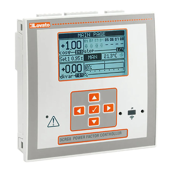
The DCRG8 automatic power factor controler has been designed to offer state-of-the-art functions for
power factor compensation applications. Built with dedicated components and extremely compact, the
DCRG8 combines the modern design of the front panel with practical installation and the possibility of
expansion at the rear, where EXP series modules can be slotted. The LCD screen provides a clear and
intuitive user interface.
GB
I
DCRG8
F
Available in French at www.LovatoElectric.com/I340IGBFE.pdf
D
Available in German at www.LovatoElectric.com/I340D.pdf
PL
Available in Polish at www.LovatoElectric.com/I340PL.pdf
AUTOMATIC POWER FACTOR CONTROLLER
Installation manual
REGOLATORE AUTOMATICO DEL FATTORE DI POTENZA
Manuale d'installazione
RU
ATTENZIONE!!
– Leggere attentamente il manuale prima dell'utilizzo e l'installazione.
– Questi apparecchi devono essere installati da personale qualificato, nel rispetto delle vigenti normative
impiantistiche, allo scopo di evitare danni a persone o cose.
– Prima di qualsiasi intervento sullo strumento, togliere tensione dagli ingressi di misura e di
alimentazione e cortocircuitare i trasformatori di corrente.
– Il costruttore non si assume responsabilità in merito alla sicurezza elettrica in caso di utilizzo
improprio del dispositivo.
– I prodotti descritti in questo documento sono suscettibili in qualsiasi momento di evoluzioni o di
modifiche. Le descrizioni ed i dati a catalogo non possono pertanto avere alcun valore contrattuale.
– Un interruttore o disgiuntore va compreso nell'impianto elettrico dell'edificio. Esso deve trovarsi in
stretta vicinanza dell'apparecchio ed essere facilmente raggiungibile da parte dell'operatore. Deve
essere marchiato come il dispositivo di interruzione dell'apparecchio: IEC/ EN 61010-1 § 6.11.2.1.
– Pulire lo strumento con panno morbido, non usare prodotti abrasivi, detergenti liquidi o solventi.
INTRODUZIONE
Il regolatore automatico del fattore di potenza DCRG8 è stato progettato incorporando lo stato dell'arte
delle funzioni richieste per le applicazioni di rifasamento. Realizzato con un contenitore dedicato, di
dimensioni estremamente compatte, il DCRG8 unisce il moderno design del frontale alla praticità di
montaggio e alla possibilità di espansione sul retro, dove è possibile alloggiare moduli della serie EXP.
Il display grafico LCD consente una interfaccia utente chiara ed intuitiva.
E
Available in Spanish at www.LovatoElectric.com/I340IGBFE.pdf
CZ
Available in Czech at www.LovatoElectric.com/I340CZ.pdf
Available in Russian at www.LovatoElectric.com/I340RU.pdf
1
Advertisement
Table of Contents

Related Manuals for LOVATO ELECTRIC DCRG8


Summary of Contents for LOVATO ELECTRIC DCRG8
- Page 1 Realizzato con un contenitore dedicato, di DCRG8 combines the modern design of the front panel with practical installation and the possibility of dimensioni estremamente compatte, il DCRG8 unisce il moderno design del frontale alla praticità di expansion at the rear, where EXP series modules can be slotted.
- Page 2 DESCRIPTION DESCRIZIONE – Automatic power factor controller with 8 built-in relays for capacitor steps, expandable to 16 relays. – Controllore automatico del fattore di potenza a 8 gradini per controllo condensatori, espandibile a 16 gradini. – 128x80 pixel, backlit LCD screen with 4 grey levels. –...
-
Page 3: Menu Principale
MAN Mode Modo MAN – When the unit is in manual mode, you can select one of the steps and manually connect or – Quando l’apparecchio é in modalità manuale, é possibile selezionare uno degli step ed inserirlo o disconnect it. disinserirlo manualmente. - Page 4 – Thanks to expansion bus, the DCRG8 can be expanded with EXP… series modules. – Grazie al suo bus di espansione, la DCRG8 può essere espansa con dei moduli aggiuntivi EXP…. – It is possible to connect a maximum of 4 EXP… modules at the same time.
-
Page 5: Ir Programming Port
– This programming port has the following advantages: CX02. • You can configure and service the DCRG8 without access to the rear of the device or having to – Questa porta di programmazione ha i seguenti vantaggi: open the electrical board. - Page 6 PARAMETER SETTING (SETUP) FROM FRONT PANEL IMPOSTAZIONE DEI PARAMETRI (SETUP) DAL PANNELLO FRONTALE – To open the parameters programming menu (setup): – Per accedere al menu di programmazione dei parametri (setup): • turn the unit in MAN mode and disconnect all the steps •...
-
Page 7: Parameter Table
– Rammentiamo che, per i soli dati di setup modificabili da tastiera, è possibile fare una copia di saved in the eeprom memory of the DCRG8. This data can be restored when necessary in the work sicurezza (backup) nella memoria eeprom della DCRG8. Questi stessi dati all’occorrenza possono memory. - Page 8 M02 – GENERAL Default Range M02 - GENERALE Default Range P02.01 CT primary OFF/1-30000 P02.01 Primario TA OFF/1-30000 P02.02 CT secondary P02.02 Secondario TA P02.03 Plant type Three-ph Three-phase P02.03 Tipologia impianto Trifase Trifase Single phase Monofase P02.04 Current reading phase P02.04 Fase lettura correnti L1 L2 L3...
- Page 9 Nota: Questo menu è diviso in 16 sezioni, riferite alle 16 possibili uscite digitali OUT1…OUT16 which can be managed by the master DCRG8; OUT81..OUT08 on the base board and OUT09…OUT16 gestibili dalla DCRG8 master, di cui OUT01..OUT08 sulla scheda base e OUT09…OUT16 sugli on any installed expansion modules.
- Page 10 – Se l’allarme non si resetta, significa che persiste la causa che lo ha provocato. – In the case of one or more alarms, the behaviour of the DCRG8 depends on the properties settings of – In seguito al verificarsi di uno o più allarmi, la DCRG8 ha un comportamento dipendente dalla the active alarms.
-
Page 11: Installation
INSTALLATION INSTALLAZIONE – DCRG8 is designed for flush-mount installation. With proper mounting, it guarantees IP54 front – DCRG8 è destinato al montaggio da incasso. Con il corretto montaggio garantisce una protezione protection. frontale IP54. – Insert the device into the panel hole, making sure that the gasket is properly positioned between the –... -
Page 12: Single-Phase Connection
TYPICAL WIRING DIAGRAMS EXAMPLE (only for reference) ESEMPI DI SCHEMI DI COLLEGAMENTO TIPICI ( solo per riferimento) Standard Three-phase wiring Inserzione trifase standard MAINS DCRG8 L1 L2 L3 2 3 4 INPUT CURRENT VOLTAGE SUPPLY 110-415V~ 1/5A~ 110-600V~ 110-250V= 2 3 4... - Page 13 Full three-phase wiring, without neutral Inserzione trifase completa, senza neutro MAINS DCRG8 L1 L2 L3 N INPUT CURRENT VOLTAGE SUPPLY 100-415V~ 1/5A~ 100-600V~ 110-250V= 9 10 11 12 13 14 15 16 17 18 20 21 22 I1 I2 I3 C...
-
Page 14: Terminals Position
TERMINALS POSITION DISPOSIZIONE MORSETTI I3 C CURRENT INPUT VOLTAGE INPUT AUX SUPPLY Ie = 1/5A~ 100-600V~ 100-415V~ 110-250V= 600V~ 50 / 60 Hz MECHANICAL DIMENSIONS AND FRONT PANEL CUTOUT (mm) DIMENSIONI MECCANICHE E FORATURA PANNELLO (mm) 43.3... -
Page 15: Technical Characteristics
TECHNICAL CHARACTERISTICS Supply Real time clock Rated voltage Us ‚ 100 - 415V Energy storage Back-up capacitors 110 - 250V Operating time without supply voltage About 12...15 days Operating voltage range 90 - 456V Insulation voltage 93.5 - 300V Rated insulation voltage Ui 600V Frequency 45 - 66Hz... -
Page 16: Caratteristiche Tecniche
CARATTERISTICHE TECNICHE Alimentazione Orologio datario Tensione nominale Us ‚ 100 - 415V Riserva di carica Condensatore di back-up 110 - 250V Funzionamento senza tensione di alimentazione Circa 12…15 giorni Limiti di funzionamento 90 - 456V Tensione di isolamento 93,5 - 300V Tensione nominale d’isolamento Ui 600V Frequenza...
Need help?
Do you have a question about the DCRG8 and is the answer not in the manual?
Questions and answers