LOVATO ELECTRIC DCRL8 Instruction Manual
Automatic power factor controller
Hide thumbs
Also See for DCRL8:
- Instruction manual (30 pages) ,
- Installation manual (8 pages) ,
- Instruction manual (19 pages)
Table of Contents
Advertisement
Quick Links
ACHTUNG!
Dieses Handbuch vor Gebrauch und Installation aufmerksam lesen.
Zur Vermeidung von Personen- und Sachschäden dürfen diese Geräte
nur von qualifiziertem Fach, personal und unter Befolgung der
einschlägigen Vorschriften installiert werden.
● Vor jedem Eingriff am Instrument die Spannungszufuhr zu den Messeingängen trennen und
die Stromwandler kurzschließen
● Bei zweckwidrigem Gebrauch der Vorrichtung übernimmt der Hersteller keine Haftung für die
elektrische Sicherheit.
● Die in dieser Broschüre beschriebenen Produkte können jederzeit weiterentwickelt und
geändert werden. Die im Katalog enthaltenen Beschreibungen und Daten sind daher
unverbindlich und ohne Gewähr.
● In die elektrische Anlage des Gebäudes ist ein Ausschalter oder Trennschalter einzubauen.
Dieser muss sich in unmittelbarer Nähe des Geräts befinden und vom Bediener leicht zugänglich
sein. Er muss als Trennvorrichtung für das Gerät gekennzeichnet sein:
IEC/ EN 61010-1 § 6.11.2.1.
● Das Instrument mit einem weichen Tuch reinigen, keine Scheuermittel, Flüssigreiniger oder
Lösungsmittel verwenden.
Inhalt
Vorwort
Bei Entwicklung des automatischen Blindleistungsreglers DCRL8 wurde
dem Stand der Technik -erforderlichen Funktionen für die Anwendungen
der Leistungsfaktorkorrektur- Rechnung getragen. Der DCRL8 hat ein eige-
nes, extrem kompaktes Gehäuse und vereint das moderne Design der
Frontblende mit einer praktischen Montage und der Möglichkeit der Erwei-
terung an der Rückseite, auf dem zwei Module der Serie EXP... eingesetzt
werden können. Das LCD-Display bietet eine leicht verständliche und
intuitive Benutzeroberfläche.
Beschreibung
Automatischer Blindleistungsregler.
Aufbaumontage, Standardgehäuse 144x144 mm.
LCD-Symbol-Display mit Hintergrundbeleuchtung.
Ausführungen:
DCRL8 mit 8 Stufen, erweiterbar auf max. 14
o
5 Navigationstasten für Funktionen und Einstellungen.
Alarmmeldungen mit 6-sprachigen Texten (Italienisch, Englisch,
Französisch, Spanisch, Portugiesisch, Deutsch).
Erweiterungsbus mit 2 Steckplätzen für Erweiterungsmodule der Serie
EXP:
o Kommunikationsschnittstellen RS232, RS485, USB, Ethernet.
Doc: I417DGB12_14 correction.doc18/12/2014
19
D
DCRL8
Automatischer Blindleistungsregler
BETRIEBSANLEITUNG
Seite
1
1
2
2
2
3
4
5
5
6
6
7
8
12
12
13
13
14
14
16
17
18
18
19
GB
DCRL8
Automatic Power Factor Controller
INSTRUCTIONS MANUAL
WARNING!
Carefully read the manual before the installation or use.
This equipment is to be installed by qualified personnel, complying to
current standards, to avoid damages or safety hazards.
● Before any maintenance operation on the device, remove all the voltages from measuring
and supply inputs and short-circuit the CT input terminals.
● Products illustrated herein are subject to alteration and changes without prior notice.
● Technical data and descriptions in the documentation are accurate, to the best of our
knowledge, but no liabilities for errors, omissions or contingencies arising there from are
accepted.
● A circuit breaker must be included in the electrical installation of the building. It must be
installed close by the equipment and within easy reach of the operator.
It must be marked as the disconnecting device of the equipment:
IEC /EN 61010-1 § 6.11.2.1.
● Clean the instrument with a soft dry cloth; do not use abrasives, liquid detergents or
solvents
.
Index
Installation
Introduction
The DCRL8 automatic power factor control unit has been designed to
offer state-of-the-art functions for power factor compensation applications.
Built with dedicated components and extremely compact, the DCRL8
combines the modern design of the front panel with practical installation
and the possibility of expansion from the rear, where two EXP series
modules can be slotted. The LCD screen provides a clear and intuitive
user interface.
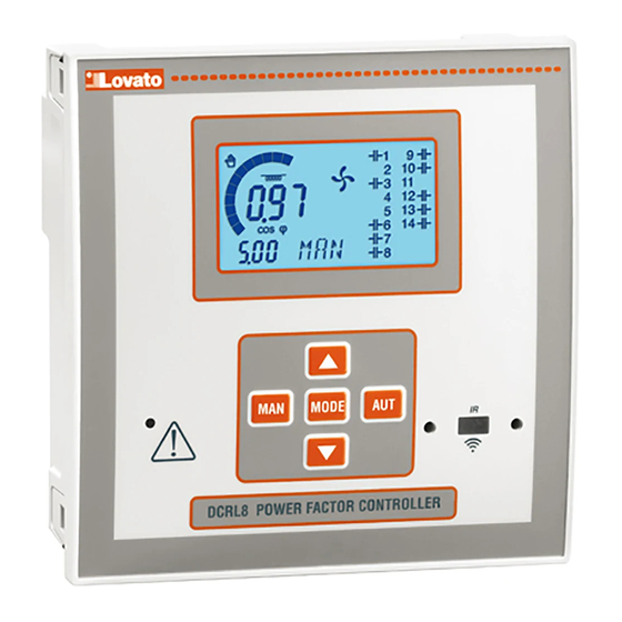
Description
Automatic power factor controller.
Flush-mount, standard 144x144mm housing.
Backlit LCD icon screen.
Versions:
DCRL8 with 8 relays, expandable to 14 max.
o
5 navigation keys for function and settings.
Alarm messages in 6 languages (English, Italian, French, Spanish,
Portuguese, German).
Expansion bus with 2 slot for EXP series expansion modules:
o RS232, RS485, USB, Ethernet communications interface.
o Additional relay outputs.
Page
1
1
2
2
2
3
4
5
5
6
6
7
8
12
12
13
13
14
14
16
17
18
18
19
p. 1 /
Advertisement
Table of Contents

Subscribe to Our Youtube Channel
Related Manuals for LOVATO ELECTRIC DCRL8


Summary of Contents for LOVATO ELECTRIC DCRL8
-
Page 1: Table Of Contents
Vorwort Introduction Bei Entwicklung des automatischen Blindleistungsreglers DCRL8 wurde The DCRL8 automatic power factor control unit has been designed to dem Stand der Technik -erforderlichen Funktionen für die Anwendungen offer state-of-the-art functions for power factor compensation applications. der Leistungsfaktorkorrektur- Rechnung getragen. Der DCRL8 hat ein eige- Built with dedicated components and extremely compact, the DCRL8 nes, extrem kompaktes Gehäuse und vereint das moderne Design der... -
Page 2: Funktion Der Vorderen Tasten
High accuracy TRMS measurements. o Zusätzliche Relaisausgänge. Hohe Genauigkeit dank Echteffektivwertmessung (TRMS). Wide selection of electrical measures, including voltage and current Große Auswahl verfügbarer Messungen, einschließlich Spannungs- und THD with harmonic analysis up to 15 order. ... -
Page 3: Messungen
Measures Der DCRL8 stellt mehrere Messungen bereit. Diese werden zusammen The DCRL8 provides a set of measurements displayed on the mit dem aktuellen cos, der immer auf dem Hauptdisplay angezeigt alphanumeric display, in conjunction with the current cosphi that is wird, auf dem alphanumerischen Display angezeigt. -
Page 4: Tastatursperre
In der nachstehenden Tabelle werden die angezeigten Messungen aufgeführt. Messung Symbol Beschreibung Measure Icon Description kVAr, die notwendig sind, um den Sollwert zu Kvars needed to reach the cosphi setpoint. If Delta-kvar erreichen. Bei positivem Wert Delta-kVAr Delta-kvar delta-kvar is positive cpacitors need to be Δkvar ... -
Page 5: Erweiterbarkeit
Erweiterbarkeit Expandability Dank Erweiterungsbus lässt sich der DCRL8 mit Zusatzmodulen der Thanks to expansion bus, the DCRL8 can be expanded with two Serie EXP... erweitern. EXP… series modules. Die vom DCRL8 unterstützten Module EXP... lassen sich in folgende ... -
Page 6: Parametereinstellung Von Pc, Tablet Oder Smartphone
Tablet/Smartphone: Mit der für die Betriebssysteme Android und iOS Tablet/Smartphone: Using the dedicated application Lovato Electric verfügbaren App Lovato Electric Sam1 und den Dongles WLAN CX02 ist Sam1, available for Android and iOS operative systems together with die einfache und innovative Programmierung der Parameter möglich. -
Page 7: Schnelleinstellung Stromwandler
Es wird daran erinnert, dass nur für die über Tastatur änderbaren DCRL8. This data can be restored when necessary in the work Parameter im EEprom-Speicher des DCRL8 eine Sicherheitskopie memory. -
Page 8: Parametertabelle
Parametertabelle Parameter table Die nachfolgende Tabelle enthält alle verfügbaren Below are listed all the programming parameters in tabular form. For Programmierparameter. Für jeden Parameter sind der mögliche each parameter are indicated the possible setting range and factory Wertebereich, die Werkseinstellung und eine Erklärung der default, as well as a brief explanation of the function of the parameter. - Page 9 P.06 – Wert in kVAr der kleinsten installierten Stufe (Gewichtung 1). Bemessungsleistung der Kondensatorbank, die bei der in P07 angegebenen Bemessungsspannung geliefert wird, und sich in Dreiphasenanwendung auf alle drei P.06 – Value in kvar of the smallest step installed (equivalent to the step weight 1). Kondensatoren bezieht.
- Page 10 P.40 Alarmschwelle Stufe OFF / 25…100 P.40 Step failure alarm OFF / 25…100 defekt threshold P.41 Alarmschwelle max. OFF / 90…150 P.41 Maximum voltage alarm OFF / 90…150 Spannung threshold P.42 Alarmschwelle min. OFF / 60..110 P.42 Minimum voltage alarm OFF / 60..110 Spannung threshold...
- Page 11 P.31 – Wenn dieser Parameter auf ON eingestellt ist, werden die Stufen beim P.31 - If set to ON, when switching from AUT mode to MAN mode, steps are Wechsel von Betriebsart AUT auf Betriebsart MAN nacheinander ausgeschaltet. disconnected in sequence. P.32 –...
-
Page 12: Alarme
Alarm ausgelöst haben, nicht mehr gegeben sind. In the case of one or more alarms, the behaviour of the DCRL8 Nach Auftreten eines oder mehrerer Alarme hängt das Verhalten des depends on the properties settings of the active alarms. -
Page 13: Standard Alarmeigenschaften
Die Taste ▲ drücken und drei Sekunden lang gedrückt halten, wenn der command. DCRL8 shows OK? with a countdown. Befehl ausgeführt werden soll. DCRL8 zeigt OK? mit Countdown. If you press and hold ▲ until the end of the countdown the command ... -
Page 14: Verwendung Dongle Cx02
Press 3 times consecutively and fast the dongle button. Warten, bis die LED LINK orange wird und blinkt. At this point the display of the DCRL8 shows the first of the 6 possible 3 Mal schnell nacheinander die Taste des CX02 drücken. - Page 15 Die Befestigungsschraube mit max. Anzugsmoment 0,5Nm anziehen. In case it is necessary to dismount the system, repeat the steps in Wenn das Gerät ausgebaut werden muss, die vier Schrauben lockern opposite order. und in umgekehrter Reihenfolge vorgehen. ...
-
Page 16: Anschlusspläne
Anschlusspläne Wiring diagrams ACHTUNG!! WARNING! Für Eingriffe an den Klemmen immer Spannungszufuhr trennen. Disconnect the line and the supply when operating on terminals Dreiphasenanschluss Standard Standard Three-phase wiring DREIPHASENANSCHLUSS STANDARD (Default) THREE-PHASE STANDARD CONNECTION (default) Default-Konfiguration für Standardanwendungen Default wiring configuration for standard applications. Spannungsmessung 1 Messung verkettete Spannung L1-L2 Voltage measure... -
Page 17: Klemmenanordnung
HINWEISE NOTES WICHTIG! IMPORTANT! Die Polung des Stromeingangs ist unerheblich. The polarity of the current/voltage input is irrilevant. Anschluss an MS MV wiring Anschluss mit Messungen und Blindleistungskompensation an MS Configuration with MV measurement and correction Spannungsmessung 3 Messungen verkettete Spannung L1-L2, L2- Voltage measure 3 ph-to-ph voltage reading L1-L2, L2-L3, L3-L1 L3, L3-L1 an Mittelspannung... -
Page 18: Mechanische Abmessungen Und Bohrung Der Platte
Mechanische Abmessungen und Bohrung der Platte (mm) Mechanical dimensions and panel cutout (mm) Technische Merkmale Technical characteristics Stromversorgung Supply Nennspannung Us 100 - 440V~ Rated voltage Us 100 - 440V~ 110 - 250V= 110 - 250V= Betriebsgrenzen 90 - 484V~ Operating voltage range 90 - 484V~ 93,5 - 300V=... -
Page 19: Chronik Der Revisionen Der Betriebsanleitung
Nenn-Stehstoßspannung Uimp 9,5kV Rated impulse withstand voltage Uimp 9.5kV Haltespannung bei Betriebsfrequenz 5,2kV Power frequency withstand voltage 5,2kV Einsatzbedingungen Ambient operating conditions Betriebstemperatur -20 - +60°C Operating temperature -20 - +60°C Lagertemperatur -30 - +80°C Storage temperature -30 - +80°C Relative Feuchte Relative humidity 80% (IEC/EN 60068-2-78)
Need help?
Do you have a question about the DCRL8 and is the answer not in the manual?
Questions and answers