
Related Manuals for Ingersoll-Rand EU


Summary of Contents for Ingersoll-Rand EU
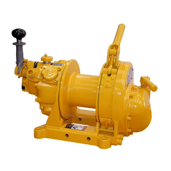
- Page 1 Product Information EU AND EUL AIR WINCHES (Dwg. MHP1234) Save These Instructions Form MHD56383 Edition 1 November 2010 43809441 2010 Ingersoll-Rand Company ©...
-
Page 2: Product Description
MHD56384 PRODUCT DESCRIPTION The EU and EUL winches are powered by a radial piston air motor. The output from the motor is transferred to the drum by the motor shaft. The motor shaft rotates a series of connected spur gears which form a reduction assembly. Output from the reduction assembly drives the wire rope drum. -
Page 3: Specifications
SPECIFICATIONS Model Code Explanation Example: EUAB/PT - P AB/PT Model: 2,000 lbs (908 kg) Winch with standard drum length 2,000 lbs (908 kg) Winch with long drum length Options: Automatic drum band brake Remote full flow control RCAB Remote full flow control and automatic band brake PTAB Remote full flow pendant and automatic band brake AB/PT... -
Page 4: Installation
Safety Information Manual. Installing Wire Rope EU Model – Bolt Hole Dimensions Refer to Dwg. MHP1334 on page 9, A. Wire Rope; B. Setscrew. 1. Cut wire rope to length and fuse end to prevent fraying of strands in accordance Refer to Dwg. -
Page 5: Air Supply
3. Apply the wire rope so that it winds over the top when the drum is rotated in a NOTICE direction that is counterclockwise when facing the motor end of the winch. This is indicated by instruction plate on the gear case. 4. -
Page 6: Operation
OPERATION It is recommended that the user and owner check all appropriate and applicable * For distances greater than 66 feet (20 metres) contact Technical Sales for control regulations before placing this product into use. Refer to Product Safety Information acceptability. -
Page 7: General Lubrication
3. Muffler. Visually check for restrictions or external damage. Clear restrictions or 13. Lubrication. Refer to “LUBRICATION” on page 7 for recommended procedures replace if damaged. and lubricants. 4. Manual Shut-Off Valve. Test shut-off valve to ensure proper operation and free 14. - Page 8 The motor should be level-checked daily or at the start of each shift after any accumulated water has been drained off. When motors are operated in temperatures below freezing, wait long enough at the end of shift for water to separate from oil but not long enough for it to freeze.
- Page 9 PRODUCT INFORMATION GRAPHICS EU Model - Bolt Hole Dimensions Base Air Out Center Regulator Line D=13/16 in. 45-1/4° (20 mm) x 4 holes Air In R=5-5/8 in. (143 mm) 1-1/4 in. (32 mm) 7 Tap 1-3/8 in. (35 mm) deep Lubricator R=6-1/2 in.
- Page 10 PRODUCT INFORMATION GRAPHICS (CONTINUED) (Dwg. MHP2233) Haul-In Neutral Payout (Dwg. MHP3138) Form MHD56383 Edition 1...
-
Page 11: Warranty
WARRANTY Ingersoll Rand Limited Warranty IR's maximum liability is limited to the purchase price of the Product and in no event Ingersoll Rand Company (“IR”) warrants to the original user its material handling shall IR be liable for any consequential, indirect incidental or special damages of any products (“Products”) to be free of defects in material and workmanship for a period nature arising from the sale or use of the Product, whether in contract, tort or of one year from the date of purchase. - Page 12 www.ingersollrandproducts.com...
Need help?
Do you have a question about the EU and is the answer not in the manual?
Questions and answers