Table of Contents
Advertisement
Quick Links
UM1700
User manual
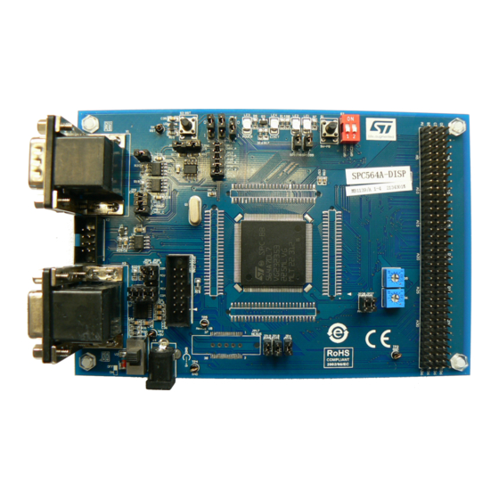
SPC56A-Discovery+ Evaluation board
Introduction
The SPC56A-Discovery+ Evaluation board, here after named SPC56A-DISP, helps you evaluate the SPC56 A line Power
®
Architecture
Microcontrollers.
The discovery board is based on SPC564A70L7, a 32-bit Power Architecture Book E compliant e200z335 CPU core with 1.5
Mbyte on-chip in an LQFP176 package.
The numerous interfaces including CAN/SCI/K-LINE/DSPI/GPIO make the SPC564A-DISP an excellent starter kit for customer
quick evaluation and project development.
The SPC56 A line is designed to address cost sensitive powertrain and transmission applications.
The SPC56 A line key functionality is a Time Processing Unit (eTPU) with a coprocessor to create events in sync with internal or
external signals without flooding the CPU with interrupt to serve.
Free ready-to-run application firmware examples are available inside SPC5Studio at
www.st.com
to support quick evaluation
and development.
UM1700 - Rev 3 - July 2021
www.st.com
For further information contact your local STMicroelectronics sales office.
Advertisement
Table of Contents

Related Manuals for ST SPC56A Series


Summary of Contents for ST SPC56A Series
- Page 1 The SPC56 A line key functionality is a Time Processing Unit (eTPU) with a coprocessor to create events in sync with internal or external signals without flooding the CPU with interrupt to serve. Free ready-to-run application firmware examples are available inside SPC5Studio at www.st.com to support quick evaluation and development.
-
Page 2: Spc564A-Disp With Spc564A70L7
UM1700 SPC564A-DISP with SPC564A70L7 SPC564A-DISP with SPC564A70L7 SPC564A-DISP Discovery board Figure 1. SPC564A-DISP Discovery board The content of hardware of SPC564A-DISP withSPC564A70L7 consists of: • SPC564A-DISP Discovery board (see Figure • Power Supply (Mains: 90-240 V - Output: 5 V The PCB, the components and all HW parts assembled in the board meet requirements of the applicable RoHS directives. -
Page 3: Hardware Overview
UM1700 Hardware overview Hardware overview Figure 2. HW overview Start-up LEDs and User Potentiometer Reset configuration button for ADC 2 CAN K-LINE 1 extra CAN 2 SCI SPC56EL70L5 Nexus connector power supply JTAG connector 4x36 Header (Option) and switch power supply The 5 V voltage is used to supply the whole board including SPC564A70L7 and communication interface transceiver chips. -
Page 4: Device Start-Up Configuration
UM1700 Device start-up configuration Device start-up configuration When the MCU is power-on, it will latch the status of pin WKPCFG, BOOTCFG1 and PLLREF. • “WKPCFG” determines the weak pull up/down configuration of eMIOS and eTPUpins; • “BOOTCFG1” is for boot selection; •... -
Page 5: Figure 6. User Leds - Le1/Le2 (Schematic Diagram)
UM1700 User LEDs Figure 6. User LEDs - LE1/LE2 (schematic diagram) Figure 7. User LEDs - LE3/LE4 (schematic diagram) UM1700 - Rev 3 page 5/19... -
Page 6: Jtag/Nexus Debug Connection
UM1700 JTAG/Nexus debug connection JTAG/Nexus debug connection Two kinds of debug interfaces are used in the evaluation board: • the standard 14-pin JTAG connector of PPC for low-cost/end tools; • 3MTM Mictor 38-pin connector for Nexus interface in high-end development tools. Prior to connect any development tool to the debug interface, it is highly recommended to switch off the power supply of the board and make sure the pin 1 of the tools’... -
Page 7: High Speed Can Interface
UM1700 High speed CAN interface High speed CAN interface The whole CAN interface circuit usually includes the CAN module in microcontroller, CAN transceiver and CAN connector. In the evaluation board, CAN module is integrated with L9616 transceiver which supports high-speed CAN. Regarding the CAN connectors, the two basic CAN channels of SPC564A70L7, CANA and CANC, are located in two DB9 male connectors. -
Page 8: Esci/K-Line
UM1700 eSCI/K-LINE eSCI/K-LINE eSCI stands for enhanced serial communication interface, as it enhances the conventional asynchronous RX/TX with DMA and LIN support. High speed CAN interface, HW configurations show the hardware connection on the evaluation board: ST232 is the bridge between RS232 DB9 female interface and TX/RX signal of microcontroller. L9637 is the ISO9141 interface chip. -
Page 9: I/O Header
UM1700 I/O header I/O header All GPIOs/DSPI/eMIOS/eTPU of the MCU can be accessed through the 4x36 I/O headers. Table 3. I/O header: pin out table Pin number AN10/ AN39/ANY AN9/ANX AN37 AN36 AN11/ANZ AN16 AN22 AN24 AN18 PCS_B1/GPIO106 AN27 AN30 PCS_B5/PCS_C0 eTPU_A12/PCS_B1 AN32... - Page 10 UM1700 I/O header Pin number eTPU_A19 eTPU_A27/IRQ15 eTPU_A26/IRQ14 eMIOS13 AN12 SOUT_C_LVDS+ SOUT_C_LVDS- GPIO192 MA0/SDS SOUTB/ GPIO141 GPIO140 eTPU_A29 eTPU_A21 eTPU_A14/PCS_B4 PCS_C2 AN13 GPIO98 eTPU_A9 GPIO143 MA1/SDO GPIO128 RXD_B TXD_B eMIOS11 eTPU_A15/PCS_B5 GPIO92 GPIO91 GPIO190 GPIO129 eMIOS4 eMIOS12/DSPI_C_SOUT eMIOS15 eTPU_A8/eTPU_A20 eTPU_A4 eTPU_A27 IRQ1 SOUT_B_LVDS+...
-
Page 11: Jumper Setting
UM1700 Jumper setting Jumper setting Figure 14. Jumper setting JP11 JP13 JP14 - JP15 - JP16 JP29 GPIO207 JP10 JP30 JP5 - JP3 JP12 JP7 - JP6 GPIO219 JP31 JP26 - JP20 JP28 - JP27 JP19 - JP18 - JP4 JP24 - JP25 - JP23 Table 4. -
Page 12: Table 7. Jumper Setting: Jp14, Jp15, Jp16
UM1700 Jumper setting Table 7. Jumper setting: JP14, JP15, JP16 JP14 JP15 JP16 (10 kΩ to GND) (10 kΩ to GND) (10 kΩ to GND) WKPCFG BOOTCFG1 PLLREF (10 kΩ to Vcc) (10 kΩ to Vcc) (10 kΩ to Vcc) Table 8. -
Page 13: Pcb Layout
UM1700 PCB layout PCB layout Figure 15. PCB layout (top view) GAPG1122130324RI UM1700 - Rev 3 page 13/19... -
Page 14: General Handling Precautions
UM1700 General handling precautions General handling precautions The following precautions are recommended when using the SPC564A-DISP, discovery board: • Do not modify or manipulate the board when the external PSU supply is powered and connected to the board. • Do not open and modify the PSU. Use AC plug adaptor if the main socket is not compatible with the PSU plug. -
Page 15: Revision History
UM1700 Revision history Table 13. Document revision history Date Version Changes 02-Dec-2013 Initial release. Changed value of DC source from 12 V to 5 V in Section 4 General handling 13-Jul-2015 precautions. Updated: • Section 1.1 SPC564A-DISP Discovery board; • Figure 2. -
Page 16: Table Of Contents
UM1700 Contents Contents SPC564A-DISP with SPC564A70L7 ..........2 SPC564A-DISP Discovery board . - Page 17 UM1700 List of tables List of tables Table 1. SPC564A-DISP – Device startup configuration ..........4 Table 2.
- Page 18 UM1700 List of figures List of figures Figure 1. SPC564A-DISP Discovery board ............2 Figure 2.
- Page 19 ST’s terms and conditions of sale in place at the time of order acknowledgement. Purchasers are solely responsible for the choice, selection, and use of ST products and ST assumes no liability for application assistance or the design of Purchasers’...
Need help?
Do you have a question about the SPC56A Series and is the answer not in the manual?
Questions and answers