Table of Contents
Advertisement
Quick Links
UM2619
User manual
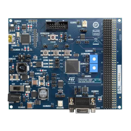
SPC574S-DISP Sphaero Discovery+
Introduction
This manual provides information to application developer on how to set and to use the SPC574S-DISP microcontroller
evaluation board.
UM2619 - Rev 1 - September 2019
www.st.com
For further information contact your local STMicroelectronics sales office.
Advertisement
Table of Contents

Related Manuals for ST SPC574S-DISP Sphaero Discovery+


Summary of Contents for ST SPC574S-DISP Sphaero Discovery+
- Page 1 SPC574S-DISP Sphaero Discovery+ Introduction This manual provides information to application developer on how to set and to use the SPC574S-DISP microcontroller evaluation board. UM2619 - Rev 1 - September 2019 www.st.com For further information contact your local STMicroelectronics sales office.
-
Page 2: Spc574S-Disp Discovery+ Board
• 12 V DC power supply (EU Plug). Free ready-to-run application firmware examples are available inside SPC5Studio (http//:www.st.com/spc5studio) to support a quick evaluation and development process. The PCB, the components and all the HW parts assembled in the board meet requirements of the applicable RoHS directives. -
Page 3: Debug Interface
UM2619 Debug interface Debug interface • 14-pins JTAG interface. • USB integrated programmer debugger. I/O interface and connectors • PSU plug (+12 V). • CAN with DB9 connector. • LIN and FlexRay, 2 pins. • UART (2x4 pin – not assembled). UM2619 - Rev 1 page 3/9... -
Page 4: Hardware Description
UM2619 Hardware description Hardware description Power supply section The external DC supply must be plugged in X1; the switch S1 allows to disconnect the external DC source. 2.1.1 External power supply The voltage regulators, U1 and U2 are used to generate 5 V and 1.2 V respectively. U3 provide 3.3 V. The LEDs LD1, LD2, LD3 and LD4 are all ON only when the power supply section works properly and the switch S1 is set in ON position. -
Page 5: User Leds
The integrated debugger SW is accessible via SPC5Studio (http//:www.st.com/spc5studio), a ST's free integrated development environment. To download the debugger software and to activate license refer to the PLS website. -
Page 6: Precautions
UM2619 Appendix A Precautions The following precautions are recommended when using the SPC574S-DISP: • Do not modify and not plug external parts or wires the board when it is supplied • Do not supply the board with AC source or with a DC source higher than 12 V. •... -
Page 7: Revision History
UM2619 Revision history Table 4. Document revision history Date Version Changes 24-Sep-2019 Initial release. UM2619 - Rev 1 page 7/9... -
Page 8: Table Of Contents
UM2619 Contents Contents SPC574S-DISP Discovery+ board ..........2 Debug interface . - Page 9 ST’s terms and conditions of sale in place at the time of order acknowledgement. Purchasers are solely responsible for the choice, selection, and use of ST products and ST assumes no liability for application assistance or the design of Purchasers’...
Need help?
Do you have a question about the SPC574S-DISP Sphaero Discovery+ and is the answer not in the manual?
Questions and answers