Table of Contents
Advertisement
UM1658
User manual
Discovery kit for STM32F030 Value Line microcontrollers
Introduction
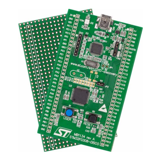
The STM32F030 Value Line Discovery kit (32F0308DISCOVERY) helps you to discover the
device features and to develop your applications easily. It is based on STM32F030R8T6, an
®
STM32 F0 series 32-bit ARM
Cortex™-M0 microcontroller, and includes an ST-LINK/V2
embedded debug tool, LEDs, push buttons and a prototyping board.
Figure 1. 32F0308DISCOVERY
September 2013
DocID025097 Rev 1
1/39
www.st.com
Advertisement
Table of Contents

Subscribe to Our Youtube Channel
Related Manuals for ST STM32F030


Summary of Contents for ST STM32F030
- Page 1 User manual Discovery kit for STM32F030 Value Line microcontrollers Introduction The STM32F030 Value Line Discovery kit (32F0308DISCOVERY) helps you to discover the device features and to develop your applications easily. It is based on STM32F030R8T6, an ® STM32 F0 series 32-bit ARM Cortex™-M0 microcontroller, and includes an ST-LINK/V2...
-
Page 2: Table Of Contents
Embedded ST-LINK/V2 ........ - Page 3 UM1658 List of tables List of tables Table 1. ON/OFF conventions ............5 Table 2.
- Page 4 ST-LINK connections image ........
-
Page 5: Conventions
UM1658 Conventions Conventions Table 1 provides the definition of some conventions used in the present document. Table 1. ON/OFF conventions Convention Definition Jumper JP1 ON Jumper fitted Jumper JP1 OFF Jumper not fitted Solder bridge SBx ON SBx connections closed by solder Solder bridge SBx OFF SBx connections left open DocID025097 Rev 1 5/39... -
Page 6: Quick Start
UM1658 Quick start The STM32F030 Value Line Discovery kit is a low-cost and easy-to-use development kit to quickly evaluate and start development with an STM32 F0 series microcontroller. Before installing and using the product, please accept the Evaluation Product License Agreement from www.st.com/stm32f0-discovery. -
Page 7: Features
STM32F030R8T6 microcontroller featuring 64 KB Flash, 8 KB RAM in an LQFP64 package • On-board ST-LINK/V2 with selection mode switch to use the kit as a standalone ST-LINK/V2 (with SWD connector for programming and debugging) • Board power supply: through USB bus or from an external 5 V supply voltage •... -
Page 8: Hardware And Layout
Hardware and layout UM1658 Hardware and layout The STM32F030 Value Line Discovery board is designed around the STM32F030R8T6 microcontroller in a 64-pin LQFP package. Figure 2 illustrates the connections between the STM32F030R8T6 and its peripherals (ST-LINK/V2, push button, LEDs and connectors). -
Page 9: Figure 3. Top Layout
UM1658 Hardware and layout Figure 3. Top layout (red/green LED) LD2 LD1 (red LED) ST-LINK/V2 5V power supply 3V power supply input output input output SWD connector ST-LINK/DISCOVERY selector IDD measurement SB1 (VDD) SB3 (B1-USER) B2 reset button STM32F030R8T6 SB4 (B2-RESET) -
Page 10: Figure 4. Bottom Layout
Hardware and layout UM1658 Figure 4. Bottom layout SB5, SB7, SB9, SB11 (RESERVED) SB6, SB8, SB10, SB12 (DEFAULT) SB13 (STM_RST) SB14, SB15 (RX, TX) SB16, SB17 (X2 crystal) SB18 (MCO) SB19 (NRST) SB20, SB21 (X3 crystal) SB22 (T_SWO) MS30025V1 10/39 DocID025097 Rev 1... -
Page 11: Stm32F030R8T6 Microcontroller
UM1658 Hardware and layout STM32F030R8T6 microcontroller The STM32F030R8T6 microcontroller incorporates the high-performance ARM Cortex™-M0 32-bit RISC core operating at a 48 MHz frequency, high-speed embedded memories (up to 64 Kbytes of Flash memory and up to 8 Kbytes of SRAM), and an extensive range of enhanced peripherals and I/Os. -
Page 12: Figure 6. Stm32F030R8T6 Block Diagram
Hardware and layout UM1658 Figure 6. STM32F030R8T6 block diagram Serial POWER DD18 SWCLK Wire VOLT.REG = 2.4 to 3.6 V SWDIO Debug 3.3 V TO 1.8 V as AF Flash up to 64 KB, CORTEX-M0 CPU SUPPLY 32 bits = 48 MHz HCLK Reset SUPERVISION... -
Page 13: Embedded St-Link/V2
Program/debug an MCU in an external application board using a cable connected to SWD connector CN3. The embedded ST-LINK/V2 supports only SWD for STM32 devices. For information about debugging and programming features refer to user manual UM1075 (ST-LINK/V2 in-circuit debugger/programmer for STM8 and STM32) which describes in detail all the ST-LINK/V2 features. -
Page 14: Using St-Link/V2 To Program/Debug The Stm32 F0 On Board
Hardware and layout UM1658 4.2.1 Using ST-LINK/V2 to program/debug the STM32 F0 on board To program the STM32 F0 on board, simply plug in the two jumpers on CN2, as shown in Figure 8 in red, but do not use the CN3 connector as that could disturb communication with the STM32F030R8T6 of the 32F0308DISCOVERY. -
Page 15: Using St-Link/V2 To Program/Debug An External Stm32 Application
Hardware and layout 4.2.2 Using ST-LINK/V2 to program/debug an external STM32 application It is very easy to use the ST-LINK/V2 to program the STM32 on an external application. Simply remove the 2 jumpers from CN2 as shown in Figure 9, and connect your application... -
Page 16: Power Supply And Power Selection
Slow blinking Red LED/Off: At power on before USB initialization – Fast blinking Red LED/Off: After the first correct communication between PC and STLINK/V2 (enumeration) – Red LED On: When initialization between PC and ST-LINK/V2 is successfully finished – Green LED On: After successful target communication initialization –... -
Page 17: Osc Clock
An external HSE clock can be provided to the MCU in three ways: • MCO from ST-LINK. From MCO of the STM32F103. This frequency cannot be changed, it is fixed at 8 MHz and connected to PF0-OSC_IN of the STM32F030R8T6. -
Page 18: Solder Bridges
SWO signal is not connected. No incidence on STM32F103C8T6 (ST-LINK/V2) NRST signal. SB13 (STM_RST) STM32F103C8T6 (ST-LINK/V2) NRST signal is connected to GND. BOOT0 signal of the STM32F030R8T6 MCU is held low through a 510 Ohm pull-down resistor. (BOOT0) BOOT0 signal of the STM32F030R8T6 MCU can be set high through a 10 KOhm pull-up resistor R27 to solder. -
Page 19: Extension Connectors
UM1658 Hardware and layout Extension connectors The male headers P1 and P2 can connect the 32F0308DISCOVERY to a standard prototyping/wrapping board. STM32F030R8T6 GPI/Os are available on these connectors. P1 and P2 can also be probed by an oscilloscope, logical analyzer or voltmeter. Table 5. - Page 20 Hardware and layout UM1658 Table 5. MCU pin description versus board function (continued) MCU pin Board function Main Alternate function functions SPI1_MISO, TIM3_CH1, TIM1_BKIN, TIM16_CH1, EVENTOUT, ADC_IN6 SPI1_MOSI, TIM3_CH2, TIM14_CH1, TIM1_CH1N, TIM17_CH1, EVENTOUT, ADC_IN7 USART1_CK, TIM1_CH1, EVENTOUT, USART1_TX, TIM1_CH2, TIM15_BKIN, I2C1_SCL USART1_RX, TIM1_CH3,...
- Page 21 UM1658 Hardware and layout Table 5. MCU pin description versus board function (continued) MCU pin Board function Main Alternate function functions SPI1_NSS, USART1_RX, PA15 USART2_RX, EVENTOUT TIM3_CH3, TIM1_CH2N, EVENTOUT TIM3_CH4, TIM14_CH1, TIM1_CH3N SPI1_SCK, EVENTOUT SPI1_MISO, TIM3_CH1, EVENTOUT SPI1_MOSI, I2C1_SMBA, TIM16_BKIN, TIM3_CH2 I2C1_SCL, USART1_TX,...
- Page 22 Hardware and layout UM1658 Table 5. MCU pin description versus board function (continued) MCU pin Board function Main Alternate function functions I2C1_SDA, PB11 I2C2_SDA, EVENTOUT SPI1_NSS, SPI2_NSS, PB12 TIM1_BKIN, EVENTOUT SPI1_SCK, PB13 SPI2_SCK, TIM1_CH1N SPI1_MISO, SPI2_MISO, PB14 TIM1_CH2N, TIM15_CH1 SPI1_MOSI, SPI2_MOSI, PB15 TIM1_CH3N,...
- Page 23 UM1658 Hardware and layout Table 5. MCU pin description versus board function (continued) MCU pin Board function Main Alternate function functions PC11 PC12 RTC_TAMP1, RTC_TS, PC13 RTC_OUT, WKUP2 PC14- OSC32_ OSC32_IN PC15- OSC32_ OSC32_OUT TIM3_ETR PF0- OSC_IN OSC_IN PF1- OSC_ OSC_OUT EVENTOUT EVENTOUT...
- Page 24 Hardware and layout UM1658 Table 5. MCU pin description versus board function (continued) MCU pin Board function Main Alternate function functions VSS_1 VSS_2 VSSA 24/39 DocID025097 Rev 1...
-
Page 25: Connecting Modules On The Prototyping Board
Connecting modules on the prototyping board This section gives some examples of how to connect ready-to-use modules available from different manufacturers to the STM32F030 Value Line Discovery kit via the prototyping board included in the kit. Software examples, based on the connections described below, are available at www.st.com/stm32f0-discovery. -
Page 26: Table 7. Connecting Using Idc10
Connecting modules on the prototyping board UM1658 Table 7. Connecting using IDC10 Mikroelektronica IDC10 connector 32F0308DISCOVERY GPIO GPIO OUTPUT (3.3V tolerant) GPIO GPIO OUTPUT (3.3V tolerant) GPIO GPIO OUTPUT (3.3V tolerant) GPIO GPIO OUTPUT (3.3V tolerant) GPIO GPIO OUTPUT (3.3V tolerant) GPIO GPIO OUTPUT (3.3V tolerant) GPIO... -
Page 27: Figure 10. Using Idc10 And Mikrobus™ Connectors
UM1658 Connecting modules on the prototyping board Figure 10 illustrates the connections between the 32F0308DISCOVERY and the 2 connectors, IDC10 and mikroBUS™. Figure 10. Using IDC10 and mikroBUS™ connectors DocID025097 Rev 1 27/39... -
Page 28: St Mems "Adapter Boards", Standard Dil24 Socket
SPI or I2C communications. Table 8 is one solution for connecting the DIL24 boards to the 32F0308DISCOVERY, this solution is used in different examples and available at www.st.com/stm32f0-discovery. Table 8. Connecting with a DIL24 board ST MEMS DIL24 Eval board... -
Page 29: Figure 11. Dil24 Socket Connections
UM1658 Connecting modules on the prototyping board Figure 11 illustrates the connections between the 32F0308DISCOVERY and the DIL24 socket. Figure 11. DIL24 socket connections DocID025097 Rev 1 29/39... -
Page 30: Table 9. Supported Mems Adapter Boards
Connecting modules on the prototyping board UM1658 Supported MEMS adapter boards Table 9 is a list of supported MEMS adapter boards as of April, 2012. Table 9. Supported MEMS adapter boards ST MEMS DIL24 Eval Board Core product STEVAL-MKI009V1 LIS3LV02DL STEVAL-MKI013V1 LIS302DL... -
Page 31: Arduino Shield Boards
LPS331AP] STEVAL-MKI125V1 A3G4250D Note: For an up-to-date list, visit http://www.st.com/internet/evalboard/subclass/1116.jsp. The DIL24 boards are described as “adapter boards” in the field “General Description”. Arduino shield boards Arduino™ is an open-source electronics prototyping platform based on flexible, easy-to-use hardware and software. See http://www.arduino.cc for more information. -
Page 32: Figure 1. 32F0308Discovery
Connecting modules on the prototyping board UM1658 Table 10. Connecting with Arduino shields (continued) Arduino digital connector 32F0308DISCOVERY Digital pin 0 or RX USART2_RX Digital pin 1 or TX USART2_TX Digital pin 2 / External interrupt PB12 EXTI (5V tolerant) Digital pin 3 / Ext int or PWM PB11 EXTI (5V tolerant) or TIM2_CH4... -
Page 33: Figure 12. Arduino Shield Board Connections
UM1658 Connecting modules on the prototyping board Figure 12 illustrates the connections between the 32F0308DISCOVERY and the Arduino shield boards. Figure 12. Arduino shield board connections DocID025097 Rev 1 33/39... -
Page 34: Mechanical Drawing
Mechanical drawing UM1658 Mechanical drawing Figure 13. 32F0308DISCOVERY mechanical drawing MB1134 revA STM32F0308-DISCO 34/39 DocID025097 Rev 1... -
Page 35: Electrical Schematics
UM1658 Electrical schematics Electrical schematics Figure 14. 32F0308DISCOVERY DocID025097 Rev 1 35/39... -
Page 36: Figure 15. St-Link/V2 (Swd Only)
Electrical schematics UM1658 Figure 15. ST-LINK/V2 (SWD only) 36/39 DocID025097 Rev 1... -
Page 37: Figure 16. Mcu
UM1658 Electrical schematics Figure 16. MCU SW-PUSH-CMS SW-PUSH-CMS DocID025097 Rev 1 37/39... -
Page 38: Revision History
Revision history UM1658 Revision history Table 11. Document revision history Date Revision Changes 03-Sep-2013 Initial release. 38/39 DocID025097 Rev 1... - Page 39 No license, express or implied, by estoppel or otherwise, to any intellectual property rights is granted under this document. If any part of this document refers to any third party products or services it shall not be deemed a license grant by ST for the use of such third party products or services, or any intellectual property contained therein or considered as a warranty covering the use in any manner whatsoever of such third party products or services or any intellectual property contained therein.
- Page 40 Mouser Electronics Authorized Distributor Click to View Pricing, Inventory, Delivery & Lifecycle Information: STMicroelectronics STEVAL-MKI084V1...
Need help?
Do you have a question about the STM32F030 and is the answer not in the manual?
Questions and answers