Table of Contents
Advertisement
Quick Links
UM1657
User manual
SPIRIT1 development kit
Introduction
The SPIRIT1 DK is a complete software package to support SPIRIT1 RF evaluation and
development. It contains a SPIRIT1 DK GRAPHICAL USER INTERFACE (SPIRIT1 DK -
GUI) which allows checking the SPIRIT1 main performance and easily measure parameters
such as sensitivity, output power and main features of the SPIRIT1. It also contains SPIRIT1
firmware libraries for STM32L and STM8L to allow development of SPIRIT1 applications. In
addition, it contains a Wireless M-BUS library with documentation and example applications
to allow development of Wireless M-BUS application based on the SPIRIT1.
November 2013
DocID025094 Rev 1
1/48
www.st.com
Advertisement
Table of Contents

Related Manuals for ST SPIRIT1


Summary of Contents for ST SPIRIT1
- Page 1 GUI) which allows checking the SPIRIT1 main performance and easily measure parameters such as sensitivity, output power and main features of the SPIRIT1. It also contains SPIRIT1 firmware libraries for STM32L and STM8L to allow development of SPIRIT1 applications. In addition, it contains a Wireless M-BUS library with documentation and example applications to allow development of Wireless M-BUS application based on the SPIRIT1.
-
Page 2: Table Of Contents
Software installation ........24 SPIRIT1 DK - GUI description ....... . . 26 Firmware installation . - Page 3 Help ........... . 40 SPIRIT1 WM-BUS GUI description ......41 Firmware installation .
- Page 4 List of tables UM1657 List of tables Table 1. MCU pin description versus board function ........7 Table 2.
- Page 5 SWD connection scheme with ST-LINK/V2 ........
-
Page 6: Hardware Description
(with x = 2, 3, 4, 5). STEVAL-IKR002Vx The SPIRIT1 DK is made up of two units connected to one PC or two PCs with USB cables. Each unit is composed of an antenna for the selected band and two PCBs: ... -
Page 7: Microcontroller And Connections
UM1657 Hardware description Figure 1. STEVAL-IKR002Vx (RF motherboard) 1.1.2 Microcontroller and connections The board has an STM32L151RB microcontroller. It's an ultralow power microcontroller with 128 KB of flash memory, 16 KB of RAM, 32-bit core ARM cortex-M3, 4 KB of data EEPROM, RTC, LCD, timers, USART, I²C, SPI, ADC, DAC and comparators. - Page 8 Hardware description UM1657 Table 1. MCU pin description versus board function (continued) Board function Pin name Pin n° Temperat Buttons / Accelerome Ext. LEDs DB connector JTAG Joystick conn. sensor VSSA VDDA VSS_4 VDD_4 SPI1_NSS SPI1_SCK SPI1_MISO SPI1_MOSI LED4 LED5 JOY_DOW JOY_RIG PB10...
-
Page 9: Power
UM1657 Hardware description Table 1. MCU pin description versus board function (continued) Board function Pin name Pin n° Temperat Buttons / Accelerome Ext. LEDs DB connector JTAG Joystick conn. sensor JOY_LEFT JOY_CEN PA10 JOY_UP USB_D PA11 USB_D PA12 PA13 JTMS VSS_2 VDD_2 PA14... -
Page 10: Sensors
4 possible positions (left, right, up, down) (G in Figure 1.1.8 JTAG connector A JTAG connector on the board (H in Figure 1) allows programming and debugging of the STM32L microcontroller on board, using an in-circuit debugger and programmer like the ST- LINK/V2. 10/48 DocID025094 Rev 1... -
Page 11: Leds
Figure 2, allows connection with RF instruments as spectrum analyzer and signal generator to the SPIRIT1 by RF cable or also connect an antenna as the one included in the demo kit. The board is powered through the RF daughterboard connector, in D... -
Page 12: Boost Mode
1.2.1 Boost mode The SPIRIT1 can be configured to increase the output power in transmission mode. In the default configuration the transmitter power amplifier (PA) output is biased by the 1.4 V SMPS voltage output through the L0 external inductor (position D0 in the schematic, 3). -
Page 13: Figure 3. Steval-Ikr002Vx (Rf Module) Boost Mode Configuration
Figure 3. STEVAL-IKR002Vx (RF module) boost mode configuration For more information see the application note AN4198 - SPIRIT1: increasing the output power, available on the SPIRIT1 web site or in the document folder of this release. DocID025094 Rev 1 13/48... -
Page 14: Steval-Ikr001V7D
RF instruments as spectrum analyzer and signal generator to the SPIRIT1 by RF cable or also connect an antenna as the one included in the demo kit. The board is powered through the RF daughterboard connector, in... -
Page 15: Steval-Ikr001V8D
RF instruments as spectrum analyzer and signal generator to the SPIRIT1 by RF cable or also connect an antenna as the one included in the demo kit. The board is powered through the RF daughterboard connector, in A... -
Page 16: Steval-Ids001Vx (Spirit1 Usb Dongle)
A strip line can be soldered, in B Figure 6, allowing the access to the SWD interface for programming and debugging and to the 4 GPIOs of the SPIRIT1. The board can be powered through the USB connector, in A Figure 6, that can also be used for I/O interaction with a USB Host. -
Page 17: Table 2. Mcu Pin Description Versus Board Function
UM1657 Hardware description Table 2. MCU pin description versus board function Board function Pin name Pin n° Ext. LEDs SPIRIT1 Buttons conn. VLCD VBAT PC13 SDN_SPIRIT1 PC14 PC15 OSC_IN OSC_OUT NRST VSS_A VDD_A USER_BUTTON_2 USER_LED_2 USER_LED_1 USER_BUTTON_1 PB10 GPIO3_SPIRIT1 PB11... -
Page 18: Extension Connector
6. The SWD interface allows programming and debugging of the STM32L microcontroller on board, using an in-circuit debugger and programmer like the ST-LINK/V2. In Figure 7 the connection scheme to how connect the ST-LINK/V2 with the board pins is showed. 18/48 DocID025094 Rev 1... -
Page 19: Table 3. Swd Connection
SWDIO. SWO/TRACE. SWCLK. SPIRIT1 GPIO0. SPIRIT1 GPIO1. SPIRIT1 GPIO2. 10. SPIRIT1 GPIO3. The connection with the ST-LINK/V2 interface is the following, as showed in Figure Table 3. SWD connection Signal name STEVAL-IDS001Vx pin number ST-LINK/V2 pin number nRESET SWDIO... -
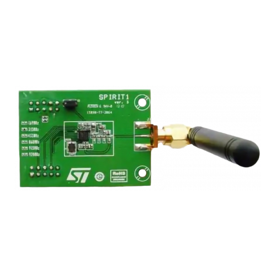
Page 20: Band
Hardware description UM1657 1.5.4 Band The STEVAL-IDS001Vx has 4 different possible BOM lists, each one optimized for different RF band as follow: 315 MHz 433 MHz 868 MHz 915 MHz The chip antenna used supports all these four bands of frequency. 1.5.5 RF connector The STEVAL-IDS001Vx provides two different RF connections: antenna (chip antenna... -
Page 21: Leds
– D2: green. STEVAL-IKR001Vx The SPIRIT1 DK is made up of two units connected to one PC or two PCs with USB cables. Each unit is composed of an antenna for the selected band and two PCBs: RF motherboard ... - Page 22 Push_Button, used to enter in DFU mode Joystick, not used. Test point (TP), to probe the SPI signals, the 4 GPIOs of the SPIRIT1, the shutdown of the SPIRIT1 (SDN), the supply voltage of the SPIRIT1 (VCCRF). The list of signals...
-
Page 23: Steval-Ikr001Vx (Rf Module)
Figure 10, allows connection with RF instruments as spectrum analyzer and signal generator to the SPIRIT1 by RF cable or also connect an antenna as the one included in the demo kit. The board is powered through the RF daughterboard connector, in D... -
Page 24: Figure 10. Steval-Ikr001Vx (Rf Module)
Hardware description UM1657 Figure 10. STEVAL-IKR001Vx (RF module) 24/48 DocID025094 Rev 1... -
Page 25: Software Installation
Software installation Software installation The SPIRIT1 DK comes as a self-installer file which will take care of installing all the necessary files in the user PC. To begin the installation the user must double click on the installer file and follow the instructions. -
Page 26: Figure 12. Spirit Dk - Driver Installation Window
Figure 12. SPIRIT DK - driver installation window The user may install the driver also manually make run the "DPInst_x86.exe" or "dpinst_ia64.exe" in "\SPIRIT1 DK\Driver" folder. At first connection of the SPIRIT DK - MB, the user is required to select the proper driver. -
Page 27: Spirit1 Dk - Gui Description
Detailed description The SPIRIT1 DK - GUI can use only one SPIRIT1 DK - MB plus SPIRIT1 RF - DB plugged on it, connected through a USB cable to a PC. So, it is necessary to run one instance of SPIRIT1 DK - GUI for each board connected to the PC. -
Page 28: Connection Panel
At the top of the main window, the user can select the appropriate COM from a drop down list of the COM port available. Once the correct SPIRIT1 DK - DB COM port is selected, and the "Open" button pressed, the LED4 (blue led) of the SPIRIT1 DK - MB turn on and the default configuration of SPIRIT1 DK - DB is loaded and dis-played on the SPIRIT1 DK - GUI. -
Page 29: Supply Voltage Panel
Supply voltage panel (supported only in STEVAL-IKR001Vx - RF motherboard) At the top right of the main window, the user can read supply voltage of the SPIRIT1 DK - DB. This voltage can be also read by the pin VCCRF on the SPIRIT1 DK - MB. -
Page 30: Rf Test Mode
Otherwise, if the AUTO check box is not checked, the user must write the correct XTAL frequency value. By pressing the "Configure radio" button, all the values are sent to the SPIRIT1 DK - DB and then read and dis-played for the user. -
Page 31: Packet Setting
The user can measure the output signal at the suitable SMA connector or the TX state current consumption. The SPIRIT1 DK - DB stays in state TX until the "TX PN9 STOP" button is pressed. When the user wants to change the frequency or output power or modulation scheme, the running test must be stopped first and then repeat steps 1 and 2 selecting the desired frequency or output power or modulation scheme during step 1. -
Page 32: Packet Setting - Basic
"Data whitening". 3.2.9 Packet setting - WMBUS As shown in Figure 22, selecting MBUS, SPIRIT1 DK - DB uses the packet format MBUS described in the datasheet. The options for the packet are: MBUS submode. Preamble length. -
Page 33: Transmission Test
UM1657 SPIRIT1 DK - GUI description Using this packet setting, the transmitter builds the frame with a length field of one byte, and then adds the data blocks with CRC included. The GUI shows the frame received with the length field and the CRC field for each data blocks. - Page 34 This period is necessary only during the RX state to allow the SPIRIT1 find correctly a SYNC word. If the value is 0, then the RX timeout is infinite and the SPIRIT1 stays in RX state until it found a correct SYNC word.
-
Page 35: Aes
UM1657 SPIRIT1 DK - GUI description The button "Sense RSSI" can be used to read the RF power on air according to the center frequency and the channel filter bandwidth configured. This feature allows knowing also the RF noise in the environment. -
Page 36: Low Level Commands
SPIRIT1 DK - GUI description UM1657 Select "Derive decryption key" in AES operation Type the encryption key composed of 128 bits (i.e. 32 hex chars) in the Key field Push "START AES OPERATION" button The derived decryption text is provided as 32 hex chars in Data output The Decryption using a decryption key operation is performed following these steps: Select "Decryption using a given decryption key"... -
Page 37: How Run A Ber Test Using Signal Generator
To write a register of the SPIRIT1 is necessary to write the address of the register to modify and the new value of the register. All the registers of the SPIRIT1 can be read and saved in a text file by clicking the Save button of the "Save register value" panel. -
Page 38: Tools
SPIRIT1 DK - GUI description UM1657 Figure 25. BER test using SPIRIT1 DK - GUI Tools Figure 26. Tools list Opening the tools list a set of options are available to the user to check and update firmware and also to load and save radio configurations. -
Page 39: Firmware Upgrade
SPIRIT1 DK - GUI description 3.4.2 Firmware upgrade The SPIRIT1 DK is shipped with a firmware which allows performing automatic firmware upgrade via the USB port. The default firmware is composed of two applications: DFU boot loader which allows to perform firmware upgrade ... -
Page 40: Help
SPIRIT1 DK - GUI description UM1657 3.4.4 Help Figure 27. Help with user manual Opening the Help list a link to the user manual is available. 40/48 DocID025094 Rev 1... -
Page 41: Spirit1 Wm-Bus Gui Description
Detailed description The SPIRIT1 Wireless M-BUS - GUI requires only the concentrator to be connected with the PC, the meter is operated through joystick and buttons and it needs USB connection just for power. -
Page 42: Figure 28. Wm-Bus Gui Step 2
SPIRIT1 WM-BUS GUI description UM1657 Figure 28. WM-BUS GUI step 2 Figure 29. WM-BUS GUI step 2 (successful connection) 42/48 DocID025094 Rev 1... -
Page 43: Figure 30. Wm-Bus Gui Step 3 And 4
UM1657 SPIRIT1 WM-BUS GUI description Figure 30. WM-BUS GUI step 3 and 4 Figure 31. WM-BUS GUI step 7 DocID025094 Rev 1 43/48... -
Page 44: Figure 32. Wm-Bus Gui Step 9, 11
SPIRIT1 WM-BUS GUI description UM1657 Figure 32. WM-BUS GUI step 9, 11 44/48 DocID025094 Rev 1... -
Page 45: Spirit1 Driver And Example Programs
UM1657 SPIRIT1 driver and example programs SPIRIT1 driver and example programs The installed software package contains also support for SPIRIT1 firmware development. The directory tree includes: SPIRIT1 driver in source form for STM32L Example IAR projects for STM32L in: –... -
Page 46: Spirit1 Wireless M-Bus Library And Example Programs
SPIRIT1 wireless M-BUS library and example programs UM1657 SPIRIT1 wireless M-BUS library and example programs The installed software package contains also support for SPIRIT1 Wireless M-BUS firmware development. The directory tree includes: SPIRIT1 Wireless M-BUS library driver in binary form for STM32L ... -
Page 47: Revision History
UM1657 Revision history Revision history Table 5. Document revision history Date Revision Changes 28-Nov-2013 Initial release. DocID025094 Rev 1 47/48... - Page 48 No license, express or implied, by estoppel or otherwise, to any intellectual property rights is granted under this document. If any part of this document refers to any third party products or services it shall not be deemed a license grant by ST for the use of such third party products or services, or any intellectual property contained therein or considered as a warranty covering the use in any manner whatsoever of such third party products or services or any intellectual property contained therein.
Need help?
Do you have a question about the SPIRIT1 and is the answer not in the manual?
Questions and answers