
Related Manuals for Hioki SM-8216


Summary of Contents for Hioki SM-8216
- Page 1 Instruction Manual SM-8216 SUPER MEGOHMMETER November 2010 Revised edition 2 SM8216A981-02 10-11H...
- Page 3 1. Safety Precautions Operators of the SM-8216 super megohmmeter are requested to read this operation manual thoroughly before operation for safety and to obtain best performance. Operators are also requested to strictly observe all the DANGER, WARNING, and CAUTION notices in this manual and on the instrument to prevent injury and damage.
- Page 4 Congratulations on your purchase of a HIOKI SM-8216 super megohmemeter. The super megohmmeter is a unique analog resistance meter designed to measure high resistance in a wide range. The MS-8216 meter outputs a high test voltage – 1000 V maximum to apply across the sample circuit.
- Page 5 1.2 Symbols on the Super Megohmmeter Symbol Meaning Description This symbol is shown at pats whose WARNING usage needs reference to the operation manual. This symbol is shown at the Rx ‘–‘/’+’ DANGER – Measuring terminals which carry HIGH VOLTAGE high voltage to be applied across the HAZARD circuit to be measured.
- Page 6 ■ Do not operate the super megohmmeter in the presence of flammable gas. There is s possibility of an explosion and/or fire. ■ Do not touch the Rx ‘–‘/’+’ measuring terminals on the front panel of the SM-8216 during measurement. They output a maximum measuring voltage of 1000 V. WARNING ■ ...
- Page 7 ■ If the instrument generates smoke or smell, unplug the power cord. If such an instrument is kept powered on, it may cause a fire. Contact your local HIOKI Electronics distributor for repair. ■ Do not operate the instrument with a wet hand. This may cause electrical shock.
- Page 8 The resistance measuring ranges of the SM-8216 is as follows: 5.0×10 to 2×10 Ω The SM-8216 super megohmmeters is provided with a large analog meter for easy reading of a measured insulation resistance. The following shows the main specifications for the SM-8216. For detailed specifications, see 2. SPECIFICATIONS.
- Page 9 This section describes precautions for unpacking and AC line voltage setting. 2. SPECIFICATIONS This section describes the specifications for the SM-8216 super meg- ohmmeters and optional accessories. 3. OPERATING PRINCIPLE This section describes the operating principle with a block diagram of the SM-8216.
- Page 10 viii...
-
Page 11: Table Of Contents
CONTENTS 1. PREPARATION BEFORE OPERATION ..... . . 1 1 1 1 1.1 Unpacking and Checking of the Contents ....1 1... - Page 12 8. MAINTENANCE AND MISCELANEOUS ..... .2 9 2 9 2 9 2 9 8.1 Periodical Checking ....... . . 2 9 2...
-
Page 13: Preparation Before Operation
1. PREPARATION BEFORE OPERATION 1.1 Unpacking and Checking of the Contents When you have received the carton of the SM-8216 super megohmmeter, carefully unpack it, and take out every thing from the carton. Although the instrument and its accessories are severely inspected before shipment from factory, visually check the items and their quantities. -
Page 14: Operating Ac Line Voltage
1.2 Operating AC Line Voltage The super megohmemeter can be operated from one of the following AC power source when the LINE SELECTOR switches are set accordingly. AC Line Voltage Frequency 100 V ±10% 50/60 Hz 120 V ±10% 50/60 Hz 220 V ±10% 50/60 Hz 240 V +10V, ‑10%... -
Page 15: Checking The Fuse Amperage
LINE SELECTOR 100V 120V 220V 240V Fig. 1.1.1 LINE SELECTOR Switch Setting The super megohmmeter can be operated from one of the following AC power source when the LINE SELECTOR switches are set accordingly. LINE SELCTOR Setting Acceptable Line Voltage Range 100 V 90 V to 110V (100 V ±10%) -
Page 16: Grounding The Chassis
Fuse Replacement The fuse is inserted in the FUSE holder (Fig. 1.1.2) on the rear of the unit. Remove the cap, and replace the fuse with a new one with a correct amperage. To remove the cap of the fuse holder, use a 4 mm Phillips screwdriver, and turn the cap counterclockwise. -
Page 17: Warm-Up Period
1.6 Warm-up Period To obtain the performance of published specifications, allow the SM-8200 Series super megohmmeter to warm for a minimum of 30 minutes. -
Page 18: Specifications
2. SPECIFICATIONS 2.1 Measuring Performance Insulation Resistance Measurement (RANGE : ×1 , ×10 , ×10 , ×10 , ×10 , or ×10 Target Voltage Measurement Range (MΩ ) [RANGE=×10 × 10 to 200 × 10 1000 V 500 V × 10 to 100 ×... -
Page 19: Optional Functions And Accessories
Either one of the RP-8000 or RI-8000 optional function can be installed in a single SM-8216 unit. The RP-8000/RI-8000 optional function is available on factory- installation basis, only. 2) Options – designed for common to the SM-8216, SM-8200 Series, and SM-8000 Series super megohmmeters. Name Model... - Page 20 SME-8335 Capacity, approx. 30 mL Liquid sample Electrode constant: Approx. Measurement 75 cm Electrodes for chip SME-8360 Chip capacitor measurement Capacitors Other types of optional electrodes and devices are available upon request. For details, contact your local HIOKI Electronics distributor.
- Page 21 3. OPEARATING PRINCIPLE The SM-8216 super megohmmeters consist of a constant voltage power supply and a high sensitive current measuring section to be combined to compose a resistance measuring circuit. The current measuring section is composed of a current detective resistor, And low drift voltage amplifier.
-
Page 22: Familiarization With Controls And Parts
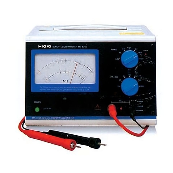
4. FAMILIARIZATION WITH CONTROLS AND PARTS 4.1 Front Panel The figure below shows the front panel of the SM-8216. ① ⑨ ⑦ ⑥ ⑤ ② ③ ⑧ ④ Fig. 4.1.1 Front Panel ① Indicating Meter: This meter has a multi-scale to indicate a wide range of measured insulation resistance values. ... - Page 23 ④ Rx ‘‑‘/’+’ Measuring Terminals: These terminals carry a selected measuring voltage across them to measure the insulation resistanceof a sample via a pair of measuring rods or electrodes. The polarity of the terminals is as follows: Rx ’–‘ measuring terminal: Red measuring rod Rx ‘+’...
- Page 24 ⑦ RANGE Selector Switch: This switch selects the factor to be multiplied to the measured value shown with the indicating meter. The CAL position is used for calibration. For details of the calibration procedures, see 5. PREPARATION FOR A MEASUREMENT.
-
Page 25: Rear Panel
4.2 Rear Panel The figure below shows the rear panel of the SM-8216. However, note that the LINE SELECTOR switches are set for the operation from 100 V AC line. ⑩ ⑪ ... - Page 26 If such a switch is not provided, keep this connector plugged with the accessory shorting plug, instead. ⑭ OUT/BUZZER Selector Switch: This switch selects the mode of alarm output – to the buzzer or relay contacts when the AL-8000 optional alarm device is installed.
-
Page 27: Preparation For A Measurement
5. PREPARATION FOR A MEASUREMENT WARNING Before connecting the power cord to the AC outlet socket, confirm that the LINE SELECTOR switches on the rear panel are set to the positions, accordingly (See 1.3 Setting the LINE SELETOR Switches.). If the switches are set to wrong positions, a fire or burn may occur. WARNING To prevent an accident, connect the ground prong of the power cord plug to the ground post of the AC line system. - Page 28 3) AC Power Line Connection (5) Confirm that the LINE SELECTOR switches are set to the positions in accordance with the local AC line voltage. If necessary, refer to 1.3 Setting the LINE SELECTOR Switches. (6) Confirm that the POWER switch is set to OFF (released position). Note: If the switch is in the pushed position, it is set to ON.
- Page 29 8) Setting the Measuring Voltage (21) Set the VOLTAGE selector switch to the position in accordance with your measurement program. (22) If there is no idea about the measuring voltage to use, set the VOLTAGE selector to the lowest voltage available (10 V) to try the first measurement, then, increase the voltage in response with the result of the measurement.
-
Page 30: Measurement
2) The black measuring rod (connected to the Rx ‘+‘ terminal) is connected to the chassis (ground) of the SM-8216 unit. This design makes it possible, when measuring the insulation resistance of a shielded wire sample between its conductor and... - Page 31 1) Measurement Using the Measuring Voltage Output without Interruption This is a basic and practical measuring me thod. Note: With this measuring me thod, the red measuring rod tip carries the measuring voltage without interruption. This can cause an electrical shock if the operator handles the measuring rods without care.
- Page 32 (4) After completion of the measurement, se t the function selector to the DISCHARGE position to discharge and disarm the sample. Notes: 1) Use utmost care to read the indicated value on the meter because the the indicating meter of the instrument has a multi-scale. The full ...
-
Page 33: Interlocking Function - Using The Hv-En Connector
Me a s u r in g R od ( R ed ) SM-8216 Re s is tan ce f or S a m p l e t o D i sc h a rg e Me as u r e ( Ap p r o x. -
Page 34: Calibration Function
5.05 of the 1000 V scale, the calibration is successfully done. If the me ter needle deflection is out of the said range, the internal adjustments need readjustment or a failure of the unit is suspected. Contact your local HIOKI Electronics distributor for technical advice. -
Page 35: Changes In The Current Flowing Through An Insulator
6.5 Changes in the Current Flowing through an Insulator In insulation resistance measurements, a large amount of current flows Upon the application of the measuring voltage to the insulator. The current gradually reduces its value with time, but it takes a time until the value becomes stable and fixed. - Page 36 measurements, it takes several hours to a few days for the leakage current to stabilize. This is not practical. To avoid this problem, a method is customarily used in the insulation resistance measurement for convenience to read the resistance value one minute after charging the test voltage to the sample.
-
Page 37: Dc Signal Outputs
7. OPTIONAL ACCESSORIES With the SM-8216, SM-8200 Series and SM-8000 Series super megohmme ters, any of the following options can be provided as needed. However, note that some of them can be installed at factory, only. 7.1 DC Signal Outputs Either one of two different types of DC signal outputs can be optionally installed with the unit at factory. - Page 38 3) Output voltage These tables show the relations between displayed value of SM-8216 super megohmmeter and output voltage of RP-8000. Target voltage 10V 0.05...
- Page 39 -- R -- is doubled. This relation can be expressed as “1/R.” The RI-8000 provides this type of DC signal output. 1) Specifications Output Range: Full range of the measuring range of the SM-8216 super megohmmeter Output Voltage: 10V/minimum value of each range of...
- Page 40 2) output voltage These tables show the relations between displayed value of SM-8216 super megohmmeter and output voltage of RI-8000. Target voltage 10V 0.05 Displayed value Output voltage Target voltage 25V 0.125 0.25 1.25 Displayed value Output voltage Target voltage 50V 0.25...
- Page 41 8.2 Storage, Transportation and Abandon 1) Storage When the SM-8216 unit is shutdown for a long period of time, unplug the power cord from the AC line outlet, put a dust cover over it, and store the unit in a place meeting the following conditions.
- Page 42 9. EXTERNAL APPEARANCE 190(H) Unit: mm...
- Page 44 HIOKI USA CORPORATION 6 Corporate Drive, Cranbury, NJ 08512, USA TEL +1-609-409-9109 FAX +1-609-409-9108 Edited and published by Hioki E.E. Corporation Technical Support Section • All reasonable care has been taken in the production of this manual, but if you find any points which are unclear or in error, please contact your supplier or the International Sales and Marketing Department at Hioki headquarters.
Need help?
Do you have a question about the SM-8216 and is the answer not in the manual?
Questions and answers