Table of Contents
Advertisement
SM7110
SM7120
SUPER MEGOHM METER
Be sure to read this manual before
using the instrument.
When using the instrument
for the first time
Names and Functions of Parts
Preparing for Measurement
Nov. 2018 Revised edition 3
SM7110A961-03 18-11H
p.18
p.29
Instruction Manual
Safety information
Operating Precautions
Troubleshooting
Maintenance and Service
Error display and solution
p.6
p.9
p.157
p.160
EN
Advertisement
Table of Contents

Related Manuals for Hioki Super megohm SM7110


Summary of Contents for Hioki Super megohm SM7110
- Page 1 SM7110 SM7120 Instruction Manual SUPER MEGOHM METER Safety information Be sure to read this manual before using the instrument. Operating Precautions p.9 When using the instrument Troubleshooting for the first time p.18 p.157 Names and Functions of Parts Maintenance and Service ...
- Page 3 Contents Introduction ..........1 Setting Measurement Speed ..43 Verifying Package Contents ..... 2 Changing Current Range ....44 Measurement Procedure......5 Connecting Measurement Leads Safety Information ........6 or Electrode to Object to Be Operating Precautions ......9 Measured ........45 Starting/Stopping Measurement ........
- Page 4 Contents Browsing, Deleting, and Measurement Methods Outputting Internal Memory Data 101 Suitable for Various „ Browsing and deleting data ......102 Objects to Be Measured 77 Checking Voltage Error (Voltage Monitor Check Function) 103 Preventing Test From Being Measuring Components or Incorrectly Started Circuits ..........
- Page 5 Contents Appx. 3 Sample calculation of Communications (USB, resistance measuring RS-232C, GP-IB) accuracy (SM7110) ... Appx.3 Appx. 4 Countermeasures 10.1 Summary and Features of Against Noise ....Appx.4 Interface ........129 Appx. 5 Using Instrument as 10.2 USB Interface ........ 130 Ammeter (If Operated „...
- Page 6 Contents...
- Page 7 Introduction Introduction Thank you for purchasing the Hioki SM7110/SM7120 Super Megohm Meter. To obtain maximum performance from the instrument, please read this manual first, and keep it handy for future reference. Trademark • Adobe and Adobe Reader are trademarks of Adobe Systems Incorporated.
-
Page 8: Verifying Package Contents
When you receive the instrument, inspect it carefully to ensure that no damage occurred during shipping. In particular, check the accessories, panel switches, keys, and connectors. If damage is evident, or if it fails to operate according to the specifications, contact your authorized Hioki distributor or reseller. - Page 9 Verifying Package Contents Options The following options are available for the instrument. Contact your authorized Hioki distributor or reseller when ordering. Measurement leads See p. 11. Model L2230 Pin Type Lead (Red) Model L2231 Pin Type Lead (Black) Length: Length:...
- Page 10 Verifying Package Contents Electrodes Conversion of the connectors is required to connect these electrodes. Contact your authorized Hioki distributor or reseller. Model SME-8301 Surface Resistance Model SME-8302 Electrode for Surface Measurement Electrode Resistance Model SME-8310 Plate Sample Electrode Model SME-8311 Electrode for Flat Sample...
-
Page 11: Measurement Procedure
Measurement Procedure Measurement Procedure Be sure to read “Operating Precautions” (p. 9) beforehand. Installing, connecting, and turning on the instrument Install the instrument. (p. 10) Connect the measurement lead and electrode to the instrument. Connect the power cord to the instrument. (p. 29) Connect the measurement lead, electrode, and the Turn on the instrument. -
Page 12: Safety Information
Safety Information Safety Information This instrument is designed to conform to IEC61010 Safety Standards, and has been thoroughly tested for safety prior to shipment. However, using the instrument in a way not described in this manual may negate the provided safety features. Before using the instrument, be certain to carefully read the following safety notes: DANGER Mishandling during use could result in injury or death, as well as damage to the... -
Page 13: Symbols On The Instrument
Safety Information Symbols on the instrument Indicates cautions and hazards. When the symbol is printed on the instrument, refer to a corresponding topic in the Instruction Manual. Indicates that dangerous voltage may be present at this terminal. Indicates the ON side of the power switch. Indicates the OFF side of the power switch. -
Page 14: Measurement Categories
Safety Information Measurement categories To ensure safe operation of measuring instruments, IEC61010 establishes safety standards for various electrical environments, categorized as CAT II to CAT IV, and called measurement categories. DANGER • Using a measuring instrument in an environment designated with a higher- numbered category than that for which the instrument is rated could result in a severe accident, and must be carefully avoided. -
Page 15: Operating Precautions
• Verify that the instrument operates normally to ensure that no damage occurred during storage or shipping. If you find any damage, contact your authorized Hioki distributor or reseller. To prevent an electric shock, confirm that the braided conductor for shielding wire is not exposed. - Page 16 Operating Precautions Installing the instrument To prevent overheating, be sure to leave the specified clearances around the instrument. • Install with the bottom surface facing downward. • Vents must not be obstructed. 10 mm or more 50 mm or more 50 mm or more Rear 15 mm or more...
- Page 17 Operating Precautions Before connecting the power cord to the instrument DANGER Use only the designated power cord with this instrument. Use of other power cords may cause fire. WARNING • Before turning the instrument on, make sure the supply voltage matches that indicated on its power connector.
- Page 18 Operating Precautions Before connecting the measurement leads or electrode to an object to be measured WARNING Between either of the following terminals, a maximum voltage of 1000 V may be generated depending on the measurement voltage settings. • Between the OUTPUT terminal and the INPUT terminal •...
- Page 19 Operating Precautions Before performing an automatic measurement CAUTION To protect the relay contacts, switching the measurement terminals with relays leaving a measurement voltage output requires a protective resistor* inserted in series in the circuit. Protective resistance value ≥ (Measurement voltage) / (Maximum allowable current) * Implements resistance to prevent the current flowing through the contact from exceeding the maximum allowable current of the contact...
- Page 20 Operating Precautions CAUTION You must not operate the EXT I/O MODE switch (NPN/PNP) during the instrument turned on. Select the external I/O mode between NPN and PNP based on devices that are externally connected (p. 110). Before connecting the communication cable to the instrument DANGER To avoid electrical hazards and damage to the instrument, do not apply voltage exceeding the rated maximum to the EXT I/O terminal.
- Page 21 • Keep discs inside a protective case and do not expose to direct sunlight, high temperature, or high humidity. • Hioki is not liable for any issues your computer system experiences in the course of using this disc.
- Page 22 Operating Precautions...
-
Page 23: Product Overview And Features
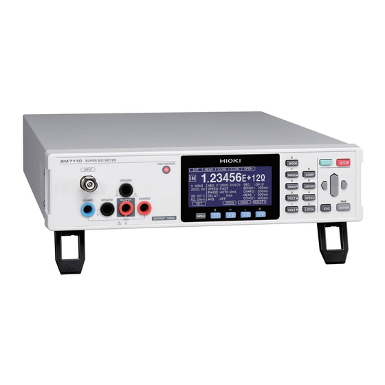
Overview 1.1 Product Overview and Features This instrument is an insulation resistance meter containing a highly sensitive ammeter and a low- noise voltage supply. Employing the triaxial BNC connector enables the instrument to measure high resistance such as resistance of insulators with no influence of exogenous noise. The maximum measurement voltages of Model SM7120 and Model SM7110 are 2000 V and 1000 V, respectively. -
Page 24: Names And Functions Of Parts
Names and Functions of Parts 1.2 Names and Functions of Parts Front The model illustrated below is Screen Model SM7120. Monochrome graphic LCD HIGH VOLTAGE LED Lights up while a high voltage Operation keys (p. 21) is output. Measurement terminals Connect measurement leads to these terminals. - Page 25 Names and Functions of Parts Measurement Description terminal This is a charge voltage output terminal. Used to pre-charge objects before measurement. The pre-charge voltage is output between the CHARGE terminal and the GROUND CHARGE terminal. The voltage is same as the measurement voltage. The CHARGE terminal has the same electric potential as the OUTPUT terminal, and its electrical polarity is positive (+).
- Page 26 Names and Functions of Parts Bottom Stands Right Extending and retracting the stands Vent Handle CAUTION Do not apply heavy downward pressure with the stand extended. The stand could be damaged. Left Vents...
- Page 27 Names and Functions of Parts Operation keys These keys also serve as the numeric keypad to enter the numerical values. Description Switches the measurement mode. The mode changes every time the key is pressed in the following order: Resistance, Current, Surface resistance, Volume resistance, Liquid volume resistance, and returns back to Resistance.
- Page 28 Names and Functions of Parts Description Settles the setting. Inputs the trigger if the external trigger setting is used. Moves the screen to another menu settings screen. Function keys. Selects item on each settings screen.
-
Page 29: Screen Configuration And Operation
Screen Configuration and Operation 1.3 Screen Configuration and Operation The screens of the instrument consists of the measurement screens and the settings screens. Measurement screens Resistance value measurement mode (initial screen) Current value measurement mode Surface resistivity measurement mode Liquid volume resistivity measurement mode Volume resistivity measurement mode Settings screens Comparator settings screen... - Page 30 Displayed Contents of Measurement Screen 1.4 Displayed Contents of Measurement Screen Enables change of the measurement conditions Changes measurement condition contents to be displayed. Performs contact check. (Available only with contact check setting set to [ON]) Displays menu settings screen (p. 27) Name Description Displays the presently set trigger.
-
Page 31: Measurement Conditions
Displayed Contents of Measurement Screen Name Description [MES. V] Applied voltage for measurement (p. 41) [SPEED] Measurement speed Measurement (p. 43) Pressing the [MONI] conditions [RANGE] Current range (p. 44) changes the contents to be [DELAY] Delay function (p. 49) displayed. -
Page 32: Basic Key Operation
Basic Key Operation 1.5 Basic Key Operation Displaying measurement screen You can also press the key to return to the measurement screen. Displaying the various menu settings screens This section shows an example of switching the measurement screen to the [SYS] screen. -
Page 33: Selecting Settings Items
Basic Key Operation List of menu settings screens [MEAS] screen [C.CHK] screen Configuring settings for measurement Configuring settings for open correction and contact check [COMP] screen [ELEC] screen Configuring settings for measured value judgment Configuring settings for calculating resistivity [SYS] screen [I/O] screen... -
Page 34: Methods For Changing Numerical Values
Basic Key Operation Methods for changing numerical values The two options are available: using the cursor keys and using the numeric keypad. Move (If using the cursor keys) Move to the next digit (left or right) Settle Change the numerical value (up or down) Cancel (If using the numeric keypad) -
Page 35: Preparing For Measurement
Preparing for Measurement 2.1 Connecting Power Cord to instrument Be sure to read “Before connecting the power cord to the instrument” (p. 11) beforehand. Check that the power switch is Power inlet in the off position ( ). Check that the power voltage is in the range indicated on the rear, and then connect the power cord to the power inlet. -
Page 36: Connecting Measurement Leads To Instrument
Connecting Measurement Leads to Instrument 2.2 Connecting Measurement Leads to Instrument Be sure to read “Before connecting the measurement leads and electrode to the instrument” (p. 11) beforehand. The measurement leads are optional. (p. 3) Required leads: Measurement lead (red) and measurement lead (black) ×1 each OUTPUT terminal* INPUT terminal Black... -
Page 37: Connecting Humidity Sensor
Connecting Humidity Sensor 2.4 Connecting Humidity Sensor Be sure to read “Before connecting the Humidity Sensor to the instrument” (p. 11) beforehand. The Humidity Sensor is optional. (p. 4) Required sensor: Model Z2011 Humidity Sensor Install the Humidity Sensor close to the object to be measured. This enables the environment, temperature and humidity, around the object also to be measured simultaneously. - Page 38 Grounding Instrument (1) If setting a guard using a retainer, measurement fixture, etc. (Grounding the GUARD terminal) Connect the GROUND terminal to the GUARD terminal. Grounding the GUARD terminal allows the positive setting voltage output from the OUTPUT terminal to be applied. Measurement can be done more safely because the potential of the guard circuit equals to the ground potential.
- Page 39 If Measured Object Is to Be Charged Before Measurement (Pre-charge) 2.6 If Measured Object Is to Be Charged Before Measurement (Pre-charge) When objects such as capacitors with high electrostatic capacity are measured automatically, the measurement time can be shortened if the measured object is charged prior to measurement (pre- charge).
- Page 40 For Safe Measurement 2.7 For Safe Measurement The INTER LOCK terminal is internally connected to Pin 24 of the EXT I/O terminal. Read “Before controlling the instrument externally” (p. 13) beforehand. Operating the instrument incorrectly will cause an electric shock because measurement voltage is output when measurement starts.
-
Page 41: Outputting Measurement Current Value Converted To Analog Signal
Outputting Measurement Current Value Converted to Analog Signal 2.8 Outputting Measurement Current Value Converted to Analog Signal Use the D/A output function to log the output together with the output of other measuring instruments such as recorders. A voltage of 2.0 V is output if the measured current value reaches the maximum display value of the present current range’s scale. -
Page 42: Turning On/Off Instrument
The self-test is executed automatically after startup (ROM/RAM check). If an error is displayed on the LCD screen, the instrument is necessary to be repaired. Please contact your authorized Hioki distributor or reseller. See “Error display and solution” (p. 160). -
Page 43: Inspection Before Use
2.10 Inspection Before Use Before using the instrument, verify that it operates normally to ensure that no damage occurred during storage or shipping. If you find any damage, contact your authorized Hioki distributor or reseller. Verifying the instrument and the peripheral devices... - Page 44 Inspection Before Use...
-
Page 45: Basic Measurement
Basic Measurement 3.1 Setting Measured Value Display Mode Press the MODE key to switch the measured value display modes. Resistance value measurement mode (initial screen) Current value measurement mode Surface resistivity measurement mode Volume resistivity measurement mode Liquid volume resistivity measurement mode Measurement conditions must be set to measure surface resistivity and volume resistivity. -
Page 46: Changing Display Notation
Setting Measured Value Display Mode Changing display notation Procedure to display the settings screen: (Measurement screen) MENU key > [MEAS] [EXP] Exponential notation: Displays values, expressed in exponential notation, to five decimal Ω places. (Example: 1.00000E+16 ) (default setting) [UNIT] Decimal notation: Displays values, expressed in decimal notation, that have six Ω... - Page 47 Setting Applied Measurement Voltage 3.2 Setting Applied Measurement Voltage If using the internal power supply Press the VOLT▲ key or the VOLT▼ key on the measurement screen to change the applied measurement voltage. Pressing the [MODIFY] enables also the function keys to be used to select the voltage. IMPORTANT If the measurement voltage setting or the charge setting is changed after the current limiter has been set and if the current limiter exceeds the upper limit, the current limiter is set to the largest...
- Page 48 Setting Applied Measurement Voltage Select a status in which the instrument is placed on completion of the measurement between the electric discharge and the high-impedance. [DISC (D)] Sets to the electric discharge status (default setting). [HI-Z (Z)] Sets to the high-impedance status. If using the external power supply Set the voltage value for resistance calculation to [EXT.V].
-
Page 49: Setting Measurement Speed
Setting Measurement Speed 3.3 Setting Measurement Speed The slower measurements are, the more the accuracy improves. SPEED Pressing the key on the measurement screen changes the measurement speed. See “Current measurement accuracy” (p. 141). Some measurement speeds are not available depending on the current range setting. If the measurement speed cannot be changed, check the current range. -
Page 50: Changing Current Range
Changing Current Range 3.4 Changing Current Range Change the current range if the measured current value or the measured resistance value exceeds the measurable range or if measurement with another measurement accuracy is preferred. See “Current measurement accuracy” (p. 141). No setting for resistance range is required (If the current range is set to [AUTO], the resistance range will be automatically selected). -
Page 51: Connecting Measurement Leads Or Electrode To Object To Be Measured
Connecting Measurement Leads or Electrode to Object to Be Measured 3.5 Connecting Measurement Leads or Electrode to Object to Be Measured Be sure to read “Before connecting the measurement leads or electrode to an object to be measured” (p. 12) beforehand. Connect the measurement leads or electrode (both are optional) to the object to be measured. -
Page 52: Starting/Stopping Measurement
Starting/Stopping Measurement 3.6 Starting/Stopping Measurement Be sure to read “Before performing a measurement” (p. 12) beforehand. Internal trigger (INT) (default Pressing the START key results in a measurement voltage applied, and setting) then starts a measurement. STOP Pressing the key stops applying the voltage and the measurement. -
Page 53: Basic Measurement Examples
Basic Measurement Examples 3.8 Basic Measurement Examples Measurement of the resistance value of a capacitor is explained as an example here. Examples of setting contents Measured value display mode Resistance value measurement mode (initial screen) [100 V] Measurement voltage [AUTO] Current range [SLOW2] Measurement speed... - Page 54 Basic Measurement Examples Press the RANGE key or RANGE key to set the range to [AUTO]. (p. 44) Connect the clip type test lead to both terminals the of capacitor. Press the START key to start a measurement. A measurement voltage of 100 V is applied on both ends of the capacitor and the resistance value is measured.
-
Page 55: Applied Measurement
Applied Measurement 4.1 Starting Measurement After Measured Value Becomes Stable (Delay Function) For the case of external trigger (EXT), set the time from when a trigger is input to when a measurement starts. (The delay time elapses after a trigger is input each time.) With the trigger source setting set to the internal trigger (INT), no delay time elapses after the trigger. -
Page 56: Reducing Variation In Measured Values (Average Function)
Reducing Variation in Measured Values (Average Function) 4.2 Reducing Variation in Measured Values (Average Function) The average for the set number of measured values will be displayed as the result. This function can reduce the variation in the measured values. Set it on the Measurement screen. Press the [MODIFY] to enable the measurement conditions to be changed. - Page 57 Reducing Variation in Measured Values (Average Function) [HOLD] is selected, set the average frequency. 2 to 255 times (default setting: 2 times) Pressing the [EDIT] enables the numerical value to be changed. Settle Move to the next digit (left or right) Change the numerical value (up or down)
- Page 58 Automatic Inspection (Sequence Program Function) 4.3 Automatic Inspection (Sequence Program Function) Be sure to read “Before removing the measured object” (p. 13) beforehand. After a test pattern including discharge, charge, measurement and discharge is set, the tests can be executed in sequence (sequence measurement). Thus, the time of applying the measurement voltage to the object to be measured can be controlled accurately.
- Page 59 Automatic Inspection (Sequence Program Function) [ON] is selected, set the save number. 0 to 9 (default setting: 0) Press the [↓] [↑] to select a number. Set the discharge time before measurements start. [ms/s] Press to switch the unit. 0 ms s to 999.9 s (default setting: 0.0 s) Pressing the [EDIT] enables the...
- Page 60 Automatic Inspection (Sequence Program Function) Set the charging (voltage application) time before a measurement starts. Press [ms/s] to switch the unit. 0 ms to 999.9 s (default setting: 0.0 s) Pressing the [EDIT] enables the numerical value to be changed. Set the measurement time.
- Page 61 Automatic Inspection (Sequence Program Function) In the following case, the actual measurement time the sequencing measurement requires becomes longer than the measurement time specified in the [MEAS] field. When the specified time of the sequencing measurement is shorter than the interval calculated from the measurement speed setting specified in the [SPEED] field...
-
Page 62: Setting Voltage Value For Resistance Calculation
Setting Voltage Value for Resistance Calculation 4.4 Setting Voltage Value for Resistance Calculation Although resistance values are calculated from currents and voltages measured by this instrument, you can also set the voltage to any optional value and enables the instrument to calculate resistance values. - Page 63 Setting Voltage Value for Resistance Calculation Move to the next digit (left or right) Settle Change the numerical value (up or down) Cancel Numerical value can also be changed with the numeric keypad. See “Methods for changing numerical values” (p. 28).
-
Page 64: Changing Measurement Starting Conditions (Trigger Function)
Changing Measurement Starting Conditions (Trigger Function) 4.5 Changing Measurement Starting Conditions (Trigger Function) The following two methods are available to set the measurement starting conditions. External trigger After the START key is pressed, when the external trigger signal is input, a measurement starts. -
Page 65: Inputting An External Trigger
Changing Measurement Starting Conditions (Trigger Function) Inputting an external trigger • For inputting triggers using the keys START ENTER (TRIG) After the key is pressed on the Measurement screen, when the key is pressed, a measurement is performed once. • For inputting triggers to the EXT I/O When the TRIG terminal of the EXT I/O terminal on the rear is short-circuited with the ISO_COM terminal, a measurement is performed once. -
Page 66: Maintaining Measurement Accuracy (Self-Calibration Function)
Maintaining Measurement Accuracy (Self-Calibration Function) 4.6 Maintaining Measurement Accuracy (Self-Calibration Function) The self-calibration corrects the offset voltage and the gain drift in the internal circuit. The default setting is [ON]: thus, the self-calibration is executed automatically every time the set interval elapses (default setting: 600 s). - Page 67 Maintaining Measurement Accuracy (Self-Calibration Function) [ON] is selected, set the self-calibration interval. 1 s to 600 s (default setting: 600 s) Pressing the [EDIT] enables the numerical value to be changed. Move to the next digit (left or right) Settle Change the numerical value (up or down)
- Page 68 Setting Interlock Function 4.7 Setting Interlock Function It is considered to be safe to install the interlock on another installation because the measurement voltage is not output when a shielding box lid is open. Use the interlock function for such a case. The output of measurement voltage and the measurement function are disabled when the interlock function is activated.
- Page 69 Setting Interlock Function How to deactivate the interlock To deactivate the interlock, perform one of the following ways: • Input 0 V to the INTER LOCK terminal. • Short-circuit between the INTER LOCK terminal core wire and shield. • Connect the signals INTERLOCK and ISO_COM in the EXT I/O terminal with each other to short- circuit them.
- Page 70 Setting Pre-charge 4.8 Setting Pre-charge The CHARGE terminal can be used to charge measured objects before measurement (pre- charge). Thus, this setting enables required times for automatic measurements for objects such as capacitors to decrease. IMPORTANT If the measurement voltage setting or the charge setting is changed after the current limiter has been set and if the current limiter value exceeds the upper limit, the current limiter is set to the largest value among the settable values.
- Page 71 Limiting Current Flowing Through Measured Object (Current Limiter) 4.9 Limiting Current Flowing Through Measured Object (Current Limiter) The current limiter can be used to limit currents flowing through measured objects. Thus, the measured objects can be charged faster, and it will also prevent objects from being damaged. The current in the CHARGE terminal can also be restricted by the current limiter.
- Page 72 Limiting Current Flowing Through Measured Object (Current Limiter) Current limiter set value Current value Charge setting Set voltage range Set value Total current Measurement Charging system system 0.1 V to 250.0 V 50 mA 50 mA 5 mA 45 mA 10 mA 10 mA 5 mA...
- Page 73 Contact Check (Various Setting) 4.10 Contact Check (Various Setting) While measuring the insulator, if a measurement fixture of the measurement system is not in contact with the measured object, even defective insulation may be wrongly determined to be pass. To avoid such erroneous judgment, the contact check function is used to check if the measurement fixture is brought into contact with the measured object to be measured.
- Page 74 Contact Check (Various Setting) Setting of [WORK.C] Set the capacitance of the object to be measured. [LOW] If the capacitance of the objects to be measured is 10 pF or less [NORMAL] If the capacitance of the objects to be measured exceeds 10 pF (default setting) If the capacitance of the object to be measured is unknown, select [NORMAL] and then execute the...
- Page 75 Contact Check (Various Setting) Setting of [DELAY] Set the wait time from the TRIG input to the start of the contact check 0 ms to 9999 ms (default setting: 0 ms) Pressing the [EDIT] enables the numerical value to be changed.
- Page 76 Canceling Capacitance of Measurement Fixture (Fixture Capacitance Open Correction Function) 4.11 Canceling Capacitance of Measurement Fixture (Fixture Capacitance Open Correction Function) Be sure to read “Before performing the open correction” (p. 14) beforehand. This function measures the capacitance of a measurement fixture with its terminals open. The fixture capacitance open correction function can reduce the impact of residual impedance of the measurement fixture (such as lead or fixture) and improve the measurement accuracy.
-
Page 77: Contact Check (Executing Contact Check, Setting Reference Value)
Contact Check (Executing Contact Check, Setting Reference Value) 4.12 Contact Check (Executing Contact Check, Setting Reference Value) Be sure to read “Before performing a measurement” (p. 12) beforehand. The contact check can be performed with the cable connected to the object to be measured. The instrument judges the contact check result to be pass or fail by detecting a difference of the capacitance between that obtained when the cable is open and that obtained during the contact check. - Page 78 Contact Check (Executing Contact Check, Setting Reference Value) Procedure to display the settings screen: (Measurement screen) MENU key > [C.CHK] Select whether to perform contact check or not. [ON] Enabled (The contact check is executed before starting measurement.) [OFF] Disabled (default setting) Executes contact check.
-
Page 79: Setting Resistivity Calculation (Resistivity Measurement Function)
Setting Resistivity Calculation (Resistivity Measurement Function) 4.13 Setting Resistivity Calculation (Resistivity Measurement Function) Use of a electrode conforming to JIS or other standards enables the instrument to directly calculate the surface resistivity and volume resistivity from the measured resistance. Set the measured value display mode to [RS] (surface resistivity), [RV]... - Page 80 Setting Resistivity Calculation (Resistivity Measurement Function) Procedure to display the settings screen: (Measurement screen) MENU key > [ELEC] Select whether to set the model name of the option or to directly enter the electrode constant. [OPTION] If the option connected to the instrument is selected, the numerical value is set automatically.
- Page 81 Setting Resistivity Calculation (Resistivity Measurement Function) [EDIT] is selected Numerical value can also be changed with the numeric keypad. See “Methods for changing numerical values” (p. 28). Set the diameter of the main electrode (D1). 0.0 mm to 100.0 mm (Can be set in increments of 0.1 mm, default setting: 50.0 mm) Move to the next digit (left or right) Settle...
- Page 82 Further Accelerating Measurement (Function of Updating Drawing During Measurement) Set the electrode constant (K). 0.01 to 999.99 (Can be set in increments of 0.01, default setting: 500.00) Settle Move to the next digit (left or right) Change the numerical value (up or down) Cancel 4.14 Further Accelerating Measurement (Function of...
-
Page 83: Measurement Principle
Measurement Methods Suitable for Various Objects to Be Measured Insulation resistance objects to be measured vary in material, shape, electrical characteristics, and other properties, and the suitable insulation resistance measurement method varies depending on the object. This chapter describes suitable insulation resistance measurement methods for different objects. 5.1 Measuring Components or Circuits Measurement principle Generally, insulation resistance is measured by measuring a current that flows from a terminal... -
Page 84: Measurement With Use Of A Measurement Fixture
Measuring Components or Circuits Measurement with use of a measurement fixture Design the circuit in order that the currents flowing through the outside of all the objects to be measured flow through the guard circuit and connect the guard circuit to the GUARD terminal of the instrument. -
Page 85: Measurement Without Use Of A Measurement Fixture
Measuring Components or Circuits Measurement without use of a measurement fixture Connect the optional Pin Type Lead or Clip Type Lead to the measured object and perform measurement. Both the measuring leads do not have a guard on the end connected to the OUTPUT terminal but have a guard on the other end connected to the INPUT terminal. -
Page 86: Automatic Measurement
Measuring Components or Circuits Automatic measurement If you have many objects or points to be measured, “automatic measurement” is useful. The function performs measurement by automatically switching objects, measurement fixtures, or measurement terminals to be measured. For automatic measurement, the switch timing must be aligned with the instrument operation. The following are the 2 methods to align the timing. - Page 87 Measuring Components or Circuits When automatically measuring an object with a large capacitance (such as a capacitor) Improving the reliability of insulation resistance measurement Set the contact check function that checks connections (contacts) in the measurement circuit including the measured object and the measurement fixture. See “4.12 Contact Check (Executing Contact Check, Setting Reference Value)”...
-
Page 88: Measuring Flat Sample
Measuring Flat Sample 5.2 Measuring Flat Sample Measuring insulation resistance of an object with no terminals installed requires something that can function as terminals to be attached on the object. The measurement method varies depending on the type of the terminal. What function as terminals It must be possible to switch the objects to be measured easily. -
Page 89: Measurement Using An Electrode For A Flat Sample
(the functional role of the guard electrode) A guard is required for measuring volume resistance and surface resistivity. Hioki provides Model SME-8310 Plate Sample Electrode and Model SME-8311 Electrode for Flat Sample as options. Both the devices consists of 3 electrodes: “main electrode,” “counter electrode,” and “guard electrode.”... - Page 90 Measuring Flat Sample (2) Measurement with the guard electrode Because the current flowing along the surface of the measured object flows out through the guard electrode to the external power supply, the current flowing across the object in the thickness direction can be separately measured with accuracy.
- Page 91 Measuring Flat Sample (2) Measurement with the guard electrode Because the current flowing through the measured object flows out through the guard electrode to the external power supply, the current flowing along the surface of the measured object can be separately measured with accuracy.
-
Page 92: Measuring A Liquid Sample
Measuring a Liquid Sample 5.3 Measuring a Liquid Sample To measure the volume resistance of a liquid sample, insert an electrode with a fixed shape in the liquid sample or use an electrode that can also function as the container for the liquid sample. When using an electrode for liquid samples Guard electrode Counter electrode... -
Page 93: Measurement With Use Of Shielding Box
Measurement With Use of Shielding Box 5.4 Measurement With Use of Shielding Box Be sure to read “Before using the shielding box” (p. 13) beforehand. Measurement of high insulation resistance, which requires to measure current with high-sensitivity, may be unstable due to ambient noise or inductive current. Thus, measurement objects to be measured must placed in a shielding box. -
Page 94: Measuring Current
Measuring Current 5.5 Measuring Current Connection method Connect the positive side of the object to be measured to the OUTPUT terminal of the instrument. Connect the negative side of the object to be measured to the INPUT terminal of the instrument. -
Page 95: Judging Measured Value (Comparator Function)
Judging Measured Value (Comparator Function) The comparator function judges whether measured values are within or out of a range defined by an upper and lower limits set previously. A judgment is displayed as follows on the screen. [Hi] (Upper limit) < (Measured value) [IN] (Lower limit) ≤... - Page 96 If the upper limit and lower limit settings are set to [ON], set the numerical value. Pressing the [EDIT] enables the numerical value to be changed. Move to the next digit (left or right) Change the Settle numerical value (up or down) Cancel Numerical value can also be changed with the numeric keypad.
-
Page 97: Setting Judgment Sound
Setting Judgment Sound 6.1 Setting Judgment Sound Select whether to use a judgment sound for the measurement results. Procedure to display the settings screen: COMP Select the respective buzzer sounds for Hi judgment, IN judgment, and Lo judgment. [OFF] (No sound, default setting), [TYPE1], [TYPE2], [TYPE3] Selecting [TYPE1], [TYPE2], or [TYPE3]... -
Page 98: Confirming Judgment Results
Confirming Judgment Results 6.2 Confirming Judgment Results An indicator appears on the measurement screen according to the judgment results. The respective parameter judgment result and comprehensive judgment result are output to EXT I/O. When the measurement is normally completed along with an IN judgment, the On signal is outputted through the PASS terminal. -
Page 99: Saving And Loading Settings (Panel Saving And Loading)
Saving and Loading Settings (Panel Saving and Loading) The present settings can be saved to the memory of the instrument (panel saving function). The saved settings can be loaded from the memory by pressing the keys or sending communication commands (panel loading function). The instrument can save a maximum of 50 settings. -
Page 100: Saving Settings (Panel Saving Function)
Saving Settings (Panel Saving Function) 7.1 Saving Settings (Panel Saving Function) This function saves the settings that are currently set. Procedure to display the setting screen: LOAD/SAVE Select the panel number to be saved, and press the key [SAVE]. The confirmation dialog box is displayed. (If saving it as a new one) (If saving it, replacing the exist one with the new one with the same name) The panel name can be changed. -
Page 101: Loading Settings (Panel Loading Function)
Loading Settings (Panel Loading Function) 7.2 Loading Settings (Panel Loading Function) This function loads the settings that are saved. LOAD/SAVE Procedure to display the setting screen: Select the panel number to be loaded, and press the [LOAD] or the ENTER key. -
Page 102: Changing Panel Name
Changing Panel Name 7.3 Changing Panel Name This section describes the procedure for changing the panel name. Procedure to display the setting screen: LOAD/SAVE Select the number of the panel whose name you want to change, and press the [RENAME]. Change the panel name. -
Page 103: Deleting Panel Contents
Deleting Panel Contents 7.4 Deleting Panel Contents This section describes the procedure for deleting saved settings. LOAD/SAVE Procedure to display the setting screen: Select the panel number to be deleted, and press the key [CLEAR]. The confirmation dialog box is displayed. [CANCEL] To cancel the delete operation, press the or the... - Page 104 Deleting Panel Contents...
-
Page 105: System Setting
System Setting 8.1 Setting Sound of Key Operation You can set the sound setting of key operation to be enabled or disabled. Procedure to display the setting screen: (Measurement screen) MENU key > [SYS] [ON] The operation sound is emitted (default setting). [OFF] The operation sound is not emitted. -
Page 106: Disabling Key Operation (Key Lock Function)
Disabling Key Operation (Key Lock Function) 8.2 Disabling Key Operation (Key Lock Function) You can disable the key operation. Procedure to display the setting screen: (Measurement screen) MENU key > [SYS] Press [ALL] [MENU] to disable the key operation (to activate the key lock function). [ALL] MENU [UNLOCK]... -
Page 107: Browsing, Deleting, And Outputting Internal Memory Data
Browsing, Deleting, and Outputting Internal Memory Data Inputting the KEYLOCK signal disables all the key operation. (The key lock function cannot be deactivated by using any operation keys.) No key operation is enabled while the KEYLOCK signal state is on. When the signal switches to the off state, the key lock function is deactivated. -
Page 108: Browsing And Deleting Data
Browsing, Deleting, and Outputting Internal Memory Data Browsing and deleting data Procedure to display the screen: (Measurement screen) MENU key > [SYS] Press the key [LIST]. The internal memory list is displayed. You can scroll the list by pressing the up or down cursor key. MODE Press the key to switch the measurement mode. - Page 109 Checking Voltage Error (Voltage Monitor Check Function) 8.4 Checking Voltage Error (Voltage Monitor Check Function) A warning can be displayed on the screen, if a voltage value measured internally by the instrument becomes abnormal. Display with the voltage monitor check function set to on [V.CHK] is displayed on the measurement screen under normal conditions.
-
Page 110: Adjusting Screen Contrast
Preventing Test From Being Incorrectly Started (Double Action Function) 8.5 Preventing Test From Being Incorrectly Started (Double Action Function) When the double action function is set to [ON], incorrect starts of tests can be prevented, resulting in safety improvement of tests. Procedure to display the setting screen: (Measurement screen) MENU key >... -
Page 111: Adjusting Backlight Brightness
Adjusting Backlight Brightness 8.7 Adjusting Backlight Brightness The brightness of the backlight can be adjusted for the illumination of the installation location. Procedure to display the setting screen: (Measurement screen) MENU key > [SYS] 0% to 100%, in increments of 5% (default setting: 80%) Press the [↓] [↑]... -
Page 112: Initializing Settings (Reset)
Initializing Settings (Reset) 8.9 Initializing Settings (Reset) The reset function has 2 methods. For details of items that are to be reset, see “Default setting list” (p. 107). Procedure to display the setting screen: (Measurement screen) MENU key > [SYS] Select the reset method. -
Page 113: Default Setting List
Initializing Settings (Reset) Default setting list Setting Screen display Default setting Reference Voltage output function MES.V 0.1 V (D) p. 41 Measurement speed SPEED SLOW2 p. 43 Range RANGE AUTO p. 44 Delay function DELAY 0.0 ms p. 49 Average function p. -
Page 114: Checking Instrument Information
Checking Instrument Information Setting Screen display Default setting Reference Key operation sound KEY CLICK p. 99 Key lock KEY LOCK p. 100 Memory function MEMORY p. 101 Setting V MONI CHECK Voltage monitor check p. 103 Set value – ±20% Double action DOUBLE ACTION p. -
Page 115: External Control (Ext I/O)
External Control (EXT I/O) Be sure to read “Before controlling the instrument externally” (p. 13) beforehand. Connecting the instrument to an external device such as a PLC (programmable logic controller) via the EXT I/O terminal on the rear of the instrument enables you to control the instrument in the following ways: •... -
Page 116: Switching Current Sink (Npn) / Current Source (Pnp)
Switching Current Sink (NPN) / Current Source (PNP) 9.1 Switching Current Sink (NPN) / Current Source (PNP) Be sure to read “Before controlling the instrument externally” (p. 13) beforehand. Use the EXT I/O MODE selector switch to change the type of the PLC that can be supported. By factory default, the external I/O setting is set to NPN. -
Page 117: Instrument-Side Connector Pin Assignment
External Input/Output Terminals and Signals Instrument-side connector pin assignment IMPORTANT The connector shell is connected (allows conduction) to the metallic enclosure and the protective earth pin of the power inlet. Note that it is not isolated from ground. Signal name Function Logic TRIG... -
Page 118: Input Signal
External Input/Output Terminals and Signals Signal name Function Logic Comparator judgment of Lo Level Not used (NC) – Not used (NC) – Not used (NC) – FAIL Judgment result of FAIL Level Function of each of the signals IMPORTANT • The EOM and INDEX signals switch to the on state at start-up. •... -
Page 119: Output Signal
External Input/Output Terminals and Signals Output signal End of measurement Outputs the On signal when the measurement and the judgment are completed. INDEX Measurement reference Outputs the On signal when the measurement circuit finishes the A/D acquisition. Measurement error Outpauts the On signal if a measurement error occurs. The following instances result in measurement error: •... -
Page 120: Timing Chart
Timing Chart 9.3 Timing Chart The levels of each signal represent whether the contacts are in the on or the off state. With the current source (PNP) setting, the voltage level of the corresponding output terminal becomes high when an output state is on, and low when a state is off. If the output signal setting is set to the current sink (NPN), the voltage levels, high and low are inverted. - Page 121 Timing Chart Item Contents Time START pulse width 200 µs or more STOP pulse width 200 µs or more Delay time of voltage output start 100 µs or less Rising time of voltage output With the discharge setting: 10 ms or less With the high-impedance setting: 1 ms or less Delay time of voltage output stop 200 µs or less...
- Page 122 Timing Chart (2) Measurement with internal trigger setting INDEX C_CHECK_GO ON/OFF ON/OFF V_CHECK_GO ON/OFF ON/OFF HI, IN, LO, PASS, FAIL, ON/OFF Item Contents Time INDEX time ([Contact checking time] + [Delay time] + [Measurement time]) or less EOM time (INDEX + [Comparator measurement time] + 0.4 ms) or less Add 1.0 ms, however, if calculating a resistance measured value from a voltage measured value Internal TRIG setup time...
- Page 123 Timing Chart (3) Sequence measurement START Measurement Discharge 1 Charge Discharge 2 電圧出力 OUTPUT INDEX C_CHECK_GO, ON/OFF ON/OFF V_CHECK_GO HI, IN, LO, PASS, FAIL, ON/OFF Item Contents Time START pulse width 200 µs or more Delay time for INDEX and EOM 200 µs or less Rising time of voltage output With the discharge setting: 10 ms or less...
- Page 124 Timing Chart (4) Contact check, voltage check, or open correction (independent execution) C_CHECK, V_CHECK, OPEN INDEX C_CHECK_GO, ON/OFF ON/OFF V_CHECK_GO, OPEN_GO Item Contents Time Pulse width of C_CHECK, V_CHECK, or 1 ms or more OPEN Delay time for INDEX and EOM 1.5 ms or less INDEX time One of the following values:...
-
Page 125: Output Signal Status On Start-Up
Timing Chart Output signal status on start-up After turning on the instrument, when the screen changes from the start-up screen to the measurement screen, the EOM and INDEX signals change to ON. Turn on the instrument Status Splash screen Measurement screen Self-calibration INDEX Judgment... -
Page 126: Internal Circuit Configuration
Internal Circuit Configuration 9.4 Internal Circuit Configuration NPN setting Do not connect any external power supply to Pin 8. The instrument PLC, etc. ISO_5 V Ω Ω Output TRIG C_CHECK Common EXT I/O MODE Internally isolated selector power supply PLC, etc. Ω... -
Page 127: Electrical Specifications
Internal Circuit Configuration PNP setting Do not connect any external power supply to Pin 8. The instrument PLC, etc. ISO_5 V Ω Ω Output TRIG C_CHECK Common EXT I/O MODE Internally isolated selector power supply PLC, etc. Ω Input Zener voltage 30 V C_CHECK_GO ISO_COM Common... -
Page 128: Examples Of Connection
Internal Circuit Configuration Examples of connection Examples of input circuit connection Model SM7110 or SM7120 Model SM7110 or SM7120 Input Input ISO_COM ISO_COM Connection to switch Connection to relay Model SM7110 or SM7120 Model SM7110 or SM7120 Input Output Input Output ISO_COM Common... -
Page 129: Assembling Male Connector For Ext I/O (Accessory)
Assembling Male Connector for EXT I/O (Accessory) 9.5 Assembling Male Connector for EXT I/O (Accessory) The male connector for the EXT I/O is supplied along with the instrument. Assemble the connector, referring to the figure below. • Use a shielded wire for the cable that connects the EXT I/O connector to a device, such as PLC. Otherwise, the system may malfunction due to noise. -
Page 130: Ext I/O Terminal Input And Output Testing
EXT I/O Terminal Input and Output Testing 9.6 EXT I/O Terminal Input and Output Testing The output signal can be switched on and off manually. In addition, the condition of the input signal can be monitored on the screen. (EXT I/O test function) Procedure to display the setting screen: MENU key >... -
Page 131: Settings For External Input And Output
Settings for External Input and Output 9.7 Settings for External Input and Output The following items for the external input and output can be set. Setting Description Reference Trigger logic An effective edge can be selected for the TRIG signal. p. -
Page 132: Trigger Filter
Settings for External Input and Output Trigger filter This setting can be used to accept the TRIG signal from the EXT I/O terminal only if the TRIG signal remains in the on state during the set response time. Procedure to display the setting screen: MENU key >... -
Page 133: Go-Signal Outputting Logic Level
Settings for External Input and Output GO-signal outputting logic level This setting can specify the outputting logic level for the C_CHECK_GO and V_CHECK_GO signals, which are used with the contact check and voltage monitor on, respectively (No logic level of the OPEN_GO signal is inverted). Logic level to be outputted with the NORMAL setting Procedure to display the setting screen: MENU... -
Page 134: Eom Signal Output Mode
Settings for External Input and Output EOM signal output mode This setting can be used to specify the output method for the EOM (end of measurement) signal. Procedure to display the setting screen: MENU key > [I/O] Select whether to maintain the EOM signal in the on state or to switch it to the off state after the set time has elapsed. -
Page 135: Summary And Features Of Interface
The interface set on the [IF] screen is enabled. For details about the communication commands, refer to Communication Command Instruction Manual included in the accompanying CD. They can also be downloaded from the Hioki website. For the specifications, see “11.4 Interface Specifications” (p. 152). -
Page 136: Usb Interface
When the instrument is first connected to a computer, it is necessary to install the dedicated USB driver. If the driver has already been installed, skip the following procedure. The accompanying CD contains the USB driver. It can also be downloaded from the Hioki website. Installation procedure Install the USB driver before connecting the instrument to a computer with a USB cable. -
Page 137: Setting The Instrument
USB Interface Setting the instrument Procedure to display the setting screen: MENU key > [IF] Press the key [USB]. Set the USB mode. [KEYBOARD] Outputs measured values through the USB cable connected to the computer. Measured values are output to a text editor or spreadsheet in the same way as data is entered with a keyboard. -
Page 138: Connecting The Rs-232C Cable
When connecting instrument to computer Use a cross cable with 9-pin female D-sub connectors installed at both ends. Cross connection D-sub 9-pin, female D-sub 9-pin, female PC/AT compatible Instrument computer PIN No. PIN No. Recommended cable: Hioki Model 9637 RS-232C Cable (1.8 m) -
Page 139: Setting The Controller (Computer Or Plc)
RS-232C Interface Setting the instrument Procedure to display the setting screen: MENU key > [IF] Press the key [RS232C]. Set a transmission speed (baud rate). 4800 bps, 9600 bps, 19200 bps, 38400 bps, 115200 bps (default value: 9600 bps) Press the [↓] [↑] to select a value. -
Page 140: Gpib Interface
GP-IB Interface 10.4 GP-IB Interface Connecting the GP-IB cable Be sure to read “Before connecting the communication cable to the instrument” (p. 14) beforehand. Connect the GP-IB cable to the GP-IB Connector. After connecting the cable to the instrument and another device, be sure to fasten the screws. - Page 141 GP-IB Interface Set a delimiter. LF, CR+LF (default setting: LF)
-
Page 142: Settings Common To Interfaces
Settings Common to Interfaces 10.5 Settings Common to Interfaces Outputting measured values (data output function) (RS-232C and USB only) Select whether to output the measured values automatically via each of the interfaces. [ON] Setting this function to disables the communication commands to control the instrument because the data output exclusively uses the interface. -
Page 143: Displaying Communication Commands (Communication Monitor Function)
Settings Common to Interfaces Displaying communication commands (communication monitor function) The send and receive state of commands and queries can be checked on the screen. Procedure to display the setting screen: MENU key > [IF] [ON] Displays commands. [OFF] Does not display any commands. (default setting) The communication monitor is displayed on the measurement screen when communication starts. -
Page 144: Control By Using Commands
Control by Using Commands 10.6 Control by Using Commands For the description (communication message reference) of the communication commands and queries, refer to the Communication Command Instruction Manual, which is included in the accompanying CD. Remote state The instrument is placed in the remote state during the USB, RS-232C, or GP-IB communication, [RMT] displaying on the setting screen. -
Page 145: General Specifications
Specifications 11.1 General Specifications Operating Indoors, Pollution Degree 2, altitude up to 2000 m (6562 ft.) environment Operating Temperature 0°C to 40°C (32°F to 104°F) temperature and Humidity 80% RH or less (no condensation) humidity Storage temperature Temperature -10°C to 50°C (14°F to 122°F) and humidity Humidity 80% RH or less (no condensation) -
Page 146: Input/Output/Measurement Specifications
Input/Output/Measurement Specifications 11.2 Input/Output/Measurement Specifications The underlined values are the default settings. The set values are retained even after the instrument is turned OFF. Basic specifications Number of channels 1 channel Measurement The current is measured by applying a constant voltage to the measured object. method Applied voltage Model SM7110... -
Page 147: Accuracy Specifications
Guaranteed accuracy 1 year guaranteed accuracy period Guaranteed 1 year accuracy period from adjustments made by Hioki Temperature 23°C±5°C (73°F±9°F), 80% RH or less and humidity for guaranteed accuracy Warm-up time At least 30 minutes Power frequency 50 Hz / 60 Hz ±2 Hz... - Page 148 Input/Output/Measurement Specifications Voltage generation accuracy Voltage generation Time from the START accuracy Range Set voltage range signal to voltage output (±% of setting ±% f.s.) 10 V 0.1 V to 10.0 V 0.1 + 0.05 0.1 ms max. 100 V 10.1 V to 100.0 V 0.1 + 0.05 0.1 ms max.
- Page 149 Input/Output/Measurement Specifications Measurement time Settings of contact check function and comparator function Contact-checking time 2.3 ms 0.0 ms Comparator measurement time 0.2 ms 0.0 ms Setting of Internal integration 50 Hz 60 Hz measurement speed time FAST 4.1 ms 4.1 ms 2 ms FAST2 13.7 ms...
- Page 150 Input/Output/Measurement Specifications Specifications of Model Z2011 Humidity Sensor Temperature ±0.5°C (10°C to 60°C) measurement Measuring temperature exceeding the range enclosed in parentheses above reduces this accuracy accuracy as follows: Add 0.015°C/°C (from −40°C inclusive to 10°C exclusive) Add 0.02°C/°C (from 60°C exclusive to 80°C inclusive) Humidity ±3% RH (20°C to 30°C, 20% RH to 90% RH) measurement...
-
Page 151: Function Specifications
Function specifications 11.3 Function specifications The underlined values are the default settings. The set values are retained even after the instrument is turned off. Measured value Displayed item Display 1 An item to be displayed can be selected between the display mode following: resistance, current, surface resistivity, volume resistivity, and liquid volume resistivity. - Page 152 Function specifications Measurement speed Operation details Sets the sampling time. Setting FAST/FAST2/MED/SLOW/SLOW2 Range switching Current measurement AUTO/MANUAL function Resistance No setting (The current measurement set to AUTO will set the measurement resistance measurement to AUTO.) Trigger mode Operation details Sets a trigger for starting measurement. Setting INTERNAL/EXTERNAL INTERNAL Internal trigger...
- Page 153 Function specifications Contact check Operation details Judges the contact condition by comparing a measured value with function the judgment reference value. Operation method Capacity measurement method by applying a high frequency signal Automatic execution ON/OFF Capacity 0.200 pF to 95.000 pF measurement (However, the capacity of the object to be measured shall be accuracy range...
- Page 154 Function specifications Resistivity Operation details Calculates the surface resistivity and the volume resistivity from the measurement predetermined electrode constant. function Setting Items Surface resistivity (Diameter of the main electrode)/ (Internal diameter of the counter electrode) Flat sample volume resistivity (Diameter of the main electrode)/ (Thickness of sample) Liquid sample volume resistivity Randomly determined electrode constant...
- Page 155 Function specifications Interlock function Operation details Disables output of measurement voltage and measurement using an external input signal. When the setting is enabled, the interlock is deactivated by inputting the On signal or connecting the terminals with each other. If the interlock function is activated during a measurement, the measurement stops.
- Page 156 Function specifications Voltage monitor Operation details When a monitored voltage value falls within the specified range, check the V_CHECK_GO signal switches to the on state. Setting ON/OFF Settable range ±2% to ±20% (Resolution: 1%) Display [V.CHK] is displayed during normal operation. [V.CHK] is displayed during erroneous operation, highlighted in reverse video...
- Page 157 Function specifications GO signal logic-level Operation When a monitored voltage value falls within the specified range, inverting function the V_CHECK_GO signal switches to the on state. When the contact check is set ON Outputs the On signal for a pass judgment with the [NORMAL] setting.
-
Page 158: Interface Specifications
Interface Specifications 11.4 Interface Specifications The underlined values are the default settings. The set values are retained even after the instrument is turned off. Communication Remote control, measured value output contents Connector Series B receptacle Electrical USB2.0 (Full Speed) specifications Class (mode) CDC class (COM mode) HID class (USB keyboard mode) - Page 159 Interface Specifications Remote functions Operation details If communications are performed through RS-232C, USB, or GP- IB, the function changes the instrument status to remote and disables any key operation other than the STOP key. To deactivate the remote control, follow the ways listed below: •...
-
Page 160: External I/O Specifications
External I/O Specifications 11.5 External I/O Specifications The underlined values are the default settings. The set values are retained even after the instrument is turned off. Input signal Signal type TRIG, V_CHECK, C_CHECK, OPEN, START, STOP, CLEAR, INTERLOCK, KEYLOCK Photo-coupler Non-voltage contact inputs (Supports current sink/source output) isolation Input on... - Page 161 External I/O Specifications Functions of input TRIG Measurement starting input signal Setting the input to the on state starts a measurement. C_CHECK Contact check execution input Setting the input to the on state executes a contact check. V_CHECK Voltage check execution input Setting the input to the on state executes a voltage check.
- Page 162 External I/O Specifications Functions of output End-of-measurement signal signal Outputs the On signal when the measurement and the judgment are completed. INDEX Measurement reference output Outputs the On signal when the measurement circuit finishes the A/D acquisition. Measurement error output Outputs the On signal if a measurement error occurs.
-
Page 163: Maintenance And Service
Maintenance and Service 12.1 Troubleshooting If damage is suspected, check the “Q&A (Frequently Asked Questions)” section before contacting your authorized Hioki distributor or reseller. Q&A (Frequently Asked Questions) General items Trouble Confirm Possible causes, solution Reference The power is not supplied. -
Page 164: Measurement Items
Troubleshooting Measurement items Trouble Confirm Possible causes → Solution Reference Electromagnetic induction affects the measured values. Measurement Self- → Guard the cable, including its end p. Appx.13 lead fabricated as close to the measured object as possible. Characteristics have changed Measured Temperature depending on the temperature. - Page 165 Troubleshooting Communication items The operation can be checked smoothly by using the communication monitor (p. 136). Trouble Confirm Possible causes → Solution Reference Connection cannot be established. → Check the connector insertions. → Check that the settings of the interfaces are correct.
-
Page 166: Error Display And Solution
Troubleshooting Error display and solution System errors (requiring repair) Error No. Display Cause Solution ERR:001 Backup data error Backup data error ERR:002 RAM error CPU RAM error ERR:003 Memory read/write error Memory read/write error Calibration error in the current ERR:004 Calibration error measurement block A/D communication... -
Page 167: Measurement Errors
Troubleshooting Error No. Display Cause Solution Change the range to another, and then change the measurement Can not set this speed. The specified measurement speed. ERR:113 Please change valid speed cannot be set with the range. present range setting. See “Current measurement accuracy”... -
Page 168: Inspection, Repair And Cleaning
To ensure the product can be used over the long term, it is recommended to replace these parts on a periodic basis. When replacing parts, please contact your authorized Hioki distributor or reseller. The service life of parts varies with the operating environment and frequency of use. Parts are not guaranteed to operate throughout the recommended replacement cycle. - Page 169 Appendix Appx. 1 Internal Circuits Appx.1...
-
Page 170: Appx. 2 Changes In Current Running Through Insulator
Changes in Current Running through Insulator Appx. 2 Changes in Current Running through Insulator When measuring insulation resistance, a large current flows as a voltage is applied, and gradually the current becomes smaller, not reaching a constant value. This is caused by charge current, absorption current, and leak current, and is generally called dielectric absorption. - Page 171 Sample calculation of resistance measuring accuracy (SM7110) Appx. 3 Sample calculation of resistance measuring accuracy (SM7110) Measure a current value flowing through the measuring object (monitor a current value using current measuring mode) and calculate the resistance of the measuring object. Assuming that the current value stands at 1.00000 nA, the resistance value is found from the following formula.
- Page 172 Countermeasures Against Noise Appx. 4 Countermeasures Against Noise (1) Effects of induction noise A lot of noise is generated from power cords, fluorescent lights, solenoid valves, and computer displays. Below are noise sources that may affect resistance measurement. 1. Electrostatic coupling between a high-voltage line and a measurement lead 2.
-
Page 173: Effects Of Conductive Noise
Countermeasures Against Noise Countermeasures for the instrument against induction noise Attaching a ferrite core around a measurement lead Ferrite core as shown in Figure 3 is effective. In addition to taking the countermeasure on the instrument the instrument, twisting the surrounding noise-generating large current wires and shielding Figure 3 Ferrite core the high-voltage wires are even more effective. - Page 174 Countermeasures Against Noise Conductive noise can be monitored with the Hioki 3145 Noise HiLogger while measures are taken. If the penetration path has been specified, follow the measures shown in Figure 6. Isolation The instrument Controller (Computer, PLC) Common mode filter in...
- Page 175 Using Instrument as Ammeter (If Operated in Combination With External Power Supply) Appx. 5 Using Instrument as Ammeter (If Operated in Combination With External Power Supply) Be sure to read “Before using the instrument as an ammeter” (p. 14) beforehand. Connect the object to be measured and the other devices to the instrument as follows.
- Page 176 Using Instrument as Ammeter (If Operated in Combination With External Power Supply) Press the START key. A measurement starts. Determining protective resistance See “Current-limiting resistor” (p. Appx.12). Appx.8...
-
Page 177: Connecting Objects To Be Measured And The Switching Unit To The Instrument
Assembling Switching Unit for Objects to be Measured Appx. 6 Assembling Switching Unit for Objects to be Measured To improve the operating efficiency of the insulation resistance measurement, you can assemble a switching device for the following cases: • Measuring multiple objects in series, selecting a object to be measured with relays •... - Page 178 Assembling Switching Unit for Objects to be Measured Selecting relays to be installed in the switching unit Important specifications for relays Switching voltage and dielectric strength “Maximum switching voltage” and “dielectric strength between contacts and between a contact and a coil” must be sufficiently high with respect to the instrument’s set voltage.
-
Page 179: Circuit Diagram Of The Switching Unit
Hioki for use with the Super Megohm Meter. In addition, as for the cables between the instrument and the switching unit and between the switching unit and objects to be measured, employ the cables that are custom-made by Hioki for use with the Super Megohm Meter. -
Page 180: Current-Limiting Resistor
Assembling Switching Unit for Objects to be Measured Example of terminal for adding relay and resistor Thread mount TEFLON terminal block FN-1-1 (Effective screw depth is 3 mm) manufactured by Mac-Eight Metal terminal Metal (nut) TEFLON (Used as metal terminal shown (Used as guard shown (Insulator) in figure above) - Page 181 Modifying Measurement Lead Appx. 7 Modifying Measurement Lead When modifying the tip of the Hioki-made measurement lead, follow the procedure below: When stripping off the jacket or braided conductor, take care not to break the wires or short-circuit them with each other.
- Page 182 Modifying Measurement Lead Strip off the insulation with a knife, etc. Braided conductor for the guard wire Black conductive vinyl Completely remove the conducting vinyl. Strip off the insulation with a knife, etc. Insulator Black conductive vinyl Completely remove the conducting vinyl. Conductor Cover the guard wire with a heat shrinkable tube and make it shrink.
- Page 183 (Stands: M3 × 6 mm, sides: M4 × 6 mm, when attaching a rack mounting plate: M4 × 10 mm) If you lost any screws or find that any screws are damaged, please contact your Hioki distributor for a replacement. Rack mounting plate (EIA) t: 2.3 40 mm 76.3 mm...
- Page 184 Mounting Instrument in Rack M3 × 6 mm Remove the stands from the bottom of the instrument, and the screws from the sides (4 near the front). M4 × 6 mm Rack mounting plate M4 × 10 mm Install the spacers on both sides of the instrument, secure the rack mounting plate with the M4 ×...
- Page 185 Mounting Instrument in Rack Rack mounting plate (JIS) 2 × f4.5 mm 2 × C2 2 × R3 32.5 mm 330 mm 40 mm 460 mm 480 mm M3 × 6 mm Remove the stands from the bottom of the instrument, and the screws from the sides (4 near the front).
- Page 186 Dimensional Diagram Appx. 9 Dimensional Diagram Unit: mm 15±0.3 75±0.5 330±2 32±0.5 21.5±0.5 Appx.18...
- Page 187 Dimensional Diagram Unit: mm 23.5±0.5 277±0.5 Appx.19...
- Page 188 Dimensional Diagram Appx.20...
- Page 189 Index Average function ............50 Input signal .............. 112 Inspection before use ..........37 Installation ..............10 Interlock function ..........34, 62 Internal circuit configuration........120 Backlight ..............105 Electrical specifications ........121 Examples of connection ........122 Charge ..............52 Cleaning ..............
- Page 190 Index Q&A ................ 157 Rack mounting..........Appx.15 Replacement parts ..........162 Reset ..............106 Resistivity calculation function ........73 RS-232C connector ..........19 RS-232C interface ..........132 Screen configuration........23, 24, 26 Screen contrast ............104 Self-calibration function ........60, 87 Setting Measurement speed ..........
- Page 191 HIOKI E.E. CORPORATION...
Need help?
Do you have a question about the Super megohm SM7110 and is the answer not in the manual?
Questions and answers