Table of Contents
Advertisement
Quick Links
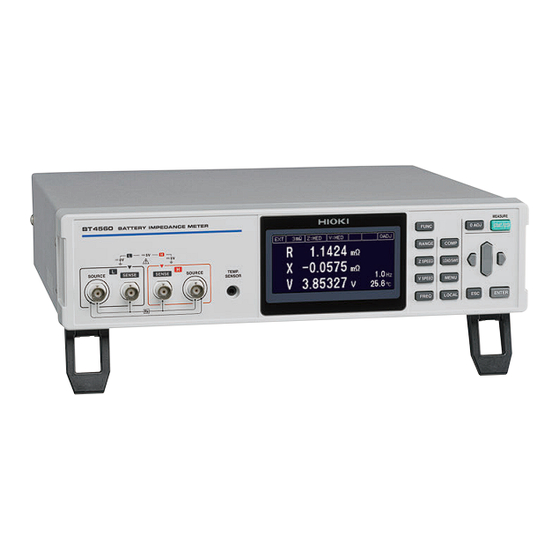
BT4560
BT4560-50
BATTERY IMPEDANCE METER
Read carefully before use.
Keep for future reference.
Safety Information
Names and Functions of Parts
Basic Measurement
May 2024 Revised edition 4
BT4560A981-04
The latest edition of the instruction manual
p.3
p.14
p.23
HIOKI BT4560A981-04
Instruction Manual
Troubleshooting
Error display and remedy
p.125
p.129
EN
[600441624]
Advertisement
Table of Contents

Subscribe to Our Youtube Channel
Related Manuals for Hioki BT4560-50


Summary of Contents for Hioki BT4560-50
- Page 1 BT4560 BT4560-50 Instruction Manual BATTERY IMPEDANCE METER The latest edition of the instruction manual Read carefully before use. Keep for future reference. Safety Information Troubleshooting p.125 Names and Functions of Parts p.14 Error display and remedy p.129 ...
-
Page 2: Table Of Contents
Checking the Measurement Sound ..........57 Results ..........32 Checking the Judgment Result ..58 „ Detecting the measurement abnormality (p. 129) ............32 „ Temperature measurement indication ..34 „ Overrange indication ........34 Basic Measurement Examples ..35 BT4560A981-04 HIOKI BT4560A981-04... - Page 3 Saving and Loading) „ Specifications ..........97 Connecting and Setting Method ... 99 Saving the Setting Conditions „ Selecting an interface (BT4560-50 only) ..99 (Panel Saving Function) ....60 „ Using the USB interface ......100 Reading the Setting Conditions „ Using the RS-232C cable ......101 (Panel Loading Function) ....
- Page 4 Appx. 10 Precautions When Measuring the Battery ...A15 Appx. 11 Calibrating the Instrument ..A18 Appx. 12 Rack Mounting .......A20 Appx. 13 Dimensional Diagram ....A22 Appx. 14 Creating Cole-Cole Plots Using PC Application Softwares ........A24 Appx. 15 License Information ....A25 Index Index1 HIOKI BT4560A981-04...
- Page 5 Contents HIOKI BT4560A981-04...
-
Page 6: Introduction
When you receive the instrument, inspect it carefully to ensure that no damage occurred during shipping. In particular, check the accessories, panel switches, and connectors. If damage is evident, or if it fails to operate according to the specifications, contact your authorized Hioki distributor or reseller. Confirm that these contents are provided. BT4560, BT4560-50... - Page 7 Verifying Package Contents Options (p. A12) The options listed below are available for the instrument. To order an option, please contact yourauthorized Hioki distributor or reseller. Options are subject to change. Please check Hioki’s website for the latestinformation. L2002 Clip Type Probe...
-
Page 8: Safety Information
Indicates prohibited actions. Indicates the action which must be performed. Additional information is presented below. Setting items and names on the screen are indicated in brackets Bold characters within the text indicate operating key labels. (Bold character) HIOKI BT4560A981-04... - Page 9 The value currently being measured and indicated on the measuring instrument. (Resolution) dgt. The smallest displayable unit on a digital measuring instrument, i.e., the input value that causes the digital display to show a “1” as the least-significant digit. HIOKI BT4560A981-04...
- Page 10 When measuring the circuit from the service drop to the service entrance, and to the power meter and primary overcurrent protection device (distribution panel). Distribution Panel Service Entrance Internal Wiring Service Drop CAT II CAT IV CAT III Outlet Power Meter Fixed Installation HIOKI BT4560A981-04...
-
Page 11: Operating Precautions
• Before using the instrument for the first time, verify that it operates normally to ensure that no damage occurred during storage or shipping. If you find any damage, contact your authorized Hioki distributor or reseller. Instrument installation Installing the instrument in inappropriate locations may cause a malfunction of instrument or may give rise to an accident. - Page 12 This instrument complies with EN 61326 Class A. This instrument may cause interference if used in residential areas. Such use must be avoided unless the user takes special measures to reduce electromagnetic emissions to prevent interference to the reception of radio and television broadcasts. HIOKI BT4560A981-04...
- Page 13 • To avoid electrical shock, do not exceed the every rating shown on either the instrument or each measurement probe, whichever is worse. WARNING • To avoid injury or damage to the instrument, do not attempt to measure AC voltage, or DC voltage exceeding 5 V DC. HIOKI BT4560A981-04...
- Page 14 • Be careful to avoid exceeding the ratings of connectors . • During operation, a wire becoming dislocated and contacting another conductive object can be serious hazard. Use screws to secure RS-232C. HIOKI BT4560A981-04...
- Page 15 • Be careful to avoid exceeding the ratings of the signal of the EXT.I/O terminals. (p. 119) During operation, a wire becoming dislocated and contacting another conductive object can be serious hazard. Use screws to secure the external connectors. HIOKI BT4560A981-04...
- Page 16 • Keep discs inside a protective case and do not expose to direct sunlight, high temperature, or high humidity. • Hioki is not liable for any issues your computer system experiences in the course of using this disc. HIOKI BT4560A981-04...
- Page 17 Operating Precautions HIOKI BT4560A981-04...
-
Page 18: Overview
* The Cole-Cole plot is a plot of the frequency characteristics of battery impedance in which the horizontal axis represents the real part of impedance and the vertical axis represents the imaginary part of impedance. This plot is used to evaluate the internal resistance of the battery. HIOKI BT4560A981-04... -
Page 19: Names And Functions Of Parts
Operating keys (p. 16) (SOURCE-L) Temperature sensor terminal Display Connects the Z2005 Monochrome graphic LCD temperature sensor. Rear MAC address(BT4560-50 only) Power inlet EXT.I/O terminal Indicates the MAC address. Connects the power Connects to an cord (accessory). external controller. USB interface... - Page 20 Names and Functions of Parts Bottom panel Stands Vents Side Raising/closing the stand CAUTION Do not apply heavy downward pressure with the stand extended. The stand could be damaged. HIOKI BT4560A981-04...
- Page 21 Releases the remote state and enables key operation. Performs the zero adjustment. Starts and stops the measurement. • Moves setting items and digits. • Changes numerical values. • Cancels the settings being set. • Erases a display message. Confirms the setting. HIOKI BT4560A981-04...
-
Page 22: Screen Configuration And Operation
Comparator setting screen measurement screen. When [EXIT] is selected, display returns to the Panel load/panel save screen measurement screen. When [EXIT] is selected, display returns to the Menu settings screen measurement screen. Zero adjustment setting screen HIOKI BT4560A981-04... -
Page 23: Measurement Flow
Perform zero adjustment (p. 28). Starting the measurement Connect the measurement probe to the object being measured. (For EXT trigger, start the measurement by pressing the START/STOP key.) Check the measurement values. Ending Turn Power Off (p. 21). HIOKI BT4560A981-04... -
Page 24: Preparation
(rear) of the instrument is OFF ( ). Check that the power voltage is in the range indicated on the rear, and then connect the power cord to the power inlet. Connect the plug of the power cord into an outlet. HIOKI BT4560A981-04... -
Page 25: Connecting The Measurement Probe And Temperature Sensor (Optional)
BNC connector into the instrument connector. Connector guide of the instrument’s current input terminal BNC connector groove of measurement probe Connect the temperature sensor to the instrument HIOKI BT4560A981-04... -
Page 26: Turning The Power On Or Off
2.4 Inspection Before Use Before using the instrument, verify that it operates normally to ensure that no damage occurred during storage or shipping. If you find any damage, contact your authorized Hioki distributor or reseller. Verifying the instrument and the peripheral devices... - Page 27 Inspection Before Use HIOKI BT4560A981-04...
-
Page 28: Basic Measurement
Phase angle θ , V, T measurement value Voltage measurement value Temperature Resistance measurement value Reactance R, X, T measurement value Temperature Impedance measurement value Phase angle θ measurement value Temperature Voltage measurement value V, T Temperature HIOKI BT4560A981-04... -
Page 29: Selecting The Measurement Range
Use the measurement range of impedance when the impedance measurement value exceeds the present range or when changing the measurement accuracy. When the functions (V, T) are selected, setting cannot be performed. By pressing (RANGE) the measurement ranges are switched. Ω Ω 100 m Ω 10 m Measurement ranges switches. HIOKI BT4560A981-04... -
Page 30: Setting The Measurement Speed
Measurement speed switches. Setting Items Contents V:FAST When the high speed measurement is performed, set this item. V:MED When the normal speed measurement is performed, set this item. V:SLOW When the high accurate measurement is performed, set this item. HIOKI BT4560A981-04... -
Page 31: Setting The Measurement Frequency
Setting the measurement frequency. BT4560 : 0.1 Hz to 1050 Hz BT4560-50 : 0.01 Hz to 1050 Hz Press (FREQ). (Measurement frequency setting screen appears.) The selected digit is displayed in reverse black and white, with a bar under the digit enabled to be set. -
Page 32: X84; When The Measurement Time Is Long (Display Of The Progress Bar)
The measurement is finished and the measurement value is displayed. During the detection of zero cross stop (When zero cross stop is ON) (p. 49) is displayed at the center of the progress bar. Progress bar ([Z] is displayed at the center.) HIOKI BT4560A981-04... -
Page 33: Performing The Zero Adjustment
• After performing the zero adjustment, even if the zero adjustment becomes ineffective, the zero adjustment will become effective when returning to the conditions that the zero adjustment was performed. • With the 0ADJ_SPOT of the EXT.I/O and 0ADJ_ALL terminals, performing can be done. HIOKI BT4560A981-04... - Page 34 Returns to the measurement screen without execution. Confirm Selection After the zero adjustment is normally performed, the screen will go back to the measurement screen. (When the zero adjustment is effective, 0 ADJ appears at the upper right on the measurement screen.) HIOKI BT4560A981-04...
- Page 35 1.500 m Voltage measurement -0.10000 V to 0.10000 V Disabling zero adjustment Select [OFF] on the zero adjustment screen. [OFF] (When is selected, zero adjustment will be disabled. To enable, perform zero adjustment again.) Confirm (or) Selection Cancel HIOKI BT4560A981-04...
-
Page 36: X84; Connection When Performing The Zero Adjustment
Connect SENSE-H and SENSE-L. Connect SOURCE-H and SOURCE-L. Connect the above lines at one point. SOURCE-L SENSE-L SENSE-H SOURCE-H Connection to the SOURCE shield Connection to the SOURCE shield Connect the above 2 and 3 at one point. HIOKI BT4560A981-04... -
Page 37: Checking The Measurement Results
• The resistance of the measuring object is remarkably large to the range (Example: when 1 k selected). • When wiring is wrongly connected to a battery. • When wiring is connected to a battery that is grounded. HIOKI BT4560A981-04... - Page 38 The return cable has a structure that short-circuits between the shield wire of the SOURCE-H and the shield wire of the SOURCE-L. (In the optional probe, the return cable short-circuits between the shield wire of the SOURCE-H and the shield wire of the SOURCE-L.) HIOKI BT4560A981-04...
-
Page 39: X84; Temperature Measurement Indication
Each parameter over-indicates due to causes listed below. Parameters Over indication Cause The measurement value of Z exceeds the indication range of the OverRange present range. θ +Over°C The measurement value is greater than 60.0°C. -Under°C The measurement value is smaller than -10.0°C. HIOKI BT4560A981-04... -
Page 40: Basic Measurement Examples
Impedance measurement frequency 1 Hz Zero adjustment Set the measurement functions (R, X, V, T). (p. 23) Ω Set the measurement range at 100 m . (p. 24) Set the measurement speed of impedance measurement (Z) at [FAST]. (p. 25) HIOKI BT4560A981-04... - Page 41 Set the speed of the voltage measurement (V) at [SLOW]. (p. 25) Set the measurement frequency of impedance at 1 Hz. (p. 26) Connect the zero adjustment connection and then perform the all zero adjustment. (p. 28) Connect the battery cell. Battery cell Press START/STOP to measure. HIOKI BT4560A981-04...
- Page 42 Basic Measurement Examples Check the measurement results. HIOKI BT4560A981-04...
- Page 43 Basic Measurement Examples HIOKI BT4560A981-04...
-
Page 44: Customization Of Measurement Conditions
Trigger signals are automatically generated internally to perform the automatic- Internal trigger measurement. Setting the trigger Press (MENU). (The setting screen appears.) Select [MEAS] tab. Selection Select [EXT] (external trigger) or [INT] (internal trigger). Confirm Selection (or) Cancel HIOKI BT4560A981-04... -
Page 45: X84; Inputting The External Trigger
Settings based on waveform (WAVE) Alternating Current response of the battery Set the delay with the frequency of the Alternating Current signal. (This is an example for delay of frequency 4.) Sampling Sample delay Application of Alternating Current HIOKI BT4560A981-04... - Page 46 The slope of Alternating Current response is monitored and sampling is started when the slope of deviation (∆VOLT) drops below the set value. Press (MENU). (The setting screen appears.) Select [MEAS] tab. Selection Select [WAVE] or [∆VOLT]. Confirm (or) Selection Cancel HIOKI BT4560A981-04...
- Page 47 Cancel Changing the numerical value (up and down) When selecting [∆VOLT], set the voltage. (00.001 mV to 10.000 mV) Confirm Setting (or) Move to the next digit (left or right) Cancel Changing the numerical value (up and down) HIOKI BT4560A981-04...
-
Page 48: Maintaining Voltage Measurement Accuracy (Self-Calibration Function)
(Perform it under the TRIG waiting condition. When the signal is input, perform it after the measurement.) Press (MENU). (The setting screen appears.) [MEAS] Select tab. Selection Select [AUTO] or [MANUAL]. Confirm Selection (or) Move to the next digit (left or right) Cancel Changing the numerical value (up and down) HIOKI BT4560A981-04... -
Page 49: Stabilizing The Measurement Values (Average Function)
(MENU). (The setting screen appears.) [MEAS] Select tab. Selection Sets the number of measured values to be used for averaging. (1 to 99) Confirm Selection (or) Move to the next digit (left or right) Cancel Changing the numerical value (up and down) HIOKI BT4560A981-04... -
Page 50: Compensating The Potential Slope Due To Electric Discharge (Slope Correction Function)
“Starting the Measurement After the Response of the Measuring Object is Stable (Sample Delay Function)” (p. 40) is used, and wait to measure until the measuring object’s response time becomes stable. Proper compensation cannot be performed for drifts that are not linear. Compensation is enabled for linear drift. HIOKI BT4560A981-04... - Page 51 Compensating the Potential Slope Due to Electric Discharge (Slope Correction Function) Press (MENU). (Settings screen is displayed.) [MEAS] Select tab. Selection Select [ON] or [OFF]. Confirm (or) Selection Cancel HIOKI BT4560A981-04...
-
Page 52: Preventing The Overcharge Due To Measurement Signal (Voltage Limit Function)
The battery may be overcharged, if the measurement is repeated at a high voltage value setting. Press (MENU). (Settings screen is displayed.) Select [MEAS] tab. Selection [ON] or [OFF]. Select Confirm (or) Selection Cancel HIOKI BT4560A981-04... - Page 53 Preventing the Overcharge due to Measurement Signal (Voltage Limit Function) When selecting [ON], set the voltage. (0.01 V to 5.00 V) Confirm Selection (or) Move to the next digit (left or right) Cancel Changing the numerical value (up and down) HIOKI BT4560A981-04...
-
Page 54: Prevents Charging And
Measurement cannot be interrupted during the detection of zero cross stop. The charging and discharging of the battery is prevented by stopping the measurement current at zero cross. Charging Discharging Press (MENU). (Settings screen is displayed.) Select [MEAS] tab. Selection HIOKI BT4560A981-04... - Page 55 Prevents Charging and Discharging due to the Measurement Signal (Measurement Signal Zero Cross Stop Function) Select [ON] or [OFF]. Confirm (or) Selection Cancel HIOKI BT4560A981-04...
-
Page 56: Judging Measurement Results (Comparator Function)
Even if wiring is connected in reversed polarity, judgment can be performed correctly. (Example: If the upper limit 3 V, Lower limit is -1 V, and the measurement value is -2 V) Measurement value Absolute value Lower limit value Upper limit value Judgment -1 V -2 V (IN judgment) HIOKI BT4560A981-04... -
Page 57: Turning The Comparator Function On And Off
Turning the Comparator Function ON and OFF 5.1 Turning the Comparator Function ON and OFF Press (COMP). (The setting screen appears.) Select [SYST] tab. Selection Select [ON] or [OFF]. Confirm Selection (or) Cancel HIOKI BT4560A981-04... -
Page 58: Setting The Upper And Lower Limit Value
The following describes the setting method, taking R, X, V as the examples. Setting examples Ω Ω Upper limit value: 7.5 m Lower limit value: No judgment Upper limit value: Lower limit value: Press (COMP). (The setting screen appears.) Select [COMP] tab. Selection Select parameter [R]. Confirm Setting (or) Cancel HIOKI BT4560A981-04... - Page 59 Set the upper limit value of at 5.00000 V, and the lower limit value at 4.00000 V. Move to the next digit (left or right) Confirm Changing the numerical value (up and down) (or) Upper limit value Lower limit value Cancel HIOKI BT4560A981-04...
- Page 60 -180.000° to +180.000° -5.10000 V to +5.10000 V Common in all ranges IMPORTANT When the value of Hi is set smaller than the value of Lo, the value of Hi set is corrected to the value of Lo. HIOKI BT4560A981-04...
-
Page 61: Voltage Is Judged With The Absolute Value
Sets the upper and lower limit values for [V]. (p. 53) Move to the next digit (left or right) Confirm Changing the numerical value (up and down) (or) Cancel Upper limit value Lower limit value Select [SYST] tab. Selection Select [ON] or [OFF]. Confirm Setting (or) Cancel HIOKI BT4560A981-04... -
Page 62: Checking The Judgment With Sound
—: No buzzer sound, (long sound): Long buzzer sound, (three short sounds): Three short buzzer sounds. Press (COMP). (The setting screen appears.) Select [SYST] tab. Selection Select the buzzer sound from among [OFF], [IN], [Hi • Lo], [ALL]. Confirm Selection (or) Cancel HIOKI BT4560A981-04... -
Page 63: Checking The Judgment Result
Output of EXT. I/O Judgment Measurement result result PASS FAIL Hi Set value < Measured value Lo Set value ≤ Measured value ≤ Hi Set value Measured value < Lo Set value OverRange Measurement Error judgment During interruption of measurement judgment HIOKI BT4560A981-04... -
Page 64: Saving And Reading Measurement Conditions (Panel Saving And Loading)
• Zero adjustment data • Sample delay setting • Comparator setting contents • Average • Slope correction setting • Voltage limit • Self -Calibration settings • Measurement signal zero • Trigger source cross stop function Numbers of panel HIOKI BT4560A981-04... -
Page 65: Saving The Setting Conditions (Panel Saving Function)
Select the number of the panel that will be saved. Confirm Selection (or) Cancel Select [SAVE]. Confirm Selection (or) Cancel (When selecting the number of the panel that has been saved, the confirmation window will appear.) Overwriting CANCEL: Cancel Confirm Selection HIOKI BT4560A981-04... - Page 66 Saving the Setting Conditions (Panel Saving Function) When [+5] is selected, the next 5 panel numbers are displayed. When [-5] is selected, the previous 5 panel numbers are displayed. HIOKI BT4560A981-04...
-
Page 67: Reading The Setting Conditions (Panel Loading Function)
Select the number of the panel that will be read. Confirm Selection (or) Cancel Select [LOAD]. Confirm Selection (or) Cancel When [+5] is selected, the next 5 panel numbers are displayed. When [-5] is selected, the previous 5 panel numbers are displayed. HIOKI BT4560A981-04... -
Page 68: Deleting The Contents Of The Panel
6.3 Deleting the Contents of the Panel Deletes saved measurement conditions. Press (LOAD/SAVE). (Panel screen is displayed.) Select a panel number to be deleted. Confirm Selection (or) Cancel Select [CLEAR]. Confirm Selection (or) Cancel Opens confirmation window. Clear CANCEL: Cancel Confirm Selection HIOKI BT4560A981-04... - Page 69 Deleting the Contents of the Panel HIOKI BT4560A981-04...
-
Page 70: System Setting
Ineffective Makes the key operation except for (START/STOP) ineffective. Ineffective Press (MENU). (The setting screen appears.) Select [SYST] tab. Selection Select [ON]. Confirm Selection (or) Cancel [LOCK] appears on the measurement screen, and the key operation becomes ineffective. HIOKI BT4560A981-04... - Page 71 Making the Key Operation Effective or Ineffective Effective Press (LOCAL) and hold for at least 5 seconds. [LOCK] disappears on the measurement screen, and the key operation becomes effective. HIOKI BT4560A981-04...
-
Page 72: Setting The Sound Of The Key Operation Effective Or Ineffective
Make the sound of the key operation effective or ineffective. Press (MENU). (The setting screen appears.) Select [SYST] tab. Selection Select [ON] or [OFF]. : The operation sound is beeped. : The operation sound is not beeped. Confirm Selection (or) Cancel HIOKI BT4560A981-04... -
Page 73: Adjusting The Contrast Of The Screen
: Increases the contrast. : Decreases the contrast. Setting range : 0% to 100%, steps of 5% (default setting: 50%) Confirm Setting (or) Move to the next digit (left or right) Cancel Changing the numerical value (up and down) HIOKI BT4560A981-04... -
Page 74: Adjusting The Backlight
: Raise the backlight brightness. : Drop the backlight brightness. Setting range : 10% to 100%, steps of 5% (default setting: 80%) Confirm Setting (or) Move to the next digit (left or right) Cancel Changing the numerical value (up and down) HIOKI BT4560A981-04... -
Page 75: System Testing
Test I/O devices. (Commands and queries due to communication could not be performed during I/O testing.) Output signal: Signals can be operated. Signal ON / OFF ON: Reverse display OFF: Normal display Selection Cancel Input signal: Signal state is displayed. HIOKI BT4560A981-04... - Page 76 Selection Select [KEY TEST]. Selection To Testing screen Press the keys of the instrument to test the keys. (Check that all the key names on the screen are reversed.) The screen returns to the key test screen. Return HIOKI BT4560A981-04...
- Page 77 To Testing screen The explanation screen for test is displayed. Execute Return Press ENTER, and confirm that all screen indicators lights up and off repeatedly. (The display below shows that all screen indicators are lit off.) Execute Return HIOKI BT4560A981-04...
- Page 78 This test can check that the program data of the instrument is normal. Press (MENU). (The setting screen appears.) Select [TEST] tab. Selection Select [ROM TEST]. Selection Execute Test the ROM. The screen returns to the ROM testing screen. Return HIOKI BT4560A981-04...
- Page 79 Response of communications command and queries can be displayed on the screen. Press (MENU). (Settings screen is displayed.) Select [TEST] tab. Selection Select [COMMAND MONITOR]. Selection Execute Confirm the contents of the communication commands. Press (LOCAL). (Key operation is enabled.) (or) Return HIOKI BT4560A981-04...
-
Page 80: Confirm Instrument Information
(MENU). (Settings screen is displayed.) Select [INFO] tab. (The software version and serial number will be displayed.) Selection Software version Serial number The 9-digit serial number indicates the year (first two digits) and the month of manufacture (next two digits). HIOKI BT4560A981-04... -
Page 81: Initializing (Reset)
Resetting the LAN settings to the factory default. For details of resetting items, refer to “Initial setting table” (p. 78). Press (MENU). (The setting screen appears.) [SYST] Select tab. Selection Select the reset method. Confirm (or) Selection Cancel HIOKI BT4560A981-04... - Page 82 CANCEL : Returns to the measurement screen without execution. When NORMAL is selected Confirm Selection When SYSTEM is selected Confirm Selection When LAN is selected Confirm Selection The display returns to the measurement screen after the reset process is completed. HIOKI BT4560A981-04...
-
Page 83: X84; Initial Setting Table
V Corrected value 0.0V Self -Calibration AUTO Delay mode WAVE Sample Delay time 1.0 wave delay Acceptable range of 10 μV deviation Average Measurement signal zero cross stop Slope Correction ON/OFF Voltage limit Acceptable range 4.2 V HIOKI BT4560A981-04... - Page 84 Communication speed 9,600 bps Header Status byte register − − Event register Enable register Type IP address 192.168.1.1 Interface (only Subnet mask 255.255.0.0 − − − − BT4560- Default gateway (0.0.0.0) Port number : Applicable, −: Not applicable HIOKI BT4560A981-04...
- Page 85 Initializing (Reset) HIOKI BT4560A981-04...
-
Page 86: External Control (Ext.i/O)
Signal input/output Check the specifications of the controller’s input/output. Set the NPN/PNP switches of the instrument (p. 82). Connect between the EXT.I/O connector of the instrument and the controller (p. 82). Configure the instrument settings. HIOKI BT4560A981-04... -
Page 87: External Input/Output Terminals And Signals
Arranging the usage connector and the signals Usage connector • 37-pin D-sub socket contact with #4-40 inch screws Mating Connectors • DC-37P-ULR (solder type) EXT I / O • DCSP-JB37PR (compression contact type) Manufactured by Japan Aviation Electronics Industry, Ltd. Other comparable products HIOKI BT4560A981-04... - Page 88 (Don’t use) (Don’t use) FAIL Judgment result FAIL Level IMPORTANT The connector shell is conductively connected to the metal instrument chassis and the protective earth pin of the power inlet. Be aware that it is not isolated from ground. HIOKI BT4560A981-04...
-
Page 89: X84; Functions Of Each Signal
(TRIG) signal to ON, the panel loading is not performed. • In the case of setting to the external trigger, the measurement is performed once after the completion of the loading. • In the case of setting to the internal trigger, panel loading will not be performed. HIOKI BT4560A981-04... - Page 90 • When it is not necessary to switch the measurement conditions, fix all of LOAD0 to LOAD6 at ON or OFF. • To avoid misjudgment, check with both the PASS and FAIL signals for the judgment to the comparator. HIOKI BT4560A981-04...
-
Page 91: Timing Chart
Self- V sam- Z sampling Measurement V calcu- Switching mea- Z calculation Calibration pling lation surement circuit processing Measurement current stop Stop Application INDEX Judgment result Judgment results: HI, IN, LO, PASS, FAIL, ERR HIOKI BT4560A981-04... - Page 92 • The output of the judgment result is determined before the EOM signal becomes ON. When the response of the controller input circuit is slow, a wait is required from when the EOM signal ON is detected until the judgment results are read. HIOKI BT4560A981-04...
- Page 93 (1÷f)×N+T+0.016* and p. 110. time Sampling control time differs due to the frequency. T=0.088÷ f (f: 0.1 Hz to 66 Hz) T=0.36÷ f (f: 67 Hz to 250 Hz) T=1.5÷ f (f: 260 Hz to 1050 Hz) HIOKI BT4560A981-04...
-
Page 94: X84; Timing Of The Zero Adjustment
The self-calibration is performed to maintain the accuracy of the voltage calibration. In the case θ of the measurement functions (R, X, T) and (Z, , T) where the voltage measurement is not performed, the self-calibration is not performed. (Even if the CAL signal is input, the self-calibration is not performed.) HIOKI BT4560A981-04... - Page 95 When the TRIG signal is input during the self-calibration TRIG 210 ms Measurement During mea- During mea- Self-Calibration processing surement surement When the CAL signal is input during the measurement TRIG 210 ms Measurement During measurement Self-Calibration processing HIOKI BT4560A981-04...
-
Page 96: X84; Timing Of The Panel Loading
Turn On the power supply Power supply Status Measurement screen starting screen INDEX Judgment result TRIG Judgment results: HI, IN, LO, PASS, FAIL, ERR The above chart indicates the operation when the trigger source is set to the EXT. HIOKI BT4560A981-04... -
Page 97: X84; Taking-In Flow With The External Trigger
Starting the TRIG measurement Waiting for judgment result OFF (In the case of During level detection, measurement waiting for 0.5 ms.) Completion of measurement End of measurement reception HI, IN, LO, PASS, FAIL, ERR Judgment result acquisition HIOKI BT4560A981-04... -
Page 98: Internal Circuitry
Ω START (TRIG) Output 0ADJ_ALL Common EXT.I/O MODE Internally isolated selector power supply PLC, others Ω Input Zener voltage 30 V RorZ_HI ISO_COM ISO_COM Common Internally isolated common 30 V max (This is isolated to the protective ground.) HIOKI BT4560A981-04... -
Page 99: X84; Electrical Specifications
-5.0 V±10% supply Maximum output 100 mA current External power input None Insulation Floating from the protective grounding potential and the measurement circuit Insulation rating Voltage to ground 50 V DC, 33 V AC rms, less than 46.7 Vpeak HIOKI BT4560A981-04... -
Page 100: X84; Examples Of Connection
ISO_COM Negative logic output ISO_COM wired-OR BT4560 BT4560 Output Input Output Input 50 mA max 50 mA max ISO_COM Common ISO_COM Common Connection to PLC input (minus common input) Connection to PLC input (plus common input) HIOKI BT4560A981-04... -
Page 101: Checking The External Control
Testing the inputs/outputs (EXT.I/O testing functions) The output signal can be switched ON and OFF manually. In addition, the condition of the input signal can be monitored on the screen. For details, refer to “I/O TEST” (p. 70). HIOKI BT4560A981-04... -
Page 102: Communication (Rs-232C, Usb, Lan)
• Controlling the instrument using commands and acquiring data. • Using application software. The command table and the application software can be downloaded from the attached CD or our website (http://www.hioki.com/). Only the BT4560-50 can communicate on a LAN. Specifications Connector Series B receptacle Electrical Specifications USB2.0 (pseudo COM port) - Page 103 Features of Interface LAN(BT4560‑50 only) Applicable standard IEEE802.3 Transmission method 10BASE-T / 100BASE-TX automatic recognition Half/Full Duplex, Auto MDI-X Protocol TCP/IP Connector RJ-45 Communication description Setting and measured value acquisition by using communications commands HIOKI BT4560A981-04...
-
Page 104: Connecting And Setting Method
BT4560 via both the USB and RS-232C ports, only USB communications are available. As for BT4560-50, the communications method selected under the procedure described in the section “Selecting an interface (BT4560-50 only)” (p. 99) is available. -
Page 105: X84; Using The Usb Interface
If the driver has already been installed, for example, due to using products from other manufacturers, the following procedure is not necessary. The USB driver can be downloaded from the attached CD or our website (http://www.hioki.com/). Installation procedure Perform the installation before connecting between the instrument and the computer with the USB cable. If they already connected, unplug the USB cable. -
Page 106: X84; Using The Rs-232C Cable
Use crossing cable of D-sub9 Pin Female - D-sub9 Pin Female. Cross connection D-sub 9 Pin Female D-sub 9 Pin Female Computer/ Instrument side AT compatible computer Pin No. Pin No. Recommended cable: Model 9637 RS-232C Cable (1.8 m) manufactured by HIOKI HIOKI BT4560A981-04... -
Page 107: X84; Setting The Transmission Speed (Common For Usb, Rs-232C)
• Parity check: Not provided • Flow control: Not provided IMPORTANT The fast transmission speed (baud rate) may not be used due to a large error caused by some computers. In that case, use with lower transmission speed. HIOKI BT4560A981-04... -
Page 108: X84; Using The Lan Interface (Bt4560-50 Only)
LANs. Such signal wiring is susceptible to inducedlighting, which can cause damage to the instrument. Recommended cable: Model 9642 LAN cable (optional) Green LED Lit: Linking Blink: Communicating Orange LED Off: 10BASE-T Lit: 100BASE-TX Instrument LAN connector PC and hub HIOKI BT4560A981-04... -
Page 109: X84; Setting Lan Communications (Bt4560- 50 Only)
Set sequential IP addresses as shown below. 192.168.1.100 First instrument: 192.168.1.1 (instrument’s default setting) Second instrument: 192.168.1.2 Third instrument: 192.168.1.3 ↓ Subnet mask: 255.255.0.0 (instrument’s default setting) Gateway: OFF (instrument’s default setting) Communication command port number: 23 (instrument’s default setting) HIOKI BT4560A981-04... - Page 110 If you don’t know the IP address, you can change the setting as follows. Enter [http://hioki-] in the address bar, followed by the last six digits of the instrument’s MAC address. You can find the MAC address on the sticker on the rear of the instrument.
- Page 111 Select (MENU) > [SYST] tab > [RESET] and select [LAN] to reset the settings. The following settings will be reset to their default values: IP address: 192.168.1.1 Subnet mask: 255.255.0.0 Default gateway: OFF (0.0.0.0) Communications command port: 23 HIOKI BT4560A981-04...
-
Page 112: X84; Outputting Measured Values After Measurement Completes
Press (MENU). (The settings screen will be displayed.) Select [SYST] tab. Selection [DATA OUT], set to [ON] or [OFF], and press the ENTER Select key to accept the setting. Confirm Selection (or) Cancel HIOKI BT4560A981-04... -
Page 113: Controlling The Communication And Acquiring The Data
Press (LOCAL). Then, the remote status is released and the key operation is possible. When the instrument indicates the setting screen, if it becomes the remote status, the screen automatically moves to the measurement screen. HIOKI BT4560A981-04... -
Page 114: Specifications
Resolution 0.1 µ 0.1 µ 1 µ Frequency range BT4560 0.10 Hz to 1050 Hz BT4560-50 0.01 Hz to 1050 Hz Frequency setting 0.01 Hz to 0.99 Hz 0.01 Hz step resolution 1.0 Hz to 9.9 Hz 0.1 Hz step... - Page 115 Overrange display OVER VOLTAGE Temperature measurement Measurement terminal Four-terminal earphone jack φ3.5 mm structure Measurement items Temperature (Parameter indication: T) Display range -10.0°C to 60.0°C Resolution 0.1°C Sampling time 2.3 s Overrange indication +Over°C, -Under°C Indication when --.-°C unconnected HIOKI BT4560A981-04...
- Page 116 T=0.36 ÷ f (f : 67 Hz to 250 Hz) T=1.5 ÷ f (f : 260 Hz to 1050 Hz) Measurement signal (1÷f) or less (f: Measurement frequency) (Unit is “s”) zero cross detection Z calculation time 70 ms HIOKI BT4560A981-04...
-
Page 117: Additional Function
Frequency setting Function overview Setting the measurement frequency of impedance measurement. Function setting BT4560 0.10 Hz to 1050 Hz BT4560-50 0.01 Hz to 1050 Hz Setting backup Measurement speed setting Function overview Setting impedance measurement, Setting measurement speed of voltage measurement. - Page 118 Voltage drift of the measuring object VOLTAGE DRIFT measurement Over-voltage input error When voltage is measured OVER VOLTAGE Voltage limit error When voltage is measured OVER V LIMIT After impedance RETURN CABLE Return cable unconnected error measurement ERROR HIOKI BT4560A981-04...
- Page 119 Will not Measurement Error judge During interruption of Will not measurement judge Setting backup Zero adjustment Function overview Removing the residual components caused from offset and the measurement environment. Adaptive Impedance measurement, voltage measurement measurement Function setting ON/OFF HIOKI BT4560A981-04...
- Page 120 Averaging specified times of impedance measurement values and then output. Function setting 1 to 99 times Averaging method Simple average ∑ avg( ) − Setting backup Slope correction of impedance measurements Function overview Compensating the slope of AC signal when the impedance measurement is performed. (p. 45) HIOKI BT4560A981-04...
- Page 121 Function overview Setting the communication interface. Function setting BT4560 RS-232C/USB (automatic recognition that USB is taken priority. Both cannot be use simultaneously.) BT4560-50 RS-232C/USB/LAN (Manual selection) Transmission speed setting 9,600 bps/19,200 bps/38,400 bps (Transmission delimiter is fixed with CR+LF.) Setting backup...
- Page 122 Check that the output signal is output normally from the EXT I/O, and the input signal is read normally. Communication monitor The command and the response for the query is displayed on the screen. Error display “Error display and remedy” (p. 129) HIOKI BT4560A981-04...
-
Page 123: User Interface
Interface types BT4560 RS-232C/USB (Both RS-232C and USB cannot be controlled simultaneously. When both the USB and the RS-232C communication are connected, the USB connection is effective.) BT4560-50 RS-232C/USB/LAN (Manual selection) RS-232C Communication Remote control, measured value output contents Transmission method... - Page 124 External Interface LAN (BT4560-50) Settings can be changed by accessing the instrument using a web browser. Applicable standard IEEE802.3 Transmission method 10BASE-T/100BASE-TX automatic recognition Half/Full Duplex, Auto MDI-X Protocol TCP/IP Connector RJ-45 Communication Setting and measured value acquisition by using communications commands...
-
Page 125: Accuracy
15 dgt. 15 dgt. Temperature R: ±R Accuracy × 0.1/°C coefficient X: ±X Accuracy × 0.1/°C Z: ±Z Accuracy × 0.1/°C θ θ : ± Accuracy × 0.1/°C Applied in the range (0°C to 18°C, 28°C to 40°C) HIOKI BT4560A981-04... - Page 126 -5.10000 V to 5.10000 V Resolution 10 µV FAST ±0.0035% rdg.±5 dgt. Voltage accuracy ±0.0035% rdg.±5 dgt. SLOW ±0.0035% rdg.±5 dgt. Temperature ±0.0005% rdg.±1 dgt./°C coefficient (Applied in the ranges of 0°C to 18°C, and 28°C to 40°C) HIOKI BT4560A981-04...
- Page 127 ) × 0.1/°C × 3°C Ω Ω = ±0.00585 m (Rounded down to the displayed digit ±0.0058 m Voltage measurement accuracy <Measurement condition 1> Measurement range: arbitrary, Measurement speed: arbitrary, Frequency: arbitrary, Measuring object: R=arbitrary, X=arbitrary, V=3.6 V HIOKI BT4560A981-04...
-
Page 128: General Specifications
Anticipated transient overvoltage 2500 V Rated supply frequency 50 Hz/60 Hz Maximum rated power 80 VA Normal power 37 W(BT4560-50) Ω consumption Conditions: Supply voltage 264 V/60 Hz, 3 m range (measurement current 1.5 A rms), (reference value) frequency 1050 Hz Maximum input voltage ±5 V (Between H terminal and L terminal) -
Page 129: X84; Standards
General Specifications Weight BT4560 Approx. 3.7 kg (130.5 oz.) BT4560-50 Approx. 3.8 kg (134.0 oz.) Standards Safety EN61010 EN61326 Class A Effect of radiated radio-frequency For a frequency range of 80 MHz to 1 GHz, the electromagnetic field accuracy is specified in an electromagnetic field of 10 V/m. -
Page 130: Maintenance And Service
• When sending the instrument for repair, pack carefully to prevent damage in transit. Include cushioning material so the instrument cannot move within the package. Be sure to include details of the problem. Hioki cannot be responsible for damage that occurs during shipment. - Page 131 → Reduce the range of the measurement − capacity current. is small. Temperature sensor is not correctly is not Temperature connected. inserted − sensor → Insert the temperature sensor all the all the way in. way in. HIOKI BT4560A981-04...
- Page 132 The EOM signal will be ON once the EOM signal logic p. 85 measurement is completed. HI, IN, and LO Judgment results are signals are not not displayed on the Confirm Q&A in 1-3. p. 125 output. instrument screen. HIOKI BT4560A981-04...
- Page 133 Sending → “1” reception. On the An answer to The program is not correct. response communi- the query is not → The instrument is returning the query. − present. cation returned. Check the receiving part of the program. monitor HIOKI BT4560A981-04...
-
Page 134: X84; Error Display And Remedy
Troubleshooting Error display and remedy When an error is displayed on the LCD screen, repair is necessary. Please contact your authorized Hioki distributor or reseller. Display Error No. Cause Countermeasures The measurement value OverRange None exceeds the impedance Set the correct range. - Page 135 Request repairs. OVER CURRENT The device fails. ERR:96 The internal circuit is broken. ERROR Request repairs. The built in battery of the Please contact your authorized VREF B ERROR ERR:97 instrument has to be replaced. Hioki distributor or reseller. HIOKI BT4560A981-04...
-
Page 136: Inspection, Repair And Cleaning
The calibration period varies with the conditions and environment of use. It is recommended to determine a calibration period based on those factors and to have the instrument regularly calibrated by Hioki. Please contact your Hioki distributor to have your instrument periodically calibrated. -
Page 137: Discarding The Instrument
Take care not to short the + and -. Doing so may cause sparks. Lithium battery CALIFORNIA, USA ONLY This product contains a CR Coin Lithium Battery which contains Perchlorate Material - special handling may apply. See https://dtsc.ca.gov/perchlorate/ HIOKI BT4560A981-04... -
Page 138: Appendix
θ = − Ω Impedance ( θ = − Phase angle (deg) Imaginary part Ω Resistance ( Ω Reactance ( θ = − θ = − Ω Absolute value of impedance ( Real part HIOKI BT4560A981-04... -
Page 139: Appx. 2 Four-Terminal Pair Method
The AC four-terminal method is suitable for a low resistance measurement because it is affected by the resistance of the wiring and the contact resistance. The magnetic field of the measuring current produces an induced electromotive force that affects the SENSE terminals. HIOKI BT4560A981-04... - Page 140 It is important that the shape of the return cable, which affects the magnetic field, is not changed. Shield Tip end: SOURCE-H SOURCE-H Tip end: SENSE-H SENSE-H Return cable Measuring object SENSE-L Tip end: SENSE-L SOURCE-L Tip end: SOURCE-L HIOKI BT4560A981-04...
-
Page 141: Your Own Measurement Probe
SOURCE-H SENSE-H Measuring object SENSE-L SOURCE-L • If you connect the cables together so as to measure the object being measured using the two-terminal connection, you will not be able to obtain the correct measurement values. Measuring object HIOKI BT4560A981-04... - Page 142 For details, refer to “Zero Adjustment” (p. A8). Set the following to the same conditions as those when measuring. • Loop area • Loop shape • Probe spacing • Wiring position (distance to the surrounding metal part of a device) HIOKI BT4560A981-04...
-
Page 143: Structure And Extension
Extension We can fill requests for probe extensions as a special order. Contact the distributor (store) from which you purchased the instrument or your nearest Hioki sales office. Observe the following precautions when extending the measurement probes by yourself. • Use a thicker lead wire and a minimum length that you can prepare and implement as the extension. -
Page 144: Measurement Value Due
Pin Type Probe L2003 Clip Type Probe L2002 Pin spacing: 2.5 mm Spacing: 6.3 mm terminal terminal terminal terminal Battery Battery Equipotential line Equipotential line Potential slope V (detected voltage): A>B Potential slope HIOKI BT4560A981-04... -
Page 145: Appx. 6 Influence Of The Eddy Current A8
SOURCE-H from flowing into the wiring of SENSE-H and SENSE-L. Consequently, the voltage between SENSE-H and SENSE-L can be maintained accurately at 0 V and zero adjustment can be performed. HIOKI BT4560A981-04... - Page 146 SOURCE-L, and then connecting the Hi-side and the Lo-side with one path, there is a voltage potential difference of I × R between SENSE-H and SENSE-L. Thus, the connection method does not create Short Ω conditions where a pseudo resistance of 0 is connected, and thus, does not perform the correct zero adjustment. HIOKI BT4560A981-04...
- Page 147 Short and SENSE-L Path where the → R → R → R measurement Short current I flows Voltage produced I × R between SENSE-H Short and SENSE-L As the connection method when Correct Incorrect performing the zero adjustment HIOKI BT4560A981-04...
- Page 148 SOURCE-H SOURCE-L Equivalent circuit Short Short Constant-current power supply Constant-current power supply Voltmeter Voltmeter Detailed equivalent SOURCE-H SENSE-H SENSE-L SOURCE-L SOURCE-H SENSE-H SENSE-L SOURCE-L circuit Short Short As the connection method when Correct Incorrect performing the zero adjustment HIOKI BT4560A981-04...
-
Page 149: Appx. 8 Measurement Probe (Option) A12
Adjust the position of the probes such that the return cable between the probes does not sag, and fix by pushing the return cable into the grooves of the probes. (The return cable is indicated black in the illustration.) Measuring object HIOKI BT4560A981-04... -
Page 150: Making The Switching Unit
When designing the patterns with two or more layers, the loop can be minimized by layering a pair of patterns over it. (Figure. Pattern Layout Examples of the Switching Unit (in the case of the substrate with the two or more layers)) HIOKI BT4560A981-04... - Page 151 Lap over between layers (a) First layer (b) Second layer Figure. Pattern layout examples (in the case of the substrate with two or more layers) Twist Figure. Wiring example of the switching unit (in the case of wiring the electrical wires) HIOKI BT4560A981-04...
-
Page 152: Measuring The Battery
If applying an input to the L terminal which provides the L terminal has a potential to the ground, the circuit may be broken. Do not connect equipment other than the instrument during measurement. There is a risk of circuit damage due to improper grounding of equipment. Refer to the following figure. HIOKI BT4560A981-04... - Page 153 Precautions When Measuring the Battery Cases that cannot be measured If the voltage exceeds 5 V H terminal BT4560 L terminal Imaginary grounding In case of measuring the cell that has been grounded H terminal BT4560 L terminal HIOKI BT4560A981-04...
- Page 154 When instruments to be grounded are internally grounded or when capacitance between groundings is large. Cases that can be measured If battery modules have not been connected H terminal BT4560 L terminal If both ends of the battery are cut off from the ground Virtual ground HIOKI BT4560A981-04...
-
Page 155: Appx. 11 Calibrating The Instrument
• For connection between this instrument and the standard resistor, refer to the figure shown below. Shield box Shield The instrument Ω SOURCE-H SENSE-H SENSE-L SOURCE-L Ω Figure. Calibrating 0 Shield box Shield The instrument Standard resistor SOURCE-H SENSE-H SENSE-L SOURCE-L Figure. Connecting to the standard resistor HIOKI BT4560A981-04... - Page 156 • Use the connection terminals of φ3.5 four-terminal structure (For the four-pole signal cable, refer to Figure illustrated below.) The instrument Standard resistor TEMP.SENSOR TEMP C1 TEMP P1 TEMP P2 TEMP C2 Figure. Connecting to the standard resistor TEMP C1 TEMP C2 TEMP P1 TEMP P2 Figure. Connection terminal’s structure HIOKI BT4560A981-04...
-
Page 157: Appx. 12 Rack Mounting
(Standard: M3 × 6 mm, sides: M4 × 6 mm, when installing rack mounting bracket: M4 × 10 mm) If screws are lost or damaged, contact your authorized Hioki distributor or reseller. Rack Mounting Plate (EIA) 2×C2... - Page 158 Rack Mounting Plate with the M4 × 10 screws. Spacers • When installing into the rack, reinforce the installation with a commercially available support stand. • Ensure that the vents on the sides, rear, and bottom are not blocked. HIOKI BT4560A981-04...
-
Page 159: Appx. 13 Dimensional Diagram
Dimensional Diagram Appx. 13 Dimensional Diagram 15 mm 75.2 mm 330 mm±1 mm 32 mm±0.2 mm 21.5 mm±0.2 mm HIOKI BT4560A981-04... - Page 160 Dimensional Diagram 21 mm±0.5 mm 287 mm±0.5 mm HIOKI BT4560A981-04...
-
Page 161: Using Pc Application Softwares
Equipped with a simple equivalent circuit analysis function, this application software also gives insight into electrolyte resistance and reaction resistance. * The LabView driver can be downloaded from Hioki’s website. (3) AC impedance analysis software ® “ZView ” AC impedance analysis software ®... -
Page 162: Appx. 15 License Information
PROFITS; OR BUSINESS INTERRUPTION) HOWEVER CAUSED AND ON ANY THEORY OF LIABILITY, WHETHER IN CONTRACT, STRICT LIABILITY, OR TORT (INCLUDING NEGLIGENCE OR OTHERWISE) ARISING IN ANY WAY OUT OF THE USE OF THIS SOFTWARE, EVEN IF ADVISED OF THE POSSIBILITY OF SUCH DAMAGE HIOKI BT4560A981-04... - Page 163 License Information HIOKI BT4560A981-04...
- Page 164 NORMAL ............... 76 Precaution point ..........A15 SYSTEM ............... 76 BT4560 ............... 1 Initial testing table ............. 78 BT4560-50 ..............1 Input signal ............84, 85 Installation ..............7 Internal circuitry ............93 Connection examples..........95 Electrical specifications ......... 94 Calibration ..............
- Page 165 Setting screen............17 Slope Correction Function ........45 Specifications ............109 Stand ................ 15 Switching unit ............A13 System test ............... 70 I/O TEST ............... 70 KEY TEST ............. 71 LCD TEST ............. 72 ROM TEST ............73 Index HIOKI BT4560A981-04...
- Page 166 HIOKI BT4560A981-04...
- Page 167 HIOKI BT4560A981-04...
Need help?
Do you have a question about the BT4560-50 and is the answer not in the manual?
Questions and answers