Table of Contents
Advertisement
Quick Links
99 Washington Street
Melrose, MA 02176
Phone 781-665-1400
Toll Free 1-800-517-8431
Visit us at www.TestEquipmentDepot.com
SM7420
SUPER MEGOHM METER
Be sure to read this manual before
using the instrument.
When using the instrument for the
first time
Names and Functions of Parts
Preparing for Measurement
Nov. 2018 Revised edition 2
SM7420A961-02 18-11H
Safety information
Operating Precautions
Troubleshooting
p.16
Maintenance and Service
p.27
Error display and solution
Instruction Manual
p.7
p.8
p.133
p.136
EN
Advertisement
Table of Contents

Related Manuals for Hioki SM7420


Summary of Contents for Hioki SM7420
- Page 1 99 Washington Street Melrose, MA 02176 Phone 781-665-1400 Toll Free 1-800-517-8431 Visit us at www.TestEquipmentDepot.com SM7420 Instruction Manual SUPER MEGOHM METER Safety information Be sure to read this manual before using the instrument. Operating Precautions When using the instrument for the...
-
Page 2: Table Of Contents
Contents Introduction ..........1 Out-of-range indication .......39 Basic Measurement Examples ..40 Notati ............1 Verifying Package Contents ......3 Measurement Procedure ......6 Applied Measurement Safety Information ........7 Operating Precautions ......... 8 Starting Measurement After Measured Value Becomes Stable Overview (Delay Function) ....... - Page 3 Contents Measuring Current ......68 Output signal status on start-up ....97 Flowchart for acquiring a judgment result or a measured value with the Judging Measured external trigger setting ........97 Value (Comparator Internal Circuit Configuration .... 98 Function) Electrical Specifications ......99 Examples of connection ......100 Assembling Male Connector for Setting Judgment Sound ....
- Page 4 Contents Maintenance and Service 12.1 Troubleshooting ......133 Q&A (Frequently Asked Questions) ..133 Error display and solution ......136 12.2 Inspection, Repair and Cleaning ..138 Appendix Appx.1 Appx. 1 Internal Circuits ....Appx.1 Appx. 2 Changes in Current Running through Insulator .. Appx.2 Appx.
- Page 5 Contents...
-
Page 6: Introduction
Introduction Introduction Thank you for purchasing the Hioki SM7420 Super Megohm Meter. To obtain maximum performance from the instrument, please read this manual first, and keep it handy for future reference. Target audience This manual has been written for use by individuals who use the product in question or who teach others to do so. - Page 7 Notati Symbols on the instrument Indicates cautions and hazards. When the symbol is printed on the instrument, refer to a corresponding topic in the Instruction Manual. Indicates the ON side of the power switch. Indicates the OFF side of the power switch. Indicates a grounding terminal.
-
Page 8: Verifying Package Contents
When you receive the instrument, inspect it carefully to ensure that no damage occurred during shipping. In particular, check the accessories, panel switches, keys, and connectors. If damage is evident, or if it fails to operate according to the specifications, contact your authorized Hioki distributor or reseller. - Page 9 Verifying Package Contents Options The following options are available for the instrument. Contact your authorized Hioki distributor or reseller when ordering. Measurement leads See p. 10. Model L2230 Pin Type Lead (Red) Model L2231 Pin Type Lead (Black) Length: Length:...
- Page 10 Verifying Package Contents Electrodes Conversion of the connectors is required to connect these electrodes. Contact your authorized Hioki distributor or reseller. Model SME-8301 Surface Resistance Model SME-8302 Electrode for Surface Measurement Electrode Resistance Model SME-8310 Plate Sample Electrode SME-8311 Electrode for Flat Sample...
-
Page 11: Measurement Procedure
Measurement Procedure Measurement Procedure Be sure to read “Operating Precautions” (p. 8) beforehand. Installing, connecting, and turning on the instrument Install the instrument. (p. 9) Connect the measurement lead and electrode to the instrument. Connect the power cord to the instrument. (p. 27) Connect the measurement lead, electrode, and the Turn on the instrument. -
Page 12: Safety Information
Safety Information Safety Information This instrument is designed to conform to IEC61010 Safety Standards, and has been thoroughly tested for safety prior to shipment. However, using the instrument in a way not described in this manual may negate the provided safety features. Before using the instrument, be certain to carefully read the following safety notes: DANGER Mishandling during use could result in injury or death, as well as damage to the... -
Page 13: Operating Precautions
• Verify that the instrument operates normally to ensure that no damage occurred during storage or shipping. If you find any damage, contact your authorized Hioki distributor or reseller. To prevent an electric shock, confirm that the braided conductor for shielding wire is not exposed. - Page 14 Operating Precautions Installing the instrument To prevent overheating, be sure to leave the specified clearances around the instrument. • Install with the bottom surface facing downward. • Vents must not be obstructed. 10 mm or more 50 mm or more 50 mm or more Rear 15 mm or more...
- Page 15 Operating Precautions Before connecting the power cord to the instrument DANGER Use only the designated power cord with this instrument. Use of other power cords may cause fire. WARNING • Before turning the instrument on, make sure the supply voltage matches that indicated on its power connector.
- Page 16 Operating Precautions Before performing a measurement WARNING • While measuring insulation resistance, dangerous voltage is applied to the measurement terminals. To avoid electric shock, do not touch the tip of the measurement leads. • Even after the STOP key is pressed, the measurement voltage may remain in the measured object.
- Page 17 Operating Precautions Before controlling the instrument externally WARNING To avoid electric shock or damage to the equipment, always observe the following precautions when connecting to connectors: • Be careful to avoid exceeding the ratings of connectors. • During operation, a wire becoming dislocated and contacting another conductive object can be serious hazard.
- Page 18 • Keep discs inside a protective case and do not expose to direct sunlight, high temperature, or high humidity. • Hioki is not liable for any issues your computer system experiences in the course of using this disc.
- Page 19 Operating Precautions...
-
Page 20: Overview
Overview 1.1 Product Overview and Features This instrument is an insulation resistance meter containing a highly sensitive ammeter. Employing the triaxial BNC connector enables the instrument to measure high resistance such as resistance of insulators with no influence of exogenous noise. The maximum measurement voltage is 2000 V. -
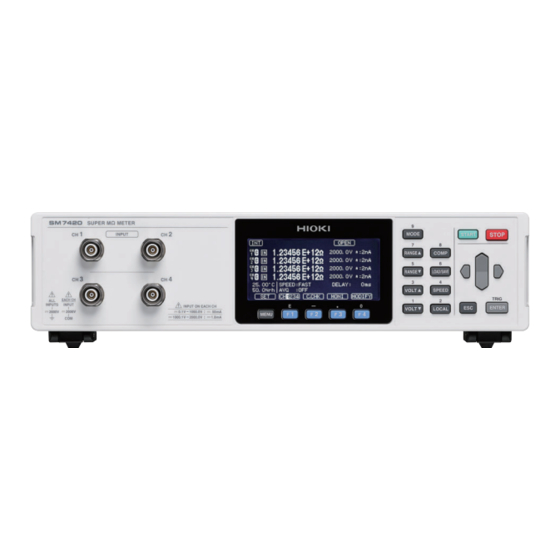
Page 21: Names And Functions Of Parts
Names and Functions of Parts 1.2 Names and Functions of Parts Front Measurement terminals (INPUT) Screen Connect measurement leads to Monochrome graphic LCD these terminals. See p. 10. Operation keys (p. 19) Measurement Description terminals These are measurement input terminals. Have triaxial structure. - Page 22 Names and Functions of Parts Rear Name Description Reference Power switch Turn on and off the instrument, flipping this switch. p. 31 p. 10 Power inlet Connects the accessory power cord to this inlet. p. 27 These terminals are used to share the GROUND potential of the measurement circuit of the instrument and the external power supply.
- Page 23 Names and Functions of Parts Bottom Stands Right Unfolding and retracting the stands Vent Handle CAUTION Do not apply heavy downward pressure with the stand extended. The stand could be damaged. Left Vent...
- Page 24 Names and Functions of Parts Operation keys These keys also serve as the numeric keypad to enter the numerical values. Description Reference Switches the measurement mode. The mode changes every time the key is pressed in the following order: p. 33 Resistance, Current, Surface resistance, Volume resistance, Liquid volume resistance, and returns back to Resistance.
- Page 25 Names and Functions of Parts Description Reference Stops measurement. – • Moves the cursor to another setting item or digit. p. 25 • Changes numerical values. • Cancels the setting. – • Returns to the measurement screen from other screens. Confirms the setting.
-
Page 26: Screen Configuration And Operation
Screen Configuration and Operation 1.3 Screen Configuration and Operation The screens of the instrument consists of the measurement screens and the settings screens. For information about the settings screen, see “Displaying the various menu settings screens” (p. 23). Measurement screens Press the [MONI] to switch between the 1-channel display and the 4-channel display. -
Page 27: Settings Screens
Screen Configuration and Operation Displayed items Content Description Reference Displays the presently set trigger. Trigger setting [INT] Internal trigger p. 46 [EXT] External trigger Sampling data Appears during the sampling data. – Self-calibration Appears during the self-calibration. p. 47 Appears when the contact check function is enabled. Contact check p. -
Page 28: Basic Key Operation
Basic Key Operation 1.4 Basic Key Operation Displaying measurement screen You can also press the key to return to the measurement screen. Displaying the various menu settings screens This section shows an example of switching the measurement screen to the [SYS] screen. -
Page 29: Selecting Settings Items
Basic Key Operation List of menu settings screens [MEAS] screen [C.CHK] screen Configuring settings for measurement Configuring settings for open correction and contact check [COMP] screen [ELEC] screen Configuring settings for measured value judgment Configuring settings for calculating resistivity [SYS] screen [I/O] screen... -
Page 30: Methods For Changing Numerical Values
Basic Key Operation Methods for changing numerical values The two options available are: using the cursor keys and using the numeric keypad. Move (If using the cursor keys) Move to the next digit (left or right) Confirm Change the numerical value (up or down) Cancel (If using the numeric keypad) - Page 31 Basic Key Operation...
-
Page 32: Preparing For Measurement
Preparing for Measurement 2.1 Connecting Power Cord to Instrument Be sure to read “Before connecting the power cord to the instrument” (p. 10) beforehand. Check that the power switch is in the off position ( ). Check that the power voltage is in the range indicated on the rear, and then connect the power cord to the power inlet. -
Page 33: Connecting Measurement Leads To Instrument
Connecting Measurement Leads to Instrument 2.2 Connecting Measurement Leads to Instrument Be sure to read “Before connecting the measurement leads and electrode to the instrument” (p. 10) beforehand. The measurement leads are optional. (p. 4) Required leads: Measurement lead (red) and measurement lead (black) ×1 each Front INPUT terminal Rear... -
Page 34: Connecting Humidity Sensor
Connecting Humidity Sensor 2.4 Connecting Humidity Sensor Be sure to read “Before connecting the Humidity Sensor to the instrument” (p. 10) beforehand. The Humidity Sensor is optional. (p. 5) Required sensor: Model Z2011 Humidity Sensor Install the Humidity Sensor close to the object to be measured. This enables the environment, temperature and humidity, around the object also to be measured simultaneously. -
Page 35: Outputting Measurement Current Value Converted To Analog Signal
Outputting Measurement Current Value Converted to Analog Signal 2.5 Outputting Measurement Current Value Converted to Analog Signal Use the D/A output function to log the output together with the output of other measuring instruments such as recorders. A voltage of 2.0 V is output if the measured current value reaches the maximum display value of the present current range’s scale. -
Page 36: Turning On/Off Instrument
The self-test is executed automatically after startup (ROM/RAM check). If an error is displayed on the LCD screen, the instrument is necessary to be repaired. Please contact your authorized Hioki distributor or reseller. See “Error display and solution” (p. 136). -
Page 37: Inspection Before Use
2.7 Inspection Before Use Before using the instrument, verify that it operates normally to ensure that no damage occurred during storage or shipping. If you find any damage, contact your authorized Hioki distributor or reseller. Verifying the instrument and the peripheral devices... -
Page 38: Basic Measurement
Basic Measurement 3.1 Setting Measured Value Display Mode Press the MODE key to switch the measured value display modes. Resistance value measurement mode Current value measurement mode (initial screen) Surface resistivity measurement mode Liquid volume resistivity measurement Volume resistivity measurement mode mode Measurement conditions must be set to measure surface resistivity and volume resistivity. -
Page 39: Changing Display Notation
Setting Measured Value Display Mode Changing display notation MENU [MEAS] Procedure to display the settings screen: (Measurement screen) key > Press the key to change the value. [EXP] Exponential notation: Displays values, expressed in exponential notation, to five Ω decimal places. (Example: 1.00000E+16 ) (default setting) [UNIT] Decimal notation:... -
Page 40: Setting Voltage Value For Resistance Calculation
Setting Voltage Value for Resistance Calculation 3.2 Setting Voltage Value for Resistance Calculation Set the voltage value for resistance calculation. The numerical value can also be changed with the numeric keypad. See “Methods for changing numerical values” (p. 25). Press the VOLT▲... -
Page 41: Setting Measurement Speed
Setting Measurement Speed 3.3 Setting Measurement Speed Settings for measurement speed are shared by all channels. The slower the measurements, the more the accuracy improves. See “Current measurement accuracy” (p. 121). Some measurement speeds are not available depending on the current range setting. If the measurement speed cannot be changed, check the current ranges of the other channels. -
Page 42: Changing Current Range
Changing Current Range 3.4 Changing Current Range Change the current range if the measured current value or the measured resistance value exceeds the measurable range or if measurement with another measure accuracy is preferred. See “Current measurement accuracy” (p. 121). No setting for resistance range is required. -
Page 43: Connecting Measurement Leads Or Electrode To Object To Be Measured
Connecting Measurement Leads or Electrode to Object to Be Measured 3.5 Connecting Measurement Leads or Electrode to Object to Be Measured Connect the measurement leads or electrode (both are optional) to the object to be measured. Measurement fixtures can be available depending on the object to be measured. Using measurement fixtures is •... -
Page 44: Starting/Stopping Measurement
Starting/Stopping Measurement 3.6 Starting/Stopping Measurement Be sure to read “Before performing a measurement” (p. 11) beforehand. Internal trigger (INT) (default Pressing the START key starts the measurement. setting) STOP Pressing the key stops the measurement. External trigger (EXT) Pressing the START key sets the instrument waiting for a trigger. -
Page 45: Basic Measurement Examples
Basic Measurement Examples 3.8 Basic Measurement Examples Measurement of the resistance value of a capacitor is explained with an example. Examples of setting contents Measured value display mode Resistance value measurement mode (initial screen) [0.1 V] Voltage value for resistance calculation Current range [AUTO] Measurement speed... - Page 46 Basic Measurement Examples Press the F1 key [AUTO]; otherwise, press the RANGE▲ key and the RANGE▼ key to set the range to [AUTO]. (p. 37) Connect the clip type test lead to both terminals of the capacitor. Apply a voltage using an external power supply. Press the START key to start the measurement.
- Page 47 Basic Measurement Examples...
-
Page 48: Applied Measurement
Applied Measurement 4.1 Starting Measurement After Measured Value Becomes Stable (Delay Function) For the external trigger (EXT), set the time from when the trigger is input to when the measurement starts. (The delay time elapses after the trigger is input each time.) With the trigger source setting set to the internal trigger (INT), no delay time elapses after the trigger. -
Page 49: Reducing Variation In Measured Values (Average Function)
Reducing Variation in Measured Values (Average Function) 4.2 Reducing Variation in Measured Values (Average Function) The average for the set number of measured values will be displayed as the result. This function can reduce the variation in the measured values. Set it on the Measurement screen. Press the [MODIFY] to enable the measurement conditions to be changed. - Page 50 Reducing Variation in Measured Values (Average Function) [HOLD] is selected, set the average frequency. 2 to 255 times (default setting: 2 times) Pressing the [EDIT] enables the numerical value to be changed. Confirm Move to the next digit (left or right) Change the numerical value Cancel...
-
Page 51: Changing Measurement Starting Conditions (Trigger Function)
Changing Measurement Starting Conditions (Trigger Function) 4.3 Changing Measurement Starting Conditions (Trigger Function) The following two methods are available to set the measurement starting conditions. External trigger After the START key is pressed, when the external trigger signal is input, the measurement starts. -
Page 52: Maintaining Measurement Accuracy (Self-Calibration Function)
Maintaining Measurement Accuracy (Self-Calibration Function) 4.4 Maintaining Measurement Accuracy (Self- Calibration Function) The self-calibration corrects the offset voltage and the gain drift in the internal circuit. The default setting is [ON]: thus, the self-calibration is executed automatically every time the set interval elapses (default setting: 600 s). - Page 53 Maintaining Measurement Accuracy (Self-Calibration Function) [ON] is selected, set the self-calibration interval. 1 s to 600 s (default setting: 600 s) Pressing the [EDIT] enables the numerical value to be changed. Move to the next digit (left or right) Confirm Change the numerical value (up or down)
-
Page 54: Contact Check (Various Settings)
Contact Check (Various Settings) 4.5 Contact Check (Various Settings) While measuring the insulator, if a measurement fixture of the measurement system is not in contact with the measured object, even defective insulation may be wrongly determined to be pass. To avoid such erroneous judgment, the contact check function is used to check if the measurement fixture is brought into contact with the object to be measured. - Page 55 Contact Check (Various Settings) Setting of [FREQ] Set the frequency of the signal applied during the open correction or the contact check. 245 kHz, 300 kHz (default setting: 300 kHz) Setting of [WORK.C] Set the capacitance of the objects to be measured. [LOW] If the capacitance of the objects to be measured is 10 pF or less [NORMAL]...
- Page 56 Contact Check (Various Settings) Setting of [CABLE] Set the cable length. [AUTO] The cable length is automatically detected and set. [EDIT] Optional numerical values can be set. 0.5 m to 3.0 m (Can be set in increments of 0.1 m, default setting: 1.0 m) Pressing the [EDIT] enables the...
-
Page 57: Correction Function)
Canceling Capacitance of Measurement Fixture (Fixture Capacitance Open Correction Function) 4.6 Canceling Capacitance of Measurement Fixture (Fixture Capacitance Open Correction Function) Be sure to read “Before performing the open correction” (p. 12) beforehand. This function measures the capacitance of a measurement fixture with its terminals open. The fixture capacitance open correction function can reduce the impact of residual impedance of the measurement fixture (such as lead or fixture) and improve the measurement accuracy. -
Page 58: Contact Check (Executing Contact Check, Setting Reference Value)
Contact Check (Executing Contact Check, Setting Reference Value) 4.7 Contact Check (Executing Contact Check, Setting Reference Value) Be sure to read “Before performing a measurement” (p. 11) beforehand. The contact check can be performed with the cable connected to the object to be measured. The instrument judges the contact check result to be pass or fail by detecting a difference of the capacitance between that obtained when the cable is open and that obtained during the contact check. - Page 59 Contact Check (Executing Contact Check, Setting Reference Value) Procedure to display the settings screen: (Measurement screen) MENU key > [C.CHK] [CH1234] The channel switches to another in the order from CH1 through CH4 every time the is pressed. Select whether to perform contact check or not. [ON] Enabled (The contact check is executed before starting measurement.) [OFF]...
-
Page 60: Setting Resistivity Calculation (Resistivity Measurement Function)
Setting Resistivity Calculation (Resistivity Measurement Function) 4.8 Setting Resistivity Calculation (Resistivity Measurement Function) Use of an electrode conforming to JIS or other standards enables the instrument to directly calculate the surface resistivity and volume resistivity from the measured resistance. Set the measured value display mode to [RS] (surface resistivity), [RV]... - Page 61 Setting Resistivity Calculation (Resistivity Measurement Function) Procedure to display the settings screen: (Measurement screen) MENU key > [ELEC] [CH1234] The channel switches to another in the order from CH1 through CH4 every time the is pressed. Select whether to set the model name of the option or to directly enter the electrode constant.
- Page 62 Setting Resistivity Calculation (Resistivity Measurement Function) [EDIT] is selected The numerical value can also be changed with the numeric keypad. See “Methods for changing numerical values” (p. 25). Set the diameter of the main electrode (D1). 0.0 mm to 100.0 mm (Can be set in increments of 0.1 mm, default setting: 50.0 mm) Move to the Confirm next digit...
-
Page 63: Further Accelerating Measurement
Further Accelerating Measurement (Function of Updating Drawing During Measurement) Set the electrode constant (K). 0.01 to 999.99 (Can be set in increments of 0.01, default setting: 500.00) Confirm Move to the next digit (left or right) Change the Cancel numerical value (up or down) 4.9 Further Accelerating Measurement (Function of Updating Drawing During... -
Page 64: Measurement Methods Suitable For Various Objects To Be Measured
Measurement Methods Suitable for Various Objects to Be Measured Insulation resistance objects to be measured vary in material, shape, electrical characteristics, and other properties, and the suitable insulation resistance measurement method varies depending on the object. This chapter describes suitable insulation resistance measurement methods for different objects. 5.1 Measuring Components of Circuits Measurement principle Generally, insulation resistance is measured by measuring the current that flows from a terminal... -
Page 65: Measurement With Use Of A Measurement Fixture
Measuring Components of Circuits Measurement with use of a measurement fixture Design the circuit in the order that the currents flowing through the outside of all the objects to be measured flow through the guard circuit and connect the guard circuit to the GUARD terminal of the instrument. -
Page 66: Measurement Without Use Of A Measurement Fixture
Measuring Components of Circuits Measurement without use of a measurement fixture Connect the optional Pin Type Lead or Clip Type Lead to the object to be measured and perform measurement. Both the measuring leads do not have a guard on the end connected to the power supply terminal but have a guard on the other end connected to the INPUT terminal. -
Page 67: Automatic Measurement
Measuring Components of Circuits Automatic measurement If you have many objects or points to be measured, “automatic measurement” is useful. The function performs measurement by automatically switching objects, measurement fixtures, or measurement terminals to be measured. For automatic measurement, the switch timing must be aligned with the instrument operation. The following are the 2 methods to align the timing. -
Page 68: Measuring Flat Sample
Measuring Flat Sample 5.2 Measuring Flat Sample Measuring insulation resistance of an object with no terminals installed requires something that can function as terminals to be attached on the object. The measurement method varies depending on the type of the terminal. What function as terminals It must be possible to switch the objects to be measured easily. -
Page 69: Measurement Using An Electrode For A Flat Sample
(the functional role of the guard electrode) A guard is required for measuring volume resistance and surface resistivity. Hioki provides Model SME-8310 Plate Sample Electrode and SME-8311 Electrodes for Flat Sample as options. Both devices consists of 3 electrodes: “main electrode,” “counter electrode,” and “guard electrode.”... - Page 70 Measuring Flat Sample (2) Measurement with the guard electrode Because the current flowing along the surface of the measured object flows out through the guard electrode to the external power supply, the current flowing across the object in the thickness direction can be separately measured with accuracy.
-
Page 71: Measuring A Liquid Sample
Measuring a Liquid Sample 5.3 Measuring a Liquid Sample To measure the volume resistance of a liquid sample, insert an electrode with a fixed shape in the liquid sample or use an electrode that can also function as the container for the liquid sample. When using an electrode for liquid samples Example of connection Guard electrode... -
Page 72: Measurement With Use Of Shielding Box
Measurement With Use of Shielding Box 5.4 Measurement With Use of Shielding Box Be sure to read “Before using the shielding box” (p. 11) beforehand. Measurement of high insulation resistance, which requires to measure current with high-sensitivity, may be unstable due to ambient noise or inductive current. Thus, measurement objects to be measured must be placed in a shielding box. -
Page 73: Measuring Current
Connect the negative side of the object to be measured to the INPUT terminal of the instrument. Use a shielded wire for the measurement lead connected to the INPUT terminal so that it is not affected by inductive interference such as noise. SM7420 INPUT − Negative side... -
Page 74: Judging Measured Value (Comparator Function)
Judging Measured Value (Comparator Function) The comparator function judges whether measured values are within or out of a range defined by an upper and lower limits set previously. The judgment is displayed as follows on the screen. [Hi] (Upper limit) < (Measured value) [IN] (Lower limit) ≤... - Page 75 If the upper limit and lower limit settings are set to [ON], set the numerical value. Pressing the [EDIT] enables the numerical value to be changed. Move to the Confirm next digit (left or right) Change the numerical value (up or down) Cancel The numerical value can also be changed with the numeric keypad.
-
Page 76: Setting Judgment Sound
Setting Judgment Sound 6.1 Setting Judgment Sound Select whether to use a judgment sound for the measurement results. Procedure to display the settings screen: COMP Select the respective buzzer sounds for Hi judgment, IN judgment, and Lo judgment. [OFF] (No sound, default setting), [TYPE1], [TYPE2], [TYPE3] Selecting [TYPE1], [TYPE2], or [TYPE3]... -
Page 77: Confirming Judgment Results
Confirming Judgment Results 6.2 Confirming Judgment Results An indicator appears on the measurement screen according to the judgment results. The instrument outputs judgment results through the EXT I/O connector. The On signal corresponding with a judgment result is outputted. If the measured value is smaller than the upper limit value but greater than the lower limit value that are previously set If the measured value is greater than the upper limit value that is previously set If the measured value is smaller than the lower limit value that is previously set... -
Page 78: Saving And Loading Settings (Panel Saving And Loading)
Saving and Loading Settings (Panel Saving and Loading) The present settings can be saved to the memory of the instrument (panel saving function). The saved settings can be loaded from the memory by pressing the keys or sending communication commands (panel loading function). The instrument can save a maximum of 50 settings. -
Page 79: Saving Settings (Panel Saving Function)
Saving Settings (Panel Saving Function) 7.1 Saving Settings (Panel Saving Function) This function saves the settings that are currently set. Procedure to display the settings screen: LOAD/SAVE Select the panel number to be saved, and press the key [SAVE]. The confirmation dialog box is displayed. (If saving it as a new one) (If saving it, replacing the exist one with the new one with the same name) The panel name can be changed. -
Page 80: Loading Settings (Panel Loading Function)
Loading Settings (Panel Loading Function) 7.2 Loading Settings (Panel Loading Function) This function loads the settings that are saved. Procedure to display the settings screen: LOAD/SAVE Select the panel number to be loaded, and press the [LOAD] or the ENTER key. -
Page 81: Changing Panel Name
Changing Panel Name 7.3 Changing Panel Name The panel name can be changed. Procedure to display the settings screen: LOAD/SAVE Select the number of the panel whose name you want to change, and press the [RENAME]. Change the panel name. [0-9] Numeric input mode is enabled. -
Page 82: Deleting Panel Contents
Deleting Panel Contents 7.4 Deleting Panel Contents This section describes the procedure for deleting saved settings. Procedure to display the settings screen: LOAD/SAVE Select the panel number to be deleted, and press the key [CLEAR]. The confirmation dialog box is displayed. To cancel the delete operation, press the [CANCEL] or the... - Page 83 Deleting Panel Contents...
-
Page 84: System Setting
System Setting 8.1 Setting Sound of Key Operation You can set the sound of key operation to be enabled or disabled. Procedure to display the settings screen: (Measurement screen) MENU key > [SYS] [ON] The operation sound is emitted (default setting). [OFF] The operation sound is not emitted. -
Page 85: Disabling Key Operation (Key Lock Function)
Disabling Key Operation (Key Lock Function) 8.2 Disabling Key Operation (Key Lock Function) You can disable the key operation. Procedure to display the settings screen: (Measurement screen) MENU key > [SYS] Press [ALL] [MENU] to disable the key operation (to activate the key lock function). [ALL] Disables all of the key operation except the MENU... -
Page 86: Browsing, Deleting, And Outputting Internal Memory Data
Browsing, Deleting, and Outputting Internal Memory Data Inputting the KEYLOCK signal disables all the key operation. (The key lock function cannot be deactivated by using the operation keys.) Key operation is disabled while the KEYLOCK signal state is on. Switching the signal to the off state deactivates the key lock function. 8.3 Browsing, Deleting, and Outputting Internal Memory Data The memory function can automatically store up to 999 measured values in the internal memory... -
Page 87: Browsing And Deleting Data
Browsing, Deleting, and Outputting Internal Memory Data Browsing and deleting data Procedure to display the screen: (Measurement screen) MENU key > [SYS] Press the [LIST]. The internal memory list is displayed. You can scroll the list by pressing the up or down cursor key. You can scroll the list one screen at a time by pressing the right or left cursor key. -
Page 88: Setting D/A Output
Setting D/A Output Press the [CLEAR]. The confirmation dialog box is displayed. To cancel the deletion of memory data, press the [CANCEL] or the key. Press the key [OK]. The memory data is deleted. 8.4 Setting D/A Output Select a channel used for D/A output. Procedure to display the settings screen: (Measurement screen) MENU key >... -
Page 89: Adjusting Screen Contrast
Adjusting Screen Contrast 8.5 Adjusting Screen Contrast The visibility of the screen may not be clear at some ambient temperatures. The visibility of the screen can be adjusted by adjusting the screen contrast. Procedure to display the settings screen: (Measurement screen) MENU key >... -
Page 90: Changing Power Frequency Setting (Power Frequency Setting Function)
Changing Power Frequency Setting (Power Frequency Setting Function) 8.7 Changing Power Frequency Setting (Power Frequency Setting Function) You can change the setting for the power frequency. This enables stable measurement without being affected by the power frequency. Procedure to display the settings screen: MENU key >... -
Page 91: Initializing Settings (Reset)
Initializing Settings (Reset) 8.8 Initializing Settings (Reset) The reset function has 2 methods. For details of items that are to be reset, see “Default setting list” (p. 87). Procedure to display the settings screen: (Measurement screen) MENU key > [SYS] Select the reset method. -
Page 92: Default Setting List
Initializing Settings (Reset) Default setting list Setting Screen display Default setting Reference Voltage value for resistance calculation EXT.V 0.1 V p. 35 Measurement speed SPEED SLOW2 p. 36 Range RANGE AUTO p. 37 Measurement Delay function DELAY 0.0 ms p. 43 screen Average function p. -
Page 93: Checking Instrument Information
Checking Instrument Information Setting Screen display Default setting Reference Communication Interface INTERFACE RS-232C p. 109 RS-232C communication speed SPEED 9600 bps p. 113 GP-IB address ADDRESS p. 114 GP-IB delimiter DELIMITER USB mode USB MODE COMM p. 110 Data output function DATA OUT p. -
Page 94: External Control (Ext I/O)
External Control (EXT I/O) Be sure to read “Before controlling the instrument externally” (p. 12) beforehand. Connecting the instrument to an external device such as a PLC (programmable logic controller) via the EXT I/O terminal on the rear of the instrument enables you to control the instrument in the following ways: •... -
Page 95: Switching Current Sink (Npn) / Current Source (Pnp)
Switching Current Sink (NPN) / Current Source (PNP) 9.1 Switching Current Sink (NPN) / Current Source (PNP) Be sure to read “Before controlling the instrument externally” (p. 12) beforehand. Use the EXT I/O MODE selector switch to change the type of the PLC that can be supported. By factory default, the external I/O setting is set to NPN. -
Page 96: Instrument-Side Connector Pin Assignment
External Input/Output Terminals and Signals Instrument-side connector pin assignment IMPORTANT The connector shell is connected (allows conduction) to the metallic enclosure and the protective earth pin of the power inlet. Note that it is not isolated from the ground. Signal name Function Logic TRIG... - Page 97 External Input/Output Terminals and Signals Signal name Function Logic LO (1) Comparator judgment of Lo for CH1 Level IN (2) Comparator judgment of IN for CH2 Level HI (3) Comparator judgment of Hi for CH3 Level LO (3) Comparator judgment of Lo for CH3 Level C_CHECK_GO (4) Contact check result for CH4...
-
Page 98: Functions Of Each Of The Signals
External Input/Output Terminals and Signals Functions of each of the signals IMPORTANT • The EOM and INDEX signals are turned on when the instrument starts up. • To avoid misjudgment, determine judgments by checking all of the HI, IN and LO signals. Input signal OPEN Executes an open correction. -
Page 99: Timing Chart
Timing Chart 9.3 Timing Chart The levels of each signal represent whether the contacts are in the on or the off state. With the current source (PNP) setting, the voltage level of the corresponding output becomes high when an output state is on, and low when a state is off. If the output signal setting is set to the current sink (NPN), the voltage levels, high and low are inverted. - Page 100 Timing Chart Item Contents Time START pulse width 200 µs or more STOP pulse width 200 µs or more TRIG pulse width 200 µs or more TRIG acceptable time from START 0 µs or more Delay time for INDEX and EOM 200 µs or less INDEX time ([Contact check delay time] + [Contact checking time] +...
- Page 101 Timing Chart (3) Contact check or open correction (independent execution) C_CHECK, OPEN INDEX C_CHECK_GO (1)~ ON/OFF ON/OFF C_CHECK_GO (4), OPEN_GO Item Contents Time C_CHECK, OPEN pulse width 1 ms or more Delay time for INDEX and EOM 1.5 ms or less INDEX time Contact-checking time or open correction time (10 ms) EOM time...
-
Page 102: Output Signal Status On Start-Up
Timing Chart Output signal status on start-up After turning on the instrument, when the screen changes from the start-up screen to the measurement screen, the EOM and INDEX signals change to ON. Turn on the instrument Status Splash screen Measurement screen Self-calibration INDEX Judgment result... -
Page 103: Internal Circuit Configuration
Internal Circuit Configuration 9.4 Internal Circuit Configuration NPN setting Do not connect any external power supply to Pin 8. The instrument PLC, etc. ISO_5 V Ω Ω TRIG Output C_CHECK Common EXT I/O MODE Internally isolated selector PLC, etc. power supply Input Ω... -
Page 104: Electrical Specifications
Internal Circuit Configuration PNP setting Do not connect any external power supply to Pin 8. The instrument PLC, etc. ISO_5 V Ω Ω Output TRIG C_CHECK Common EXT I/O MODE Internally isolated selector power supply PLC, etc. Input Ω Zener voltage 30 V C_CHECK _GO (1) ISO_COM Common... -
Page 105: Examples Of Connection
Internal Circuit Configuration Examples of connection Examples of input circuit connection SM7420 SM7420 Input Input ISO_COM ISO_COM Connection to switch Connection to relay SM7420 SM7420 Input Output Input Output ISO_COM Common ISO_COM Common Connection to PLC output (NPN output) Connection to PLC output (PNP output) - Page 106 Internal Circuit Configuration Examples of output circuit connection SM7420 SM7420 Output Output 50 mA max 50 mA max ISO_COM ISO_COM 30 V max Connection to relay Connection to LED SM7420 Output SM7420 Output 50 mA max Negative Output logic output...
-
Page 107: Assembling Male Connector For Ext I/O (Accessory)
Assembling Male Connector for EXT I/O (Accessory) 9.5 Assembling Male Connector for EXT I/O (Accessory) The male connector for the EXT I/O is supplied along with the instrument. Assemble the connector, referring to the figure below. • Use a shielded wire for the cable that connects the EXT I/O connector to a device, such as PLC. Otherwise, the system may malfunction due to noise. -
Page 108: Ext I/O Terminal Input And Output Testing
EXT I/O Terminal Input and Output Testing 9.6 EXT I/O Terminal Input and Output Testing The output signal can be switched on and off manually. In addition, the condition of the input signal can be monitored on the screen. (EXT I/O test function) Procedure to display the settings screen: MENU key >... -
Page 109: Settings For External Input And Output
Settings for External Input and Output 9.7 Settings for External Input and Output The following items for the external input and output can be set. Setting Description Reference Trigger logic An effective edge can be selected for the TRIG signal. p. -
Page 110: Trigger Filter
Settings for External Input and Output Trigger filter This setting can be used to accept the TRIG signal from the EXT I/O terminal only if the TRIG signal remains in the on state during the set response time. Procedure to display the settings screen: MENU key >... -
Page 111: Go-Signal Outputting Logic Level
Settings for External Input and Output GO-signal outputting logic level This setting can specify the outputting logic level for the C_CHECK_GO and V_CHECK_GO signals, which are used with the contact check and voltage monitor on, respectively (No logic level of the OPEN_GO signal is inverted). Procedure to display the settings screen: MENU key >... -
Page 112: Eom Signal Output Mode
Settings for External Input and Output EOM signal output mode This setting can be used to specify the output method for the EOM (end of measurement) signal. Procedure to display the settings screen: MENU key > [I/O] Select whether to maintain the EOM signal in the on state or to switch it to the off state after the set time has elapsed. - Page 113 Settings for External Input and Output...
-
Page 114: Communications (Usb, Rs-232C, Gp-Ib)
The interface set on the screen is enabled. For details about the communication commands, refer to Communication Command Instruction Manual included in the accompanying CD. They can also be downloaded from the Hioki website. For the specifications, see “11.4 Interface Specifications” (p. 130). -
Page 115: Usb Interface
When the instrument is first connected to a computer, it is necessary to install the dedicated USB driver. If the driver has already been installed, skip the following procedure. The accompanying CD contains the USB driver. It can also be downloaded from the Hioki website. Installation procedure Install the USB driver before connecting the instrument to a computer with a USB cable. -
Page 116: Setting The Instrument
USB Interface Setting the instrument MENU [IF] Procedure to display the settings screen: key > Press the key [USB]. Set the USB mode. [KEYBOARD] Outputs measured values through the USB cable connected to the computer. Measured values are output to a text editor or spreadsheet in the same way as data is entered with a keyboard. -
Page 117: Rs-232C Interface
When connecting instrument to computer Use a cross cable with 9-pin female D-sub connectors installed at both ends. Cross connection D-sub 9-pin, female D-sub 9-pin, female PC/AT compatible Instrument computer PIN No. PIN No. Recommended cable: Hioki Model 9637 RS-232C Cable (1.8 m) -
Page 118: Setting The Instrument
RS-232C Interface Setting the instrument MENU [IF] Procedure to display the settings screen: key > Press the key [RS232C]. Set a transmission speed (baud rate). 4800 bps, 9600 bps, 19200 bps, 38400 bps, 115200 bps (default value: 9600 bps) Press the [↓] [↑] to select a value. -
Page 119: Gp-Ib Interface
GP-IB Interface 10.4 GP-IB Interface Connecting the GP-IB cable Be sure to read “Before connecting the communication cable to the instrument” (p. 12) beforehand. Connect the GP-IB cable to the GP-IB Connector. After connecting the cable to the instrument and another device, be sure to fasten the screws. - Page 120 GP-IB Interface Set a delimiter. LF, CR+LF (default setting: LF)
-
Page 121: Settings Common To Interfaces
Settings Common to Interfaces 10.5 Settings Common to Interfaces Outputting measured values (data output function) (RS-232C and USB only) Select whether to output the measured values automatically via each of the interfaces. Setting this function to [ON] disables the communication commands to control the instrument because the data output exclusively uses the interface. -
Page 122: Displaying Communication Commands (Communication Monitor Function)
Settings Common to Interfaces Displaying communication commands (communication monitor function) The send and receive state of commands and queries can be checked on the screen. Procedure to display the settings screen: MENU key > [IF] [ON] Displays commands. [OFF] Does not display any commands. (default setting) The communication monitor is displayed on the measurement screen when communication starts. -
Page 123: Control By Using Commands
Control by Using Commands 10.6 Control by Using Commands For the description (communication message reference) of the communication commands and queries, refer to the Communication Command Instruction Manual, which is included in the accompanying CD. Remote state The instrument is placed in the remote state during the USB, RS-232C, or GP-IB communication, displaying [RMT] on the settings screen. -
Page 124: Specifications
Specifications 11.1 General Specifications Operating environ- Indoors, Pollution Degree 2, altitude up to 2000 m (6562 ft.) ment Operating tempera- Temperature 0°C to 40°C (32°F to 104°F) ture and humidity Humidity 80% RH or less (no condensation) Storage temperature Temperature −10°C to 50°C (14°F to 122°F) and humidity Humidity 80% RH or less (no condensation) -
Page 125: Input/Output/Measurement Specifications
Input/Output/Measurement Specifications 11.2 Input/Output/Measurement Specifications The underlined values are the default settings. The set values are retained even after the instrument is turned off. Basic specifications Number of channels Measurement meth- Current measurement method Maximum rated volt- 2000 V DC age to earth Ω... -
Page 126: Accuracy Specifications
Conditions of guaranteed Guaranteed accuracy 1 year accuracy period Guaranteed accuracy 1 year period from adjust- ments made by Hioki Temperature and hu- 23°C±5°C (73°F±9°F), 80% RH or less midity for guaranteed accuracy Warm-up time At least 30 minutes Power frequency 50 Hz / 60 Hz ±2 Hz... - Page 127 Input/Output/Measurement Specifications Measurement time Settings of contact check function and comparator function Contact-checking time 2.3 ms 0.0 ms Comparator measurement time 0.2 ms 0.0 ms Setting of measure- Internal integration 50 Hz 60 Hz ment speed time FAST 4.1 ms 4.1 ms 2 ms FAST2...
- Page 128 Input/Output/Measurement Specifications Specifications of Model Z2011 Humidity Sensor Temperature ±0.5°C (10°C to 60°C) measurement Measuring temperature exceeding the range enclosed in parentheses above reduces this accuracy accuracy as follows: Add 0.015°C/°C (from −40°C inclusive to 10°C exclusive) Add 0.02°C/°C (from 60°C exclusive to 80°C inclusive) Humidity ±3% RH (20°C to 30°C, 20% RH to 90% RH) measurement...
-
Page 129: Function Specifications
Function specifications 11.3 Function specifications The underlined values are the default settings. The set values are retained even after the instrument is turned off. Measured value dis- Displayed item An item to be displayed can be selected between the following: play mode resistance, current, surface resistivity, volume resistivity, and liquid volume resistivity. - Page 130 Function specifications Contact check delay Operation details Sets the duration from when the TRIG signal is input until the start function of the contact check. Setting range 0 ms to 9999 ms (in increments of 1 ms) Channel setting Separate setting for each channel Start of the current measurement delays using the longest delay time among the settings of all the channels.
- Page 131 Function specifications Contact check func- Operation details Judges the contact condition by comparing a measured value with tion the judgment reference value. Operation method Capacity measurement method by applying a high frequency sig- Outputs measurement signals for each channel separately Execution method and using the signals to evaluate objects to be measured on a pass/fail basis for each channel individually.
- Page 132 Function specifications Resistivity measure- Operation details The surface resistivity and the volume resistivity are calculated from ment function the electrode constant previously entered. Channel setting Separate setting for each channel Setting Items Surface resistivity (Diameter of the main electrode) / (Inter- nal diameter of the counter electrode) Flat sample volume resistivity (Diameter of the main electrode)
- Page 133 Function specifications Panel saving, panel Operation details Saves and loads the measurement conditions specified by the loading panel number. Numbers of panels Panel name 10 characters (Alphabets or numbers) Saved contents Measured value display mode, setting of voltage value for re- sistance calculation, measurement speed, range, trigger mode, delay, average, contact check, self-calibration setting, resistivity measurement settings, comparator, judgment sound, fixture ca-...
- Page 134 Function specifications Measurement timing Trigger measurement (example of one channel) C. check de- Delay Calculating Calculating Waiting for Contact Measuring Outputting Outputting Waiting for lay (external (external measured comparison TRIG check current INDEX TRIG only) only) value value Detecting contact error When contact check delay times of channels are different from each other •...
-
Page 135: Interface Specifications
Interface Specifications 11.4 Interface Specifications The underlined values are the default settings. The set values are retained even after the instrument is turned off. Communication con- Remote control, measured value output tents Connector Series B receptacle Electrical specifica- USB2.0 (Full Speed) tions Class (mode) CDC class (COM mode: COMM) -
Page 136: External I/O Specifications
External I/O Specifications Remote functions Operation details If communication is performed through RS-232C, USB or GP-IB, the function changes the instrument status to remote and disables the key operation from the front panel. To deactivate the remote control, follow the ways listed below: •... - Page 137 External I/O Specifications TRIG filter func- Operation details Processes signals only when the input signal remains in the on state tion during the response time. Setting ON / OFF Response time 1 ms to 500 ms TRIG logic setting Operation details Sets the start edge for the TRIG signal.
-
Page 138: Maintenance And Service
The buzzer volume cannot be adjusted for this instrument. – volume. The measured Run self-calibration. values are not If an error is displayed, internal damage may have occurred. Contact p. 47 displayed. your authorized Hioki distributor or reseller. - Page 139 Troubleshooting Measurement items Troubleshooting Confirm Possible causes, solution Reference Electromagnetic induction affects the Measurement measured values. Self-built p. Appx.11 leads → Guard the cable, as close as possible to the measured object. Characteristics have changed Temperature depending on the temperature. Measured values Measured has not been...
- Page 140 Troubleshooting Communication items The operation can be checked smoothly by using the communication monitor (p. 116). Troubleshooting Confirm Possible causes, solution Reference Connection cannot be established. → Check the connector insertions. → Check that the settings of the interfaces are correct. → Before using the USB, install drivers in the control instruments. [RMT] is not → Use the cross cable when RS-232C...
-
Page 141: Error Display And Solution
Troubleshooting Error display and solution System errors (requiring repair) Error No. Display Cause Solution ERR:001 Backup data error Backup data error ERR:002 RAM error CPU RAM error ERR:003 Memory read/write error Memory read/write error Calibration error in the current ERR:004 Calibration error measurement block A/D communication ERR:005... - Page 142 Troubleshooting Measurement errors Error No. Display Cause Solution The measured value exceeds None Current Over Range Set the correct range. the current measuring range. The measured value exceeds the temperature measuring The temperature is too high to be None +Over°C range.
-
Page 143: Inspection, Repair And Cleaning
To ensure the product can be used over the long term, it is recommended to replace these parts on a periodic basis. When replacing parts, please contact your authorized Hioki distributor or reseller. The service life of parts varies with the operating environment and frequency of use. Parts are not guaranteed to operate throughout the recommended replacement cycle. -
Page 144: Appx. 1 Internal Circuits
Appendix Appx. 1 Internal Circuits Appx. -
Page 145: Appx. 2 Changes In Current Running Through Insulator
Changes in Current Running through Insulator Appx. 2 Changes in Current Running through Insulator When measuring insulation resistance, a large current flows as a voltage is applied, and gradually the current becomes smaller, not reaching a constant value. This is caused by charge current, absorption current, and leak current, and is generally called dielectric absorption. -
Page 146: Noise
Countermeasures Against Noise Appx. 3 Countermeasures Against Noise (1) Effects of induction noise A lot of noise is generated from power cords, fluorescent lights, solenoid valves, and computer displays. Below are noise sources that may affect resistance measurement. 1. Electrostatic coupling between a high-voltage line and a measurement lead 2. - Page 147 Similarly, noise may also be injected from control lines of the controller. Noise that penetrates from the power of the controller, or generated from a DC-DC converter installed the controller, penetrates the measurement instrument through a USB cable or EXT I/O wire (Figure 5). RS-232C Controller EXT I/O (Computer, SM7420 PLC) INPUT GP-IB External power OUTPUT supply...
- Page 148 Countermeasures Against Noise Conductive noise can be monitored with the Hioki 3145 Noise HiLogger while measures are taken. If the penetration path has been specified, follow the measures shown in Figure 6. Isolation Controller (Computer, SM7420 PLC) INPUT Common mode filter in...
-
Page 149: Appx. 4 Using Instrument With
Connect the shorting plug to the GUARD terminal and the GROUND terminal. Connect an object to be measured to the OUTPUT terminal of Model SM7110/SM7120. Connect the GUARD terminal of Model SM7110/SM7120 and the COM terminal of Model SM7420 with each other. -
Page 150: Connecting Objects To Be Measured And The Switching Unit To The Instrument
Two methods are available depending on the status of the objects to be measured. If the objects to be measured are grounded Because the OUTPUT terminal of the external power supply is grounded, connect the switching unit to the INPUT terminal. Switching unit SM7420 INPUT Objects to be measured External power supply... -
Page 151: Selecting Relays To Be Installed In The Switching Unit
Assembling Switching Unit for Object to Be Measured Selecting relays to be installed in the switching unit Important specifications for relays Switching voltage and dielectric strength “Maximum switching voltage” and “dielectric strength between contacts and between a contact and a coil” must be sufficiently high with respect to the instrument’s set voltage. -
Page 152: Circuit Diagram Of The Switching Unit
Hioki for use with the Super Megohm Meter. In addition, as for the cables between the instrument and the switching unit and between the switching unit and objects to be measured, employ the cables that are custom-made by Hioki for use with the Super Megohm Meter. -
Page 153: Current-Limiting Resistor
Assembling Switching Unit for Object to Be Measured Example of terminal for adding relay and resistor Thread mount TEFLON terminal block FN-1-1 (Effective screw depth is 3 mm) manufactured by Mac-Eight Metal (nut) TEFLON Metal terminal (Used as guard shown in (Insulator) (Used as metal terminal shown figure on previous page) -
Page 154: Appx. 6 Modifying Measurement Lead
Modifying Measurement Lead Appx. 6 Modifying Measurement Lead When modifying the tip of the Hioki-made measurement lead, follow the procedure below: When stripping off the jacket or braided conductor, take care not to break the wires or short-circuit them with each other. - Page 155 Modifying Measurement Lead Strip off the insulator with a knife, etc. Braided conductor for the guard wire Black conductive vinyl Completely remove the conducting vinyl. Strip off the insulator with a knife, etc. Insulator Black conductive vinyl Completely remove the conducting vinyl. Conductor Cover the guard wire with a heat shrinkable tube and make it shrink.
-
Page 156: Rack
(Stands: M3 × 6 mm, sides: M4 × 6 mm, when attaching a rack mounting plate: M4 × 10 mm) If you lost any screws or find that any screws are damaged, please contact your Hioki distributor for a replacement. Rack mounting plate (EIA) 2 × f4.5 mm 2 ×... - Page 157 Mounting Instrument in Rack Rack mounting plate (JIS) 2 × f4.5 mm 2 × C2 2 × R3 32.5 mm 330 mm 40 mm 460 mm 480 mm M3 × 6 mm Remove the stands from the bottom of the instrument, and the screws from the sides (4 near the front).
-
Page 158: Appx. 8 Dimensional Diagram
Dimensional Diagram Appx. 8 Dimensional Diagram Unit: mm 15±0.3 75±0.5 330±2 32±0.5 21.5±0.5 Appx. - Page 159 Dimensional Diagram Unit: mm 23.5±0.5 277±0.5 Appx.
- Page 160 Index EXT I/O test functions ..........103 Analog output ............. 30, 83 Automatic measurement........... 62 Average function ............44 Fixture capacitance open correction function ... 52 Flat sample ............... 63 Backlight ..............84 Block diagram ............ Appx.1 GP-IB connector ............17 GP-IB interface ............
- Page 161 Index Measurement example ..........40 Setting Measurement screen ..........21 Measurement speed ..........36 Measurement speed ..........36 Voltage value for resistance calculation ....35 Measurement starting conditions......46 Setting conditions Measurement terminals ..........16 Changing the panel name ........76 Measuring current.............
-
Page 162: Melrose, Ma
Test Equipment Depot - 800.517.8431 - 99 Washington Street Melrose, MA 02176 TestEquipmentDepot.com...
Need help?
Do you have a question about the SM7420 and is the answer not in the manual?
Questions and answers