Hioki BT4560 Instruction Manual
Battery impedance meter
Hide thumbs
Also See for BT4560:
- Instruction manual (62 pages) ,
- Instruction manual (167 pages) ,
- Instruction manual (60 pages)

Related Manuals for Hioki BT4560


Summary of Contents for Hioki BT4560
- Page 1 BT4560 Instruction Manual BATTERY IMPEDANCE METER Aug. 2018 Revised edition 1 BT4560A981-01 18-08H...
-
Page 3: Table Of Contents
Contents Introduction ..........1 Customization „ Registered trademark ........1 of Measurement Verifying Package Contents ..... 1 Safety Information ........3 Conditions Operating Precautions ......6 Setting the Measurement Overview Starting Conditions (Trigger Functions) ........37 „ Setting the trigger ........37 Product Overview and Features ..11 „... - Page 4 Contents Saving and Reading Communication Measurement (RS-232C, USB) Conditions Features of Interface ...... 95 „ Specifications ..........95 Saving the Setting Conditions Connecting and Setting Method ... 96 (Panel Saving Function) ....58 „ Using the USB interface ......96 Reading the Setting Conditions „...
- Page 5 Contents Appendix Appx. 1 Measurement Parameters and Calculation Formula ....A1 Appx. 2 Four-terminal Pair Method ..A2 Appx. 3 Cautions When Making Your Own Measurement Probe .........A4 Appx. 4 Measurement Probe Structure and Extension ..A6 Appx. 5 Measurement Value in the Four-terminal Measurement (Difference in Measurement Value Due...
- Page 6 Contents...
-
Page 7: Introduction 1
Introduction Introduction Thank you for purchasing the HIOKI BT4560 Battery Impedance Meter. To obtain maximum performance from the instrument, please read this manual first, and keep it handy for future reference. Registered trademark Microsoft and Windows are either registered trademarks or trademarks of Microsoft Corporation in the United States and other countries. - Page 8 Verifying Package Contents Options (p. A12) The following options are available for the instrument. Contact your authorized Hioki distributor or reseller when ordering. L2002 Clip Type Probe L2003 Pin Type Probe Z2005 Temperature Sensor 9637 RS-232C Cable (9pin-9pin/1.8 m)
-
Page 9: Safety Information
Safety Information Safety Information This instrument is designed to conform to IEC 61010 Safety Standards, and has been thoroughly tested for safety prior to shipment. However, using the instrument in a way not described in this manual may negate the provided safety features. Before using the instrument, be certain to carefully read the following safety notes. - Page 10 Safety Information Symbols on the instrument Indicates cautions and hazards. When the symbol is printed on the instrument, refer to a corresponding topic in the Instruction Manual. Indicates the ON side of the power switch. Indicates the OFF side of the power switch. Indicates a grounding terminal.
- Page 11 Safety Information Measurement categories To ensure safe operation of measurement instruments, IEC 61010 establishes safety standards for various electrical environments, categorized as CAT II to CAT IV, and called measurement categories. DANGER • Using a measuring instrument in an environment designated with a higher- numbered category than that for which the instrument is rated could result in a severe accident, and must be carefully avoided.
-
Page 12: Operating Precautions
• Before using the instrument for the first time, verify that it operates normally to ensure that no damage occurred during storage or shipping. If you find any damage, contact your authorized Hioki distributor or reseller. Instrument installation Installing the instrument in inappropriate locations may cause a malfunction of instrument or may give rise to an accident. - Page 13 Operating Precautions Installation To prevent overheating, be sure to leave the specified clearances around the instrument. CAUTION • Do not install the instrument with any side except the bottom facing down. • Ventilation holes for heat radiation are provided on the side, bottom and rear panels of the instrument.
- Page 14 Operating Precautions Before connecting the power cord WARNING • Before turning the instrument on, make sure the supply voltage matches that indicated on its power connector. Connection to an improper supply voltage may damage the instrument and present an electrical hazard. •...
- Page 15 Operating Precautions CAUTION • To avoid damage to the instrument, do not apply voltage or current to temperature sensor terminal. • To prevent cable damage, do not step on cables or pinch them between other objects. Do not bend or pull on cables at their base. •...
- Page 16 • Keep discs inside a protective case and do not expose to direct sunlight, high temperature, or high humidity. • Hioki is not liable for any issues your computer system experiences in the course of using this disc.
-
Page 17: Product Overview And Features
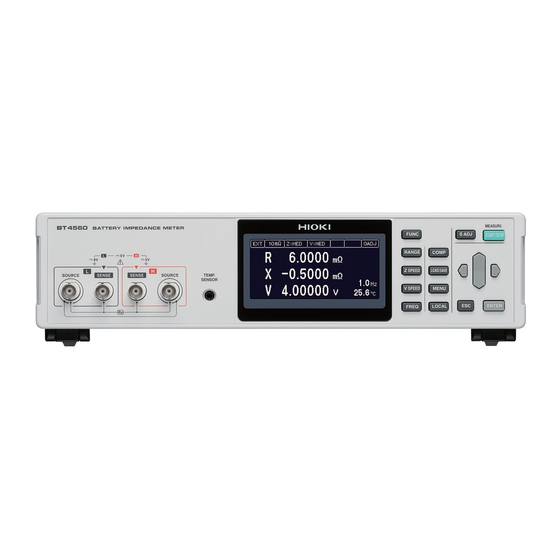
Overview 1.1 Product Overview and Features The BT4560 is a variable-frequency impedance meter. This instrument is equipped with a highly accurate voltmeter and a temperature measurement function, and optimal for quality control of batteries. This instrument has the circuit configuration with high noise immunity, and thus, can provide stable measurement even at production sites. - Page 18 Names and Functions of Parts 1.2 Names and Functions of Parts Front Measurement terminal Connect the measurement probe. Refer to p. 8. Voltage detection terminal (SENSE-L, SENSE-H) Current generation terminal (SOURCE-H) Current detection terminal Operating keys (p. 14) (SOURCE-L) Temperature sensor terminal Display Connects the Z2005 Monochrome graphic LCD...
- Page 19 Names and Functions of Parts Bottom panel Stands Vents Side Raising/closing the stand CAUTION Do not apply heavy downward pressure with the stand extended. The stand could be damaged.
- Page 20 Names and Functions of Parts Operating keys Description Selects the measurement function (combination of the voltage measurement and the impedance measurement). Sets the measurement range. Sets the measurement speed of impedance. Sets the measurement speed of voltage. Sets the measurement frequency of impedance. Sets the power switch of ON-OFF and the upper and lower limit values ,etc.
-
Page 21: Screen Configuration And Operation
Screen Configuration and Operation 1.3 Screen Configuration and Operation The instrument is configured with the measurement screen and each setting screen. Measurement screen Settings screen Measurement frequency setting screen When [EXIT] is selected, display returns to the Comparator setting screen measurement screen. - Page 22 Measurement Flow 1.4 Measurement Flow Be sure to refer to “Operating Precautions” (p. 6) before using the instrument. Installing, connecting, and turning power on Install (p. 7). Connect the measurement probe and the temperature sensor (p. 18). Connect the power cord (p. 17). Connect the measurement probe and the Connect the temperature sensor (p.
-
Page 23: Preparation
Preparation 2.1 Connecting the Power Cord Check that the power switch Power inlet Outlet (rear) of the instrument is OFF ( ). Check that the power voltage is in the range indicated on the rear, and then connect the power cord to the power inlet. - Page 24 Connecting the Measurement Probe and Temperature Sensor (Optional) 2.2 Connecting the Measurement Probe and Temperature Sensor (Optional) The measurement probe and the temperature sensor are optional. (p. A12) Connect the four-terminal cable to the instrument Connection method Check the orientation of the groove Align the groove in the BNC Turn the BNC connector to the in the BNC connector and ensure...
-
Page 25: Turning The Power On Or Off
2.4 Inspection Before Use Before using the instrument, verify that it operates normally to ensure that no damage occurred during storage or shipping. If you find any damage, contact your authorized Hioki distributor or reseller. Verifying the instrument and the peripheral devices... - Page 26 Inspection Before Use...
-
Page 27: Basic Measurement
Basic Measurement 3.1 Selecting the Measurement Functions Set the measurement functions. Parameters Measurement items Parameters Measurement items Impedance Reactance θ Phase angle Voltage Resistance Temperature By pressing (FUNC) the measurement functions are switched. For the selectable functions, refer to Table below. RXVT θ... -
Page 28: Functions
Selecting the Measurement Range 3.2 Selecting the Measurement Range Ω Ω Ω Set the measurement range of impedance (3 m , 10 m , 100 m The voltage and the temperature have a single range respectively. Thus, setting is not necessary. Use the measurement range of impedance when the impedance measurement value exceeds the present range or when changing the measurement accuracy. -
Page 29: Setting The Measurement Speed
Setting the Measurement Speed 3.3 Setting the Measurement Speed Set the measurement speed (FAST, MED, SLOW) in the impedance measurement and the voltage measurement. The slower the measurement speed is, the more accurate are the results. Set the measurement speed of impedance measurement (Z) By pressing SPEED) the measurement speed in the impedance measurement is switched. -
Page 30: Setting The Measurement
Setting the Measurement Frequency 3.4 Setting the Measurement Frequency Setting the measurement frequency. (0.1 Hz to 1050 Hz) Press (FREQ). (Measurement frequency setting screen appears.) The selected digit is displayed in reverse black and white, with a bar under the digit enabled to be set. - Page 31 Setting the Measurement Frequency When the measurement time is long (Display of the Progress Bar) When the impedance measurement time is long (more than approx. 1 second), the progress bar is displayed on the right side of the measuring screen which is in operation. During sample delay (p.
- Page 32 Performing the Zero Adjustment 3.5 Performing the Zero Adjustment Remove the residual components due to offset and the measurement environment. Be sure to perform the zero adjustment before the impedance measurement and the voltage measurement. Performing the zero adjustment Placing the measurement probe (Example: L2002) Place the measurement probe in the same condition as the measurement is performed.
- Page 33 Performing the Zero Adjustment Press ADJ). (The zero adjustment screen appears.) Select [ON]. To the SPOT and ALL selection screen (or) Selection Cancel Select [SPOT] or [ALL]. Performing zero adjustment (or) Selection Cancel When selecting [ALL], the confirmation window opens. Performing all zero adjustment CANCEL: Returns to the measurement screen without execution.
- Page 34 Performing the Zero Adjustment When the zero adjustment is not normally performed When [0 ADJUST ERROR] appears, the proper adjustment is not performed. Check the short-circuit method of the measurement probe and perform the zero adjustment with a proper method so that the zero adjustment data values come within the range given in the table below. Return Impedance measurement...
- Page 35 Performing the Zero Adjustment When measuring while changing the measurement range If measured as below, zero adjustment will not be necessary every time the range is changed. Ω Perform zero adjustment at 3 m range. Save the current condition by panel saving function (p. 58). (Zero adjustment data of the current range will be saved.) Ω...
- Page 36 Checking the Measurement Results 3.6 Checking the Measurement Results Detecting the measurement abnormality When the measurement is not normally performed, the indication expressing the measurement abnormality appears on the screen, and the ERR signal from the EXT.I/O is output. Contact error When the resistance value is greater between SOURCE-H and SENSE-H, or between SENSE-L and SOURCE-L, the contact error appears.
- Page 37 Checking the Measurement Results The guide line in the abnormality detection of the measurement current Target resistance value for abnormality Measurement Place for abnormality Indi- detection abnormality detection cation type Ω Ω Ω range 10 m range 100 m range Measurement Ω...
- Page 38 Checking the Measurement Results Detection sequence of measurement abnormality Error indication judgment Indication CONTACT Contact error between the SOURCE-H and the SENSE-H ERROR H CONTACT Contact error between the SOURCE-L and the SENSE-L ERROR L OVER Over-voltage input error VOLTAGE OVER Voltage limit error V LIMIT...
-
Page 39: Basic Measurement Examples
Basic Measurement Examples 3.7 Basic Measurement Examples In this section, setting the battery cell is explained as an example. Examples of setting contents Measurement functions R, X, V, T Ω Measurement Range 100 m Impedance FAST Measurement measurement speed Voltage measurement SLOW Impedance measurement frequency 1 Hz... - Page 40 Basic Measurement Examples Set the speed of the voltage measurement (V) at [SLOW]. (p. 23) Set the measurement frequency of impedance at 1 Hz. (p. 24) Connect the zero adjustment connection and then perform the all zero adjustment. (p. 26) Connect the battery cell.
- Page 41 Basic Measurement Examples Check the measurement results.
- Page 42 Basic Measurement Examples...
-
Page 43: Customization
Customization of Measurement Conditions 4.1 Setting the Measurement Starting Conditions (Trigger Functions) There are two methods to set the measurement starting conditions, which are described below. When (START/STOP) is pressed or the external trigger signal is input, the External trigger measurement starts. -
Page 44: The Response Of The Measuring Object Is Stable (Sample Delay
Starting the Measurement After the Response of the Measuring Object is Stable (Sample Delay Function) Inputting the external trigger • When inputting from the key On the measurement screen, press (START/STOP) to perform measurement once. • When inputting from the EXT.I/O If the TRIG terminal of the EXT.I/O terminal is short-circuited to ISO_COM, the measurement is performed once. - Page 45 Starting the Measurement After the Response of the Measuring Object is Stable (Sample Delay Function) Setting with the deviation of voltage fluctuation (∆VOLT) Alternating Current response of the battery ∆ VOLT ∆ VOLT Sampling The slope of Alternating Current response is monitored and sampling is started when the slope of deviation (∆VOLT) drops below the set value.
- Page 46 Starting the Measurement After the Response of the Measuring Object is Stable (Sample Delay Function) When selecting [WAVE], set the wavenumber of delay. (0.0 waves to 9.0 waves) Confirm Setting (or) Move to the next digit (left or right) Cancel Changing the numerical value (up and down) When selecting [∆VOLT], set the voltage.
- Page 47 Maintaining Voltage Measurement Accuracy (Self-Calibration Function) 4.3 Maintaining Voltage Measurement Accuracy (Self-Calibration Function) This function compensates the offset voltage and the gain drift in the internal part of the circuit, to improve the voltage measurement accuracy. To satisfy the instrument’s measurement accuracy, the self-calibration is required. Be sure to perform it.
-
Page 48: Stabilizing The Measurement Values (Average Function)
Stabilizing the Measurement Values (Average Function) 4.4 Stabilizing the Measurement Values (Average Function) The arithmetic mean for the set number of measurement values will be displayed as the result. This function can reduce the fluctuation of the measurement values. This function can apply only to the impedance measurement. - Page 49 Compensating the Potential Slope Due to Electric Discharge (Slope Correction Function) 4.5 Compensating the Potential Slope Due to Electric Discharge (Slope Correction Function) During impedance measurement, the measurement signal may drift due to characteristics of the battery and input impedance of the measuring instrument. This function performs compensation for linear drift.
- Page 50 Compensating the Potential Slope Due to Electric Discharge (Slope Correction Function) Press (MENU). (Settings screen is displayed.) Select [MEAS] tab. Selection Select [ON] or [OFF]. Confirm (or) Selection Cancel...
-
Page 51: Preventing The Overcharge Due
Preventing the Overcharge due to Measurement Signal (Voltage Limit Function) 4.6 Preventing the Overcharge due to Measurement Signal (Voltage Limit Function) This function prevents the battery from getting overcharged due to the applied signal when measuring impedance. If the voltage of the object to be measured is higher compared to the set voltage, impedance will not be measured and the message [OVER V LIMIT] will be displayed. -
Page 52: To Measurement Signal (Voltage Limit Function)
Preventing the Overcharge due to Measurement Signal (Voltage Limit Function) When selecting [ON], set the voltage. (0.01 V to 5.00 V) Confirm Selection (or) Move to the next digit (left or right) Cancel Changing the numerical value (up and down) - Page 53 Prevents Charging and Discharging due to the Measurement Signal (Measurement Signal Zero Cross Stop Function) 4.7 Prevents Charging and Discharging due to the Measurement Signal (Measurement Signal Zero Cross Stop Function) This function performs the process of stopping the applied measurement signal at zero cross during impedance measurement to prevent charging and discharging of the object to be measured.
- Page 54 Prevents Charging and Discharging due to the Measurement Signal (Measurement Signal Zero Cross Stop Function) Select [ON] or [OFF]. Confirm (or) Selection Cancel...
-
Page 55: Judging Measurement
Judging Measurement Results (Comparator Function) The function judges that the measured value is in the range of Hi (upper limit value < measured value), or IN (lower limit value ≤ measured value ≤ upper limit value), or Lo (measured value < lower limit value) compared to the preset upper and lower limit value. - Page 56 Turning the Comparator Function ON and OFF 5.1 Turning the Comparator Function ON and OFF Press (COMP). (The setting screen appears.) Select [SYST] tab. Selection Select [ON] or [OFF]. Confirm Selection (or) Cancel...
-
Page 57: Setting The Upper And Lower
Setting the Upper and Lower Limit Value 5.2 Setting the Upper and Lower Limit Value When making the comparator function effective, set the upper and lower limit value, which are used for the judgment. The following describes the setting method, taking R, X, V as the examples. Setting examples Ω... -
Page 58: Limit Value
Setting the Upper and Lower Limit Value Ω Ω Set the upper limit value of at 7.5000 m , and the lower limit value at 7.0000 m Upper limit value Lower limit value Confirm Move to the next digit (left or right) (or) Changing the numerical value (up and down) - Page 59 Setting the Upper and Lower Limit Value When [CLR] is selected and confirmed, the set value is displayed as [-.----] and is disabled. Disabled parameters are not judged. Confirm Selection (or) Cancel Ω Ω When set to 100 m range (Minimum resolution 0.001 m Rounded off to the minimum digits set.
-
Page 60: Voltage Is Judged With The Absolute Value
Voltage is Judged with the Absolute Value 5.3 Voltage is Judged with the Absolute Value The upper and lower limit of voltage is judged with the absolute values. θ (R, X, Z and cannot be set to be judged with absolute values.) Press (COMP). -
Page 61: Checking The Judgment With
Checking the Judgment with Sound 5.4 Checking the Judgment with Sound Select whether to use a judgment sound of the measurement results. : The buzzer does not sound. Hi • Lo : When the judgment result is Hi • Lo, the buzzer sounds (three short sounds). : When the judgment result is IN, the buzzer sounds (long sound). -
Page 62: Checking The Judgment Result
Checking the Judgment Result 5.5 Checking the Judgment Result The indicator appears at the left of the parameters on the measurement screen depending on the judgment result. Each judgment result, and the comprehensive judgment result of all the parameters are output to the EXT.I/O. -
Page 63: Conditions
Saving and Reading Measurement Conditions (Panel Saving and Loading) The present measurement conditions are saved to the memory of the instrument (panel saving function), and the measurement conditions are read from the memory by the key operation, communication command transmission, and external control. (Panel loading function) The instrument can save 126 panels of measurement conditions at a maximum. - Page 64 Saving the Setting Conditions (Panel Saving Function) 6.1 Saving the Setting Conditions (Panel Saving Function) Saves the measurement conditions that are currently set. Press (LOAD/SAVE). (The panel screen appears.) Select the number of the panel that will be saved. Confirm Selection (or)
- Page 65 Saving the Setting Conditions (Panel Saving Function) When [+5] is selected, the next 5 panel numbers are displayed. When [-5] is selected, the previous 5 panel numbers are displayed.
- Page 66 Reading the Setting Conditions (Panel Loading Function) 6.2 Reading the Setting Conditions (Panel Loading Function) Reads the measurement conditions that are saved. Press (LOAD/SAVE). (The panel screen appears.) Select the number of the panel that will be read. Confirm Selection (or) Cancel...
-
Page 67: Deleting The Contents Of The Panel
Deleting the Contents of the Panel 6.3 Deleting the Contents of the Panel Deletes saved measurement conditions. Press (LOAD/SAVE). (Panel screen is displayed.) Select a panel number to be deleted. Confirm Selection (or) Cancel Select [CLEAR]. Confirm Selection (or) Cancel Opens confirmation window. - Page 68 Deleting the Contents of the Panel...
-
Page 69: System Setting
System Setting 7.1 Making the Key Operation Effective or Ineffective Makes the key operation except for (START/STOP) ineffective. Ineffective Press (MENU). (The setting screen appears.) Select [SYST] tab. Selection Select [ON]. Confirm Selection (or) Cancel [LOCK] appears on the measurement screen, and the key operation becomes ineffective. - Page 70 Making the Key Operation Effective or Ineffective Effective Press (LOCAL) and hold for at least 5 seconds. [LOCK] disappears on the measurement screen, and the key operation becomes effective.
-
Page 71: Setting The Sound Of The Key Operation Effective Or Ineffective
Setting the Sound of the Key Operation Effective or Ineffective 7.2 Setting the Sound of the Key Operation Effective or Ineffective Make the sound of the key operation effective or ineffective. Press (MENU). (The setting screen appears.) Select [SYST] tab. Selection Select [ON]... -
Page 72: Adjusting The Contrast Of The Screen
Adjusting the Contrast of the Screen 7.3 Adjusting the Contrast of the Screen The visibility of the screen may not be clear at some ambient temperatures. The visibility of the screen can be adjusted by adjusting the screen contrast. Press (MENU). -
Page 73: Adjusting The Backlight
Adjusting the Backlight 7.4 Adjusting the Backlight The brightness of the backlight can be adjusted for the illumination of the installation location. When the trigger source is set from the external trigger, if the status with no operation continues for 1 minute, the brightness of the backlight will become dim automatically. Press (MENU). -
Page 74: System Testing
System Testing 7.5 System Testing I/O TEST The input and output test of the EXT. I/O can be performed. The ON and OFF of the output signal can be switched manually. In addition, the status of the input signal can be monitored on the screen. - Page 75 System Testing KEY TEST This test can check that the key is not defective. Press (MENU). (The setting screen appears.) [TEST] Select tab. Selection Select [KEY TEST]. Selection To Testing screen Press the keys of the instrument to test the keys. (Check that all the key names on the screen are reversed.) The screen returns to the key test screen.
- Page 76 System Testing LCD TEST This test can check that there is no dead pixel on the display screen. Press (MENU). (The setting screen appears.) Select [TEST] tab. Selection Select [LCD TEST]. Selection To Testing screen The explanation screen for test is displayed. Execute Return Press ENTER, and confirm that all screen indicators lights up and off repeatedly.
- Page 77 System Testing ROM TEST This test can check that the program data of the instrument is normal. Press (MENU). (The setting screen appears.) Select [TEST] tab. Selection Select [ROM TEST]. Selection Execute Test the ROM. The screen returns to the ROM testing screen. Return...
- Page 78 System Testing COMMAND MONITOR Response of communications command and queries can be displayed on the screen. Press (MENU). (Settings screen is displayed.) Select [TEST] tab. Selection Select [COMMAND MONITOR]. Selection Execute Confirm the contents of the communication commands. Press (LOCAL). (Key operation is enabled.) (or) Return...
-
Page 79: Confirm Instrument Information
Confirm Instrument Information Scroll the screen if the confirmation screen becomes full. Press (LOCAL). (Key operation is enabled.) Scroll the screen. Scroll 7.6 Confirm Instrument Information The software version and serial number are displayed. Press (MENU). (Settings screen is displayed.) Select [INFO] tab. -
Page 80: Initializing (Reset)
Initializing (Reset) 7.7 Initializing (Reset) The reset function has two kinds of methods. Initializing the settings to the factory default excluding the interface setting, zero NORMAL adjustment values, and panel saving data. SYSTEM Initializing the settings to the factory default excluding the interface setting. For details of resetting items, refer to “Initial setting table”... - Page 81 Initializing (Reset) The confirmation window appears. : Executes reset. CANCEL : Returns to the measurement screen without execution. When NORMAL is selected Confirm Selection When SYSTEM is selected Confirm Selection The display returns to the measurement screen after the reset process is completed.
- Page 82 Initializing (Reset) Initial setting table Initialization by Initialization by Returns to Panel normal reset system reset Default default when the Item Save/ setting (Communication: (Communication: power supply is Load *RST SYSTem:RESet turned ON Ω Range 10 m Measurement frequency 1000 Hz Mea- Voltage measurement sure-...
- Page 83 Initializing (Reset) Initialization by Initialization by Returns to Panel normal reset system reset Default default when the Item Save/ setting (Communication: (Communication: power supply is Load *RST SYSTem:RESet turned ON Screen contrast − Screen brightness − Key-lock Key operation buzzer −...
- Page 84 Initializing (Reset)
- Page 85 External Control (EXT.I/O) Using the EXT.I/O terminals on the rear of the instrument, the instrument can be controlled by external devices such as PLC. The instrument can also be controlled by outputting the measurement ending signal and the judgment result signal, and by inputting the measurement starting signal by using the EXT.I/O connector on the rear.
-
Page 86: External Input/Output Terminals And Signals
The type of the PLC (programmable controller) that can be supported is changed by the NPN/PNP switch. The factory default is set to the NPN. NPN/PNP switch setting BT4560 input circuit Corresponding to sink output Corresponding to source output BT4560 output circuit... - Page 87 External Input/output Terminals and Signals Signal name Function Logic START (TRIG) Starting the measurement (external trigger) Edge 0ADJ_ALL All zero adjustment Edge STOP Stopping the measurement Edge LOAD1 Loading number Bit 1 Level LOAD3 Loading number Bit 3 Level LOAD5 Loading number Bit 5 Level (Don’t use)
- Page 88 External Input/output Terminals and Signals Functions of each signal Input signal START (TRIG) When START (TRIG) signal is switched from OFF to ON, measurement is performed once on the edge. This is only effective when TRIGGER SOURCE is set to the external [EXT] side. 0ADJ_ALL When the 0ADJ_ALL signal is switched from OFF to ON, all zero adjustment (p.
- Page 89 External Input/output Terminals and Signals Output signal When a measurement error (p. 30) occurs, the output changes to ON. (In the case of the overrange, the output is OFF.) ERR is updated just before the EOM signal. When ERR is ON, all of the comparator judgment outputs become OFF. In the case of a measurement error: ERR output changes to ON In the case of a normal measurement: ERR output changes to OFF PASS...
-
Page 90: Timing Chart
Timing Chart 8.2 Timing Chart The levels of each signal indicate the ON/OFF status of the contacts. In the case of the current source (PNP) setting, the signal levels are the same as the voltage level of the EXT.I/O terminals. In the case of the current sink (NPN) setting, the High and Low voltage levels are reversed. - Page 91 Timing Chart θ In the case of measurement functions (R, X, T), (Z, , T) TRIG Measurement Measurement current current abnormal- Over-voltage input Contact error Contact error fault detection ity (monitored error detection detection detection Voltage drift detection between t-2 and t-3, and between t10 and t8 and t11.) Switching mea-...
- Page 92 Timing Chart (2) When the internal trigger [INT] is set θ θ In the case of measurement functions (R, X, V, T), (Z, , V, T), (R, X, T), (Z, , T) INDEX Judgment result Judgment results: HI, IN, LO, PASS, FAIL, ERR In the case of measurement functions (V, T) INDEX Judgment...
- Page 93 Timing Chart Item Contents Time (approximately) Remarks Calculation time Measurement frequency: 1 kHz, Z measurement in impedance 70 ms speed: SLOW, Slope correction: representative measurement value of ON f: Measurement frequency, M: Sample delay t10 Sample delay (1÷f)×M* +0.005 s setting wave number For the setting wave number, refer to (p.
- Page 94 Timing Chart Operation when the self-calibration setting is [MANUAL] The CAL signal is input, and the self-calibration is started immediately. Even if the TRIG signal is input during the self-calibration, the self-calibration is continued. In this case, the trigger signal is held and then the measurement is started after the completion of the self-calibration. When the CAL signal is input during the measurement, the CAL signal is held and then the self-calibration is started after the completion of the measurement.
- Page 95 Timing Chart Timing of the panel loading When the TRIG signal is used LOAD0 to LOAD5 Panel 1 Panel 2 More than 1 ms TRIG 84 ms Status Panel 1 Load processing Panel 2 is measuring Panel 2 IMPORTANT The timing to identify the panel number is not when trigger is input (TRIG:ON), but when it reads the LOAD signal right before the measurement starts.
- Page 96 Timing Chart Taking-in flow with the external trigger With the external trigger, the diagram indicates the flow from the starting of the measurement to the taking-in of the judgment result or the measured values. The instrument outputs the EOM signal immediately after the judgment results (HI, IN, LO, PASS, FAIL, ERR) have been determined.
-
Page 97: Internal Circuitry
Internal Circuitry 8.3 Internal Circuitry NPN setting Do not connect external power supply to 8 pin. The instrument PLC, others ISO_5V Ω Ω START (TRIG) Output 0ADJ_ALL Common EXT.I/O MODE Internally isolated selector power supply PLC, others Ω Input Zener voltage 30 V RorZ_HI ISO_COM ISO_COM... - Page 98 Internal Circuitry PNP setting Do not connect external power supply to 8 pin. The instrument PLC, others ISO_5V Ω Ω Output START (TRIG) 0ADJ_ALL Common EXT.I/O MODE Internally isolated selector power supply PLC, others Input Ω Zener voltage 30 V RorZ_HI ISO_COM Common...
- Page 99 Internal Circuitry Examples of connection Examples of input circuit connection BT4560 BT4560 Input Input ISO_COM ISO_COM Connection to switch Connection to relay BT4560 BT4560 Input Output Input Output ISO_COM Common ISO_COM Common Connection to PLC output (NPN output) Connection to PLC output (PNP output)
-
Page 100: Checking The External Control
Checking the External Control 8.4 Checking the External Control Testing the inputs/outputs (EXT.I/O testing functions) The output signal can be switched ON and OFF manually. In addition, the condition of the input signal can be monitored on the screen. For details, refer to “I/O TEST” (p. 68). -
Page 101: Features Of Interface
The communication interface can be used for the following. • Controlling the instrument using commands and acquiring data. • Using application software. The command table and the application software can be downloaded from the attached CD or our website (http://www.hioki.com/). Specifications Connector Series B receptacle Electrical Specifications USB2.0 (pseudo COM port) -
Page 102: Connecting And Setting Method
If the driver has already been installed, for example, due to using products from other manufacturers, the following procedure is not necessary. The USB driver can be downloaded from the attached CD or our website (http://www.hioki.com/). Installation procedure Perform the installation before connecting between the instrument and the computer with the USB cable. If they already connected, unplug the USB cable. - Page 103 Connecting and Setting Method IMPORTANT The instrument’s USB port is a pseudo COM port. In the case of the communication, it is necessary to set the speed as well as the RS-232C. In the COM port setting, the COM port number that is allocated to the USB port varies with the computer in use.
- Page 104 Use crossing cable of D-sub9 Pin Female - D-sub9 Pin Female. Cross connection D-sub 9 Pin Female D-sub 9 Pin Female Computer/ Instrument side AT compatible computer Pin No. Pin No. Recommended cable: Model 9637 RS-232C Cable (1.8 m) manufactured by HIOKI...
- Page 105 Connecting and Setting Method Setting the transmission speed (Common for USB, RS‑232C) The instrument sets the transmission speed (baud rate) of the interface. It is necessary to set the transmission speed when either the USB communication or the RS-232C communication is used. Press (MENU).
-
Page 106: Controlling The Communication And Acquiring The Data
Controlling the Communication and Acquiring the Data 9.3 Controlling the Communication and Acquiring the Data For the description (communication message reference) of the communication commands and queries, refer to the Communication Command Instruction Manual for the Application Software, which is attached. Remote state/Local state During the communication, the instrument becomes the remote status, and [RMT]... -
Page 107: Specifications
Specifications 10.1 Specifications of Measurement Functions Impedance measurement Measurement signal Constant current AC signal Measurement method Four-terminal pair method Measurement terminal structure Measurement terminal SOURCE-H terminal Current generation terminal function SOURCE-L terminal Current detection terminal SENSE-H terminal Voltage detection terminal SENSE-L terminal Voltage detection terminal Measurement items... - Page 108 Specifications of Measurement Functions Measuring current/DC load (DC load is the offset current that is applied to the measuring object when measuring the impedance.) Ω Ω Ω range 10 m range 100 m range Measurement current 1.5 A rms ±10% 500 mA rms ±10% 50 mA rms ±10% DC load current...
- Page 109 Specifications of Measurement Functions Function θ θ Function structure (R, X, V, T)/(Z, , V, T)/(R, X, T)/(Z, , T)/(V, T) Measurement sequence TRIG Measurement θ Self- , V, T) Contact V calcu- Sample Contact Switching mea- Response calcu- Calibra- signal zero check delay...
-
Page 110: Additional Function
Additional Function Total measurement θ Function (R, X, V, T)/(Z, , V, T) time Response time + Contact checking time × 2 + (Self calibration time) + V sampling time + V calculation time + Measurement circuit switching time+ Sample delay time + Z sampling time + (Measurement signal zero cross detection time) + Z calculation time θ... - Page 111 Additional Function Setting backup Stopping the measurement Function overview Stopping the measurement. Function setting By pressing START/STOP key during measurement, measurement stops. Indicating measurement status Function overview Indicating measurement in operation on the screen. Function operation Indicating measurement in operation on the LCD screen when the measurement time is long (about 1 s or more).
- Page 112 Additional Function Comparator Function overview Comparison functions of measurement and reference values Function setting ON/OFF (Setting each measurement parameter) Adaptive Impedance measurement, voltage measurement measurement Ω Ω Setting the range for Z: 0.0000 m to 120.0000 m θ : -180.000° to 180.000°...
- Page 113 Additional Function Ω Ω Ω Zero adjustment range R -0.1000 m to 0.1000 m (3 m range) Ω Ω Ω -0.3000 m to 0.3000 m (10 m range) Ω Ω Ω -3.000 m to 3.000 m (100 m range) Ω Ω...
- Page 114 Additional Function Voltage limit Function overview Setting the upper limit value of the battery voltage that the impedance measurement is performed. When the battery voltage is higher than the set voltage, impedance measurement will not be performed. (p. 45) Function setting ON/OFF Setting range 0.01 V to 5.00 V (Default setting: 4.20...
- Page 115 Additional Function Key operation buzzer Function overview When the key is operated, the buzzer is beeped. Function setting ON/OFF (When ON is set, the buzzer is beeped.) Setting backup Reset Function overview Cancels the settings Function operation System reset Initializing the settings to the factory default excluding communication setting.
-
Page 116: User Interface
User Interface 10.3 User Interface Display Monochrome graphic LCD 240 × 110 Screen size 94 W × 55 H mm (View area) Backlight White LED Brightness adjustment range: 10% to 100% (in 5% steps) Contrast Adjustment range: 0% to 100% (in 5% steps) 10.4 External Interface Communication Interface Interface types... - Page 117 External Interface EXT.I/O Input signal Input signal • START (TRIG) • STOP • 0ADJ_SPOT • 0ADJ_ALL • LOAD0 to LOAD6 • CAL Photo-coupler Non-voltage contact inputs (corresponding to current sink/source output) insulation Input ON Residual voltage 1 V (Input ON Current 4 mA (reference value)) Input OFF OPEN (Breaking current less than 100 µA) Output signal...
-
Page 118: Accuracy
Accuracy 10.5 Accuracy Guaranteed accuracy conditions Temperature and 23°C±5°C (73°F±9°F), less than 80% RH (no condensation) humidity range Zero adjustment After performing the zero adjustment Measurement status Measuring under the same conditions (probe shape, layout, measurement environment) as the zero adjustment. Unchanging of the probe’s shape during the measurement. - Page 119 Accuracy Accuracy graph Ω Ω Ω • 3 m range (0.1 Hz to 100 Hz), 10 m range, and 100 m range -180 Phase [°] Impedance accuracy excluding α (0.004|R| + 0.0017|X|, 0.004|X| + 0.0017|R|) Ω • 3 m range (110 Hz to 1050 Hz) -180 Phase [°] Impedance accuracy excluding α...
- Page 120 Temperature measurement accuracy Temperature ±0.1°C measurement Temperature coefficient: ±0.01°C/°C (applied to the range of 0°C to 18°C, 28°C to 40°C) (BT4560 only) Temperature ±0.5°C (Measured temperature: 10.0°C to 40.0°C) measurement ±1.0°C (Measured temperature: -10.0°C to 9.9°C, 40.1°C to 60.0°C) (BT4560+Z2005)
-
Page 121: General Specifications
General Specifications V accuracy ±0.0035% rdg. × 3.6 V ±5 dgt. = ±0.000126 V ±0.00005 V = ±0.000176 V (Rounded down to the displayed digit ±0.00017 V) <Measurement condition 2> Measurement range: arbitrary, Measurement speed: arbitrary, Frequency: arbitrary, Measuring object: R=arbitrary, X=arbitrary, V=3.6 V, Instrument’s ambient temperature: 15°C V accuracy ±0.0035% rdg. - Page 122 General Specifications Standards Safety EN61010 EN61326 Class A EN61000-3-2 EN61000-3-3 Effect of radiated radio-frequency At 10 V/m, Impedance measurement ±5%f.s. electromagnetic field At 10 V/m, Voltage measurement ±2% Effect of conducted radio-frequency At 3 V, Impedance measurement ±2%f.s. electromagnetic field Effect of external magnetic field In a magnetic field of 400 A/m, 50/60 Hz Impedance measurement ±6%f.s.
-
Page 123: Service
• When sending the instrument for repair, pack carefully to prevent damage in transit. Include cushioning material so the instrument cannot move within the package. Be sure to include details of the problem. Hioki cannot be responsible for damage that occurs during shipment. - Page 124 Troubleshooting Trouble Confirm Possible causes → Solution Ref. Adjusting buzzer The buzzer volume cannot be adjusted for this instrument. − volume Concerning measurement items Trouble Confirm Possible causes → Solution Ref. Zero adjustment is not correct. → Adjust zero adjustment again by setting p.
- Page 125 Troubleshooting Trouble Confirm Possible causes → Solution Ref. The impact of the wiring shape is too large. Measurement values before → Reduce the loop area formed by the zero adjustment is not − return cable and the measuring object. within the acceptable range. →...
- Page 126 Troubleshooting Concerning communication items The operation can be checked smoothly by using the communication monitor (p. 72). Trouble Confirm Possible causes → Solution Ref. Connection cannot be established. → Check the connector insertions. → Check that the settings of the interfaces are correct.
- Page 127 Troubleshooting Error display and remedy When an error is displayed on the LCD screen, repair is necessary. Please contact your authorized Hioki distributor or reseller. Display Error No. Cause Countermeasures The measurement value OverRange None exceeds the impedance Set the correct range.
- Page 128 The fan does not rotate. Request repairs. OVER CURRENT The device fails. ERR:96 The internal circuit is broken. ERROR Request repairs. The built in battery of the Please contact your authorized VREF B ERROR ERR:97 instrument has to be replaced. Hioki distributor or reseller.
-
Page 129: Inspection, Repair And Cleaning
When replacing parts, please contact your authorized Hioki distributor or reseller. The service life of parts varies with the operating environment and frequency of use. Parts are not guaranteed to operate throughout the recommended replacement cycle. -
Page 130: Discarding The Instrument
Discarding the Instrument 11.3 Discarding the Instrument The instrument uses the CR2032 Coin-shaped lithium battery. Handle and dispose of the instrument in accordance with local regulations. Lithium battery removal WARNING To avoid electric shock, turn off the power switch and disconnect the power cord and measurement cables before removing the lithium battery. -
Page 131: Appx. 1 Measurement
Appendix Appx. 1 Measurement Parameters and Calculation Formula In general, the impedance Z is used to evaluate the characteristics of, for example, circuit components. This instrument measures the voltage vectors of the object being measured against measurement current vectors, and then determines the impedance Z and the phase difference θ from these values. -
Page 132: Appx. 2 Four-Terminal Pair Method
Four-terminal Pair Method Appx. 2 Four-terminal Pair Method This instrument uses the four-terminal pair method as the measurement method. In addition to the characteristics of the AC four-terminal method, which is unaffected by the contact resistance, this is a more accurate method that is unaffected by the magnetic field caused by the measuring current. - Page 133 Four-terminal Pair Method In the four-terminal pair method, the current flows backward (current returns) with the same magnitude as the measuring current in the shields of the SOURCE cables, and then cancels the magnetic field of the measuring current. This method suppresses the induced electromotive force induced at the SENSE terminals, and detects the voltage actually generated in the object being measured.
-
Page 134: Your Own Measurement Probe
Cautions When Making Your Own Measurement Probe Appx. 3 Cautions When Making Your Own Measurement Probe Observe the following precautions when making your own measurement probe. • You must connect the shields of the SOURCE-H and the SOURCE-L. If the shields are not connected, the impedance cannot be measured. - Page 135 Cautions When Making Your Own Measurement Probe • For the shape and position of the measurement probe, give attention to the points in the Figure shown below. Eddy currents from adjacent metal bodies or exogenous inductive noise may cause errors and variations in the measurement value and worsen the repetitive accuracy.
-
Page 136: Appx. 4 Measurement Probe
Extension We can fill requests for probe extensions as a special order. Contact the distributor (store) from which you purchased the instrument or your nearest Hioki sales office. Observe the following precautions when extending the measurement probes by yourself. • Use a thicker lead wire and a minimum length that you can prepare and implement as the extension. -
Page 137: Appx. 5 Measurement Value In The Four-Terminal
Measurement Value in the Four-terminal Measurement (Difference in Measurement Value Due to the Measurement Probe) Reduction method of inductive voltage This instrument is subject to the influence of the inductive voltage because of the measurement of a micro resistance using AC. This inductive voltage means the voltage that is generated by the magnetic induction of the measurement current flowing in the lead wire which may affect the signal system of the measurement. - Page 138 Influence of the Eddy Current Appx. 6 Influence of the Eddy Current Measurement close to the metal body causes an eddy current to flow due to the dynamic magnetic field that is generated by the measurement current of the instrument. This eddy current generates an inductive voltage with a phase opposite to the measurement current in the measurement probe.
- Page 139 Zero Adjustment SENSE-H SENSE-L Constant-current power supply Voltmeter SOURCE-H SOURCE-L Short E =( I × R )+( I × R =(0× R )+(0× R =0 [V] Ω Figure. Conditions where a pseudo 0 is connected To properly carry out the zero adjustment: “Table.
- Page 140 Zero Adjustment Table. Connection method Constant-current power supply Constant-current power supply Voltmeter Voltmeter SOURCE-H SENSE-H SENSE-L SOURCE-L SOURCE-H SENSE-H SENSE-L SOURCE-L Short Short (b) Connecting the spaces between the Hi- (a) Connecting the spaces between SENSE and SOURCE with one point respectively side and the Lo-side respectively.
- Page 141 Zero Adjustment When performing zero adjustment using the zero adjustment board of an accessory: When performing zero adjustment, you must not use a metal plate in substitution for the attached zero adjustment board. The zero adjustment board is structured to connect between the SENSE terminals and the SOURCE terminals with one point.
- Page 142 Measurement Probe (Option) Appx. 8 Measurement Probe (Option) L2002 Clip Type Probe Total length: Approx. 1500 mm Maximum 500 mm 100 mm 400 mm 1000 mm Arrange the probes so that the distance between the SENSE of the probes is the same as the actual object to be measured with the SENSE of the probes (both red and black) facing inwards.
-
Page 143: Appx. 9 Precautions When Making The Switching Unit
Precautions When Making the Switching Unit Appx. 9 Precautions When Making the Switching Unit When placing the switching unit between the instrument and the measuring object, you must make the switching unit with the four-terminal pair connection. Here, when making the switching unit, precautions including performing the four-terminal SOURCE-H pair connection are described. - Page 144 Precautions When Making the Switching Unit When wiring with electrical wires, the loop can be reduced by twisting a pair of electrical wires. (Figure. The Wiring Examples of the Switching Unit (when connecting using electrical wires)) 2a or 2c contact, To latching relay, Contact for a small signal Reduce the loop area...
-
Page 145: Appx. 10 Precautions When
Precautions When Measuring the Battery Appx. 10 Precautions When Measuring the Battery The stability of AC response When measuring the impedance, the response may not stabilize immediately after AC is applied. The sampling using the sample delay function after the AC response is stabilized enables one to measure the impedance accurately. -
Page 146: Measuring The Battery
Precautions When Measuring the Battery Cases that cannot be measured If the voltage exceeds 5 V H terminal BT4560 L terminal Imaginary grounding In case of measuring the cell that has been grounded H terminal BT4560 L terminal... - Page 147 Precautions When Measuring the Battery In case of connecting devices other than this instrument Electronic load H terminal device BT4560 L terminal Imaginary grounding When instruments to be grounded are internally grounded or when capacitance between groundings is large. Cases that can be measured...
-
Page 148: Appx. 11 Calibrating The Instrument
SENSE-H SENSE-L SOURCE-L Ω Figure. Calibrating 0 Shield box Shield The instrument Standard resistor SOURCE-H SENSE-H SENSE-L SOURCE-L Figure. Connecting to the standard resistor Contact your authorized Hioki distributor or reseller for standard resistor to be used for impedance calibration. - Page 149 Calibrating the Instrument Calibrating voltage measurement • Use a generator that can output 7 V DC. • For the connection between this instrument and the generator, refer to Figure illustrated below. • You must not input the AC current of this instrument to the generator. This may cause a malfunction of the generator.
-
Page 150: Appx. 12 Rack Mounting
(Standard: M3 × 6 mm, sides: M4 × 6 mm, when installing rack mounting bracket: M4 × 10 mm) If screws are lost or damaged, contact your authorized Hioki distributor or reseller. Rack Mounting Plate (EIA) 2×C2... - Page 151 Rack Mounting Rack Mounting Plate (JIS) 2×C2 2×φ4.5 mm 2×R3 32.5 mm 330 mm 40 mm 460 mm 480 mm M3 × 6 mm Remove the feed from the bottom of the instrument, and the screws from the sides (four near the front). M4 ×...
- Page 152 Dimensional Diagram Appx. 13 Dimensional Diagram 15 mm 75.2 mm 330 mm±1 mm 32 mm±0.2 mm 21.5 mm±0.2 mm...
- Page 153 Dimensional Diagram 21 mm±0.5 mm 287 mm±0.5 mm...
- Page 154 Dimensional Diagram...
- Page 155 Backlight ..............67 Initializing Battery measurement NORMAL ............... 74 Precaution point ..........A15 SYSTEM ............... 74 BT4560 ............... 1 Initial testing table ............. 76 Input signal ............82, 83 Installation ..............7 Internal circuitry ............91 Connection examples..........93 Calibration .............. A18 Electrical specifications .........
- Page 156 Index Panel loading function ..........60 Temperature sensor terminal ........12 Panel saving function ..........58 Test lead ..............22 Power cord ............... 17 Timing chart .............. 84 Power inlet ..............12 Trigger function ............37 Power supply Input external trigger ..........37 Turn on ..............
Need help?
Do you have a question about the BT4560 and is the answer not in the manual?
Questions and answers