
Related Manuals for Balluff BDG D 60-H020-NUS01-1318-0000-S4L4 Series


Summary of Contents for Balluff BDG D 60-H020-NUS01-1318-0000-S4L4 Series
- Page 1 BDG D_ _60-H020-NUS01-1318-0000-S4L4 deutsch Betriebsanleitung english User’s guide français Notice d’utilisation Manuale d’uso italiano Instrukcja obsługi polski...
- Page 2 www.balluff.com...
- Page 3 BDG D_ _60-H020-NUS01-1318-0000-S4L4 Betriebsanleitung deutsch...
- Page 4 www.balluff.com...
-
Page 5: Table Of Contents
Funktion Anzeigeelemente 4.2.1 Status-LED 4.2.2 LC-Display Typenschild Einbau und Anschluss Einbau vorbereiten Einbau Elektrischer Anschluss Schirmung und Kabelverlegung Inbetriebnahme und Betrieb Inbetriebnahme Betrieb Hinweise zum Betrieb Reinigung Wartung Schnittstelle Störungen, Reparatur, Demontage und Entsorgung Störungsbehebung Reparatur Demontage Entsorgung www.balluff.com deutsch... - Page 6 BDG D_ _60-H020-NUS01-1318-0000-S4L4 Digitale Positionsanzeige Technische Daten Allgemeine Merkmale Umgebungsbedingungen Messbereich Elektrische Merkmale Elektrischer Anschluss Ausgang/Schnittstelle Material Mechanische Merkmale Zulassungen und Kennzeichnungen Zubehör 10.1 Reduzierhülse 14 mm (BAM AD-DG-023-D14/D20-5-01) 10.2 Versorgungskabel, konfektioniert mit geradem M12-Stecker Typenschlüssel deutsch...
-
Page 7: Zu Dieser Anleitung
Übersetzung, bleiben vorbehalten. Verwendete Fachbegriffe und Abkürzungen Mitgeltende Dokumente Weitere Informationen zu diesem Produkt finden Sie unter Standard Input Output www.balluff.com auf der Produktseite z. B. in folgenden Dokumenten: Abbildungen – Datenblatt In dieser Anleitung wird in den Abbildungen die Variante –... -
Page 8: Sicherheitshinweise
Anlage eingebaut und ist für den Einsatz im Industriebe- reich vorgesehen. Die einwandfreie Funktion gemäß den Angaben in den technischen Daten wird nur mit geeignetem original Balluff Zubehör zugesichert, die Verwendung anderer Komponen- ten bewirkt Haftungsausschluss. Eine nichtbestimmungsgemäße Verwendung ist nicht zulässig und führt zum Verlust von Gewährleistungs- und... -
Page 9: Lieferumfang, Transport Und Lagerung
Lieferumfang, Transport und Lagerung Lieferumfang – Sensor – 2 Gewindestifte – 1 Zylinderstift – Montageanleitung Transport ► Produkt in Originalverpackung bis zum Verwendungs- ort transportieren. Lagerbedingungen ► Produkt in Originalverpackung lagern. ► Umgebungsbedingungen beachten (siehe Umge- bungsbedingungen auf Seite 16). www.balluff.com deutsch... -
Page 10: Produktbeschreibung
Spannungsversorgung erfolgen und die Positions- werte gehen bei einem Stromausfall nicht verloren. Ohne externe Versorgung ist die Anzeigeeinheit (Display und LED) ausgeschaltet. Dieses Gerät unterstützt Condition-Monitoring- Funktionen. Für Details siehe Dokument IO-Link- Konfiguration unter www.balluff.com auf der Produktseite. deutsch... -
Page 11: Anzeigeelemente
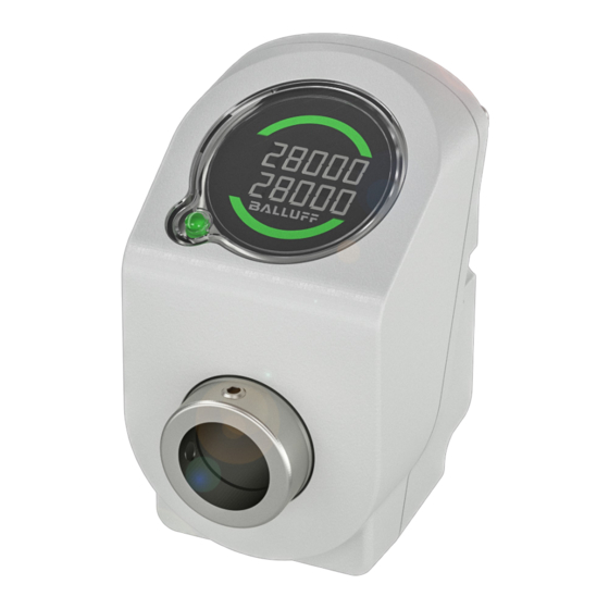
Blau statisch Es muss eine Wartung durchge- führt werden. Richtungsindikator Tab. 4-1: Orientierungs- Für weitere Signale siehe Dokument IO-Link-Konfi- indikator guration unter www.balluff.com auf der Produkt- seite. Fehler aufgetreten Positionswert außerhalb des Anzeigebereichs Bild 4-3: LC-Display www.balluff.com deutsch... -
Page 12: Typenschild
Sollwerts erforderliche Richtung. Das Display kann in der Konfiguration um 180° gedreht werden. Dies zeigt der jeweils aktive Orientierungsindikator in Form eines Pfeils nach oben und der lesbare Balluff Schriftzug an. Unter- oder überschreitet der Positionswert den Anzeige- bereich (−199999…+999999), wird Full in der entspre- chenden Zeile angezeigt. -
Page 13: Einbau Und Anschluss
Bild 5-4: Gewindestifte anziehen Einbau Abmessungen siehe Bild 4-1 auf Seite 8. Halter Gewinde- Zylinderstift Die Positionsanzeige wie folgt einbauen: stifte (2×) 1. Zylinderstift in die ausgewählte Bohrung einpressen. Welle Bild 5-5: Einbau in Schnittdarstellung Bild 5-2: Zylinderstift einpressen www.balluff.com deutsch... -
Page 14: Elektrischer Anschluss
BDG D_ _60-H020-NUS01-1318-0000-S4L4 Digitale Positionsanzeige Einbau und Anschluss (Fortsetzung) Elektrischer Anschluss Schirmung und Kabelverlegung Zur Gewährleistung der elektromagnetischen Verträglich- ► Nach dem Einbau über eine Steckverbindung elekt- keit (EMV) sind folgende Hinweise zu beachten: risch anschließen. – Beim Verlegen des Kabels zwischen Sensor, Steuerung und Stromversorgung ist die Nähe von Starkstromlei- tungen wegen der Einkopplung von Störungen zu meiden. -
Page 15: Inbetriebnahme Und Betrieb
– Bei Funktionsstörungen das BDG außer Betrieb neh- men. – Anlage gegen unbefugte Benutzung sichern. – Befestigung prüfen und ggf. nachziehen. Reinigung Alle für den Werkstoff geeigneten Reinigungsmittel dürfen verwendet werden. Wartung Das Produkt ist wartungsfrei. www.balluff.com deutsch... -
Page 16: Schnittstelle
BDG D_ _60-H020-NUS01-1318-0000-S4L4 Digitale Positionsanzeige Schnittstelle Das IO-Link-Gerät unterstützt die in diesem Kapitel aufge- führten Funktionen. Für weitere Informationen siehe Dokument IO- Link-Konfiguration unter www.balluff.com auf der Produktseite. Primäre Funktionen – Identifikation (Identification) – Geräteerkennung (Device Discovery) – Messprofile (Measurement Profiles) –... -
Page 17: Störungen, Reparatur, Demontage Und Entsorgung
Positionsinformation. keine numerische Anzeige überprüfen Tab. 8-1: Störungsbehebung Reparatur Reparaturen am Produkt dürfen nur von Balluff durchge- führt werden. Sollte das Produkt defekt sein, nehmen Sie Kontakt mit unserem Service-Center auf. Demontage Die Demontage erfolgt in umgekehrter Reihenfolge zur Montage. - Page 18 Die Angaben sind typische Werte bei 24 V DC und Raum- Elektrischer Anschluss temperatur. Der Sensor ist nach Ablauf der Einschaltverzögerung Anschluss Stecker M12x1 betriebsbereit. Anzahl Pins Weitere Daten finden Sie unter www.balluff.com Ausgang/Schnittstelle auf der Produktseite. Ausgang Pin 4 IO-Link Ausgang Pin 2 Schaltausgang PNP/ Allgemeine Merkmale...
- Page 19 Um die Washdown-Anforderungen erfüllen zu kön- nen, sind Kabel und Anschlussleitungen mit entsprechender Zulassung erforderlich. ► Mit nachfolgendem Typenschlüsselbeispiel prüfen, ob das gewähltes Balluff Zubehör für diesen Einsatz geeignet ist: BCC S4_5-_ _ _ _-_A-_ _ _-Y_8_ _ _-_ _ _-C009 www.balluff.com...
- Page 20 BDG D_ _60-H020-NUS01-1318-0000-S4L4 Digitale Positionsanzeige Typenschlüssel BDG DA160-H020-NUS01-1318-0000-S4L4 Anzeigentyp: A0 = ohne numerische Anzeige A1 = mit numerischer Anzeige Gehäusebreite: 60 = 60 mm Wellentyp: H0 = Hohlwelle Wellendurchmesser: 20 = 20 mm Schnittstellen Kategorie: digital absolut, bidirektional Schnittstelle: IO-Link Schnittstellenprofil: S0 = Smart Sensor Profil Edition 2 (SSP 2) Versorgungsspannung: 10…30 V DC Auflösung:...
- Page 21 BDG D_ _60-H020-NUS01-1318-0000-S4L4 User’s Guide english...
- Page 22 www.balluff.com...
- Page 23 4.2.1 Status LED 4.2.2 LC display Part label Installation and connection Preparing for installation Installation Electrical connection Shielding and cable routing Startup and operation Startup Operation Operating notes Cleaning Maintenance Interface Malfunctions, repair, disassembly and disposal Troubleshooting Repair Disassembly Disposal www.balluff.com english...
- Page 24 BDG D_ _60-H020-NUS01-1318-0000-S4L4 Digital position indicator Technical Data General Features Ambient conditions Measuring range Electrical data Electrical connection Output / Interface Materials Mechanical features Approvals and markings Accessories 10.1 Reducing sleeve 14 mm (BAM AD-DG-023-D14/D20-5-01) 10.2 Supply cable, preassembled with straight M12 plug Type code english...
-
Page 25: About This Guide
Other applicable documents Additional information about this product can be found at Used Technical Terms and Abbreviations www.balluff.com on the product page, e.g. in the following documents: Standard Input Output – Data sheet –... -
Page 26: Safety Notes
Flawless function in accordance with the specifications in the technical data is ensured only when using suitable original Balluff accessories. Use of any other components will void the warranty. Non-approved use is not permitted and will result in the loss of warranty and liability claims against the manufacturer. -
Page 27: Scope Of Supply, Transport And Storage
2 set screws – 1 cylindrical pin – Assembly instructions Transport ► Transport product to location of use in original packaging. Storage conditions ► Store product in original packaging. ► Observe ambient conditions (see Ambient conditions on page 16). www.balluff.com english... -
Page 28: Product Description
Without an external supply, the display unit (display and LED) is switched off. This device supports condition monitoring functions. For details, see document IO-Link configuration under www.balluff.com on the product page. english... -
Page 29: Display Elements
IO-Link master) Blue, static Maintenance must be performed. Directional indicator Tab. 4-1: Orientation indicator For further signals, see document on IO-Link configuration under www.balluff.com on the product page. Error occurred Position value outside the display range Fig. 4-3: LC display www.balluff.com... -
Page 30: Part Label
If the position value falls below or exceeds the display range (−199999…+999999), Full is displayed in the corresponding line. This does not result in any falsification of the determined measured value. For changeable parameters, see document IO-Link configuration under www.balluff.com on Order code the product page. Serial number Type Fig. -
Page 31: Installation And Connection
For dimensions, see Fig. 4-1 on page 8. Holder Set screws Cylindrical pin Install the position indicator as follows: (2×) 1. Press the cylindrical pin into the selected hole. Shaft Fig. 5-5: Installation in sectional view Fig. 5-2: Press in cylindrical pin www.balluff.com english... -
Page 32: Electrical Connection
BDG D_ _60-H020-NUS01-1318-0000-S4L4 Digital position indicator Installation and connection (continued) Electrical connection Shielding and cable routing To ensure electromagnetic compatibility (EMC), observe ► After installation, connect to power via plug connection. the following: – When ducting the cable between the sensor, controller, and power supply, it is important to avoid going near high voltage cables due to interferences. -
Page 33: Startup And Operation
Take the BDG out of operation whenever there is a malfunction. – Secure the system against unauthorized use. – Check fasteners and retighten if needed. Cleaning All cleaning agents suitable for the material may be used. Maintenance The product is maintenance-free. www.balluff.com english... -
Page 34: Interface
BDG D_ _60-H020-NUS01-1318-0000-S4L4 Digital position indicator Interface The IO-Link device supports the functions listed in this chapter. For further information, see document IO-Link configuration under www.balluff.com on the product page. Primary Functions – Identification – Device Discovery – Measurement Profiles –... -
Page 35: Malfunctions, Repair, Disassembly And Disposal
Tab. 8-1: Troubleshooting Repair Repairs to the product may only be performed by Balluff. If the product is defective, contact our Service Center. Disassembly Disassembly is performed in reverse order to assembly. 1. Loosen set screws. - Page 36 The sensor is ready for operation after the switch-on delay Connection Plug M12x1 has elapsed. Number of pins Further data can be found at www.balluff.com Output / Interface on the product page. Output pin 4 IO-Link Output pin 2 Switching output PNP/...
- Page 37 ► Use the following type code example to check whether the selected Balluff accessory is suitable for this application: BCC S4_5-_ _ _ _-_A-_ _ _-Y_8_ _ _-_ _ _-C009 www.balluff.com...
- Page 38 BDG D_ _60-H020-NUS01-1318-0000-S4L4 Digital position indicator Type code BDG DA160-H020-NUS01-1318-0000-S4L4 Display type: A0 = Without numerical display A1 = With numerical display Housing width: 60 = 60 mm Shaft type: H0 = Hollow shaft Shaft diameter: 20 = 20 mm Interfaces category: Digital absolute, bidirectional Interface: IO-Link...
- Page 39 BDG D_ _60-H020-NUS01-1318-0000-S4L4 Notice d’utilisation français...
- Page 40 www.balluff.com...
- Page 41 Plaque signalétique Montage et raccordement Préparation du montage Montage Raccordement électrique Blindage et pose des câbles Mise en service et fonctionnement Mise en service Fonctionnement Conseils d’utilisation Nettoyage Maintenance Interface Défauts, réparation, démontage et élimination Dépannage Réparation Démontage Élimination www.balluff.com français...
- Page 42 BDG D_ _60-H020-NUS01-1318-0000-S4L4 Affichage de position numérique Caractéristiques techniques Caractéristiques générales Conditions ambiantes Plage de mesure Caractéristiques électriques Raccordement électrique Sortie / interface Matériau Caractéristiques mécaniques Homologations et certifications Accessoires 10.1 Douille de réduction 14 mm (BAM AD-DG-023-D14/D20-5-01) 10.2 Câble d’alimentation, préconfectionné avec connecteur mâle M12 droit 17 Code de type français...
-
Page 43: À Propos De Cette Notice
Autres documents de référence Vous trouverez des informations complémentaires Standard Input Output (Entrée/sortie standard) concernant ce produit sur la page produit du site www.balluff.com, p. ex. dans les documents suivants : Illustrations – Fiche technique Dans la présence notice, les illustrations représentent la –... -
Page 44: Consignes De Sécurité
Son bon fonctionnement, conformément aux indications figurant dans les caractéristiques techniques, n’est garanti qu’avec les accessoires d’origine Balluff appropriés ; l’utilisation d’autres composants entraîne la nullité de la garantie. Toute utilisation inappropriée est interdite et entraîne l’annulation de la garantie et de la responsabilité... -
Page 45: Fourniture, Transport Et Stockage
1 goupille cylindrique – Notice de montage Transport ► Transporter le produit dans son emballage d’origine jusqu’au lieu d’utilisation. Conditions de stockage ► Stocker le produit dans son emballage d’origine. ► Respecter les conditions ambiantes (voir Conditions ambiantes, page 16). www.balluff.com français... -
Page 46: Description Du Produit
En l’absence d’alimentation externe, l’unité d’affichage (afficheur et LED) est désactivée. Cet appareil supporte les fonctions de Condition Monitoring (contrôle d’état). Pour les détails, voir le document Configuration IO-Link sous www.balluff.com, sur la page produit. français... -
Page 47: Éléments D'affichage
Indicateur Tab. 4-1 : LED d’orientation Pour d’autres signaux, voir le document Configuration IO-Link sur la page produit du site Erreur survenue www.balluff.com. Valeur de position en dehors de la plage d’affichage Fig. 4-3 : Afficheur à cristaux liquides www.balluff.com... -
Page 48: Plaque Signalétique
L’afficheur peut être tourné de 180° dans la configuration. Ceci est indiqué par l’indicateur d’orientation actif sous la forme d’une flèche pointant vers le haut et l’inscription Balluff lisible. Lorsque la valeur de position dépasse par défaut ou par excès la plage d’affichage (−199999…+999999), la mention Full est affichée dans la ligne correspondante. -
Page 49: Montage Et Raccordement
Dimensions, voir Fig. 4-1, page 8. Tiges Goupille filetées (2×) cylindrique Monter l’affichage de position comme suit : 1. Engager la goupille cylindrique dans le trou choisi. Arbre Fig. 5-5 : Montage vu en coupe Fig. 5-2 : Engagement de la goupille cylindrique www.balluff.com français... -
Page 50: Raccordement Électrique
BDG D_ _60-H020-NUS01-1318-0000-S4L4 Affichage de position numérique Montage et raccordement (suite) Raccordement électrique Blindage et pose des câbles Pour garantir la compatibilité électromagnétique (CEM), les ► Après le montage, effectuer le branchement électrique consignes suivantes doivent être respectées : sur une prise de courant. –... -
Page 51: Mise En Service Et Fonctionnement
En cas de dysfonctionnement, mettre le BDG hors service. – Protéger l’installation de toute utilisation non autorisée. – Contrôler la fixation, resserrer si nécessaire. Nettoyage Tous les produits de nettoyage appropriés pour le matériau peuvent être utilisés. Maintenance Le produit est sans entretien. www.balluff.com français... -
Page 52: Interface
BDG D_ _60-H020-NUS01-1318-0000-S4L4 Affichage de position numérique Interface L’appareil IO-Link supporte les fonctions mentionnées dans ce chapitre. Pour plus d’informations, voir le document Configuration IO-Link sous www.balluff.com, sur la page produit. Fonctions primaires – Identification (Identification) – Détection de l’appareil (Device Discovery) –... -
Page 53: Défauts, Réparation, Démontage Et Élimination
► Avant de réenclencher l’installation ou l’élément de machine, s’assurer que la goupille cylindrique est présente et n’est pas tombée dans l’installation. Élimination ► Pour l’élimination des déchets, se conformer aux dispositions nationales. Vous trouverez des informations complémentaires sous www.balluff.com, sur la page produit. www.balluff.com français... - Page 54 Après l’écoulement de la temporisation à l’enclenchement, Raccordement Connecteur mâle M12x1 le capteur est opérationnel. Nombre de broches Vous trouverez des informations supplémentaires Sortie / interface sous www.balluff.com, sur la page produit. Sortie broche 4 IO-Link Caractéristiques générales Sortie broche 2 Sortie de commutation PNP/NPN configurable Résolution...
- Page 55 Affichage de position numérique Accessoires Les accessoires ne sont pas compris dans le matériel livré et doivent être commandés séparément. Vous trouverez les accessoires conseillés sous www.balluff.com, sur la page produit. 10.1 Douille de réduction 14 mm (BAM AD-DG-023-D14/D20-5-01) Symbolisation commerciale : BAM03KE Fig.
- Page 56 BDG D_ _60-H020-NUS01-1318-0000-S4L4 Affichage de position numérique Code de type BDG DA160-H020-NUS01-1318-0000-S4L4 Type d’affichage : A0 = sans affichage numérique A1 = avec affichage numérique Largeur du boîtier : 60 = 60 mm Type d’arbre : H0 = Arbre creux Diamètre de l’arbre : 20 = 20 mm Catégorie d’interface : numérique absolue, bidirectionnelle Interface :...
- Page 57 BDG D_ _60-H020-NUS01-1318-0000-S4L4 Manuale d’uso italiano...
- Page 58 www.balluff.com...
- Page 59 Montaggio e collegamento Preparazione del montaggio Montaggio Collegamento elettrico Schermatura e posa dei cavi Messa in funzione e funzionamento Messa in funzione Funzionamento Avvertenze per il funzionamento Pulizia Manutenzione Interfaccia Anomalie, riparazione, smontaggio e smaltimento Eliminazione dell’anomalia Riparazione Smontaggio Smaltimento www.balluff.com italiano...
- Page 60 BDG D_ _60-H020-NUS01-1318-0000-S4L4 Indicatore di posizione digitale Dati tecnici Caratteristiche generali Condizioni ambientali Campo di misura Caratteristiche elettriche Collegamento elettrico Uscita/Interfaccia Materiale Caratteristiche meccaniche Autorizzazioni e contrassegni Accessori 10.1 Manicotto di riduzione 14 mm (BAM AD-DG-023-D14/D20-5-01) 10.2 Cavo di alimentazione, confezionato con connettore M12 dritto Legenda codici di identificazione italiano...
-
Page 61: Informazioni Sulle Presenti Istruzioni
Documenti di riferimento Espressioni tecniche ed abbreviazioni Ulteriori informazioni sul presente prodotto sono disponibili utilizzate all’indirizzo www.balluff.com, pagina Prodotti, ad es. nei seguenti documenti: Standard Input/Output – Scheda tecnica –... -
Page 62: Avvertenze Di Sicurezza
Il funzionamento corretto secondo le indicazioni fornite nei dati tecnici viene garantito soltanto con accessori originali Balluff di tipo idoneo. L’utilizzo di altri componenti comporta la decadenza della garanzia. L’uso improprio non è consentito e determina la decadenza di qualsiasi garanzia o responsabilità... -
Page 63: Fornitura, Trasporto E Magazzinaggio
1 perno cilindrico – Istruzioni di montaggio Trasporto ► Trasportare il prodotto nella confezione originale fino al luogo di utilizzo. Condizioni di magazzinaggio ► Conservare il prodotto nella confezione originale. ► Attenersi alle condizioni ambientali (vedere Condizioni ambientali a pag. 16). www.balluff.com italiano... -
Page 64: Descrizione Del Prodotto
Senza l’alimentazione sterna, l’unità di visualizzazione (display e LED) è spenta. Il presente apparecchio supporta funzioni di Condition Monitoring. Per ulteriori dettagli, vedere documento Configurazione IO-Link, all’indirizzo www.balluff.com, pagina Prodotti. italiano... -
Page 65: Elementi Di Visualizzazione
È necessario un intervento di Indicatore di manutenzione. orientamento Tab. 4-1: Si è verificato un Per ulteriori segnali, vedere documento errore Configurazione IO-Link, all’indirizzo www.balluff.com, pagina Prodotti. Valore di posizione al di fuori dell’intervallo di visualizzazione Fig. 4-3: Display LCD www.balluff.com italiano... -
Page 66: Targhetta Di Identificazione
Il display può essere ruotato di 180° nella configurazione. Questo riporta il rispettivo indicatore di orientamento attivo sotto forma di una freccia verso l’alto e la scritta Balluff leggibile. Se il valore di posizione scende al di sotto o supera l’intervallo di visualizzazione (−199999…+999999), nella... -
Page 67: Montaggio E Collegamento
Per le dimensioni, vedere Fig. 4-1 a pag. 8. Supporto Montare l’indicatore di posizione come segue: Perni filettati Perno cilindrico 1. Pressare il perno cilindrico nel foro selezionato. (2 pz.) Albero Fig. 5-5: Montaggio nella vista in sezione Fig. 5-2: Pressare il perno cilindrico www.balluff.com italiano... -
Page 68: Collegamento Elettrico
BDG D_ _60-H020-NUS01-1318-0000-S4L4 Indicatore di posizione digitale Montaggio e collegamento (continua) Collegamento elettrico Schermatura e posa dei cavi Per garantire la compatibilità elettromagnetica (EMC) è ► Dopo il montaggio, collegare elettricamente utilizzando necessario rispettare le seguenti avvertenze: un connettore. – Nella posa del cavo tra sensore, unità... -
Page 69: Messa In Funzione E Funzionamento
In caso di anomalie di funzionamento disattivare il BDG. – Proteggere l’impianto dagli utilizzi non autorizzati. – Controllare il fissaggio e, all’occorrenza, riserrare. Pulizia Possono essere utilizzati tutti i detergenti adatti al materiale. Manutenzione Il prodotto è esente da manutenzione. www.balluff.com italiano... -
Page 70: Interfaccia
BDG D_ _60-H020-NUS01-1318-0000-S4L4 Indicatore di posizione digitale Interfaccia L’apparecchio IO-Link supporta le funzioni riportate nel presente capitolo. Per ulteriori informazioni, vedere documento Configurazione IO-Link, all’indirizzo www.balluff.com, pagina Prodotti. Funzioni primarie – Identificazione (Identification) – Riconoscimento apparecchio (Device Discovery) – Profili di misurazione (Measurement Profiles) –... -
Page 71: Anomalie, Riparazione, Smontaggio E Smaltimento
Tab. 8-1: Eliminazione dell’anomalia Riparazione Gli interventi di riparazione sul prodotto andranno effettuati esclusivamente da Balluff. Qualora il prodotto dovesse presentare difetti, contattare il nostro Service Center. Smontaggio Lo smontaggio avviene in ordine inverso al montaggio. - Page 72 Il sensore è pronto per il funzionamento una volta trascorso Collegamento Connettore M12x1 il ritardo di inserimento. Numero di pin Ulteriori dati sono disponibili all’indirizzo Uscita/Interfaccia www.balluff.com, pagina Prodotti. Uscita pin 4 IO-Link Uscita pin 2 Uscita commutata PNP/ Caratteristiche generali NPN configurabile...
- Page 73 ► Con il seguente esempio di legenda dei codici di identificazione controllare se l’accessorio Balluff scelto è adatto per questo impiego: BCC S4_5-_ _ _ _-_A-_ _ _-Y_8_ _ _-_ _ _-C009 www.balluff.com italiano...
- Page 74 BDG D_ _60-H020-NUS01-1318-0000-S4L4 Indicatore di posizione digitale Legenda codici di identificazione BDG DA160-H020-NUS01-1318-0000-S4L4 Tipo di indicazione: A0 = senza indicazione numerica A1 = con indicazione numerica Larghezza corpo: 60 = 60 mm Tipo albero: H0 = Albero cavo Diametro albero: 20 = 20 mm Categoria interfacce: digitale assoluta, bidirezionale Interfaccia:...
- Page 75 BDG D_ _60-H020-NUS01-1318-0000-S4L4 Instrukcja obsługi polski...
- Page 76 www.balluff.com...
- Page 77 4.2.2 Wyświetlacz ciekłokrystaliczny Tabliczka znamionowa Montaż i podłączenie Przygotowanie do montażu Montaż Podłączenie elektryczne Ekran i ułożenie przewodu Uruchomienie i eksploatacja Uruchomienie Eksploatacja Wskazówki dotyczące eksploatacji Czyszczenie Konserwacja Interfejs Usterki, naprawa, demontaż i utylizacja Usuwanie usterek Naprawa Demontaż Utylizacja www.balluff.com polski...
- Page 78 BDG D_ _60-H020-NUS01-1318-0000-S4L4 Cyfrowy przetwornik położenia Dane techniczne Ogólne właściwości Warunki otoczenia Zakres pomiarowy Właściwości elektryczne Podłączenie elektryczne Wyjście/interfejs antypoślizgowy Właściwości mechaniczne Certyfikaty i oznaczenia Wyposażenie 10.1 Tuleja redukcyjna 14 mm (BAM AD-DG-023-D14/D20-5-01) 10.2 Kabel zasilający, prefabrykowany z prostą wtyczką M12 Oznaczenie typu polski...
-
Page 79: Informacje O Instrukcji
śmierci lub poważnych obrażeń cielesnych. Dodatkowo obowiązujące dokumenty Dalsze informacje dotyczące tego produktu znajdziesz na www.balluff.com na stronie produktu np. w Zastosowane pojęcia i skróty następujących dokumentach: Standard Input Output –... -
Page 80: Zasady Bezpieczeństwa
Przewidziany jest do zastosowań przemysłowych. Prawidłowe działanie zgodne z danymi technicznymi gwarantowane jest wyłącznie z odpowiednim, oryginalnym wyposażeniem Balluff. Stosowanie innych elementów powoduje wykluczenie odpowiedzialności. Użytkowanie niezgodne z przeznaczeniem jest niedozwolone i prowadzi do utraty roszczeń gwarancyjnych i roszczeń z tytułu odpowiedzialności w stosunku do producenta. -
Page 81: Zakres Dostawy, Transport I Przechowywanie
– 2 śruby bezłbowe – 1 sworzeń cylindryczny – Instrukcja montażu Transport ► Przetransportować produkt w oryginalnym opakowaniu do miejsca zastosowania. Warunki przechowywania ► Przechowywać produkt w oryginalnym opakowaniu. ► Przestrzegać warunków otoczenia (patrz Warunki otoczenia na stronie 16). www.balluff.com polski... -
Page 82: Opis Produktu
Bez zewnętrznego zasilania wyświetlacz (wyświetlacz i LED) jest wyłączony. To urządzenie obsługuje funkcje Condition- Monitoring. W celu uzyskania szczegółowych informacji patrz dokument dot. konfiguracji IO-Link na www.balluff.com na stronie produktu. polski... -
Page 83: Elementy Wskazujące
Konieczne wykonanie czynności ciągłym w kolorze konserwacyjnych. niebieskim Wystąpił błąd Tab. 4-1: W celu uzyskania informacji o dalszych sygnałach Wartość położenia poza zakresem patrz dokument dot. konfiguracji IO-Link na wskazania www.balluff.com na stronie produktu. Rys. 4-3: Wyświetlacz ciekłokrystaliczny www.balluff.com polski... -
Page 84: Tabliczka Znamionowa
W celu konfiguracji wyświetlacz może być obrócony o 180°. Wskazuje on aktywny wskaźnik orientacji w postaci strzałki skierowanej ku górze oraz czytelny napis Balluff. Jeżeli wartość pozycji spadnie poniżej lub przekroczy zakres wskazania (-199999…+999999), w odpowiednim wierszu wyświetlony zostanie komunikat Full. -
Page 85: Montaż I Podłączenie
Wymiary patrz Rys. 4-1 na stronie 8. Uchwyt Śruby Przetwornik położenia należy zainstalować w następujący bezłbowe Sworzeń sposób: (2×) cylindryczny 1. Wcisnąć sworzeń cylindryczny w wybrany otwór. Wałek Rys. 5-5: Montaż w widoku przekrojowym Rys. 5-2: Wciśnięcie sworznia cylindrycznego www.balluff.com polski... -
Page 86: Podłączenie Elektryczne
BDG D_ _60-H020-NUS01-1318-0000-S4L4 Cyfrowy przetwornik położenia Montaż i podłączenie (cd.) Podłączenie elektryczne Ekran i ułożenie przewodu W celu zagwarantowania kompatybilności ► Po zamontowaniu podłączyć elektrycznie za pomocą elektromagnetycznej (EMC) należy przestrzegać złącza wtykowego. następujących wskazówek: – Przy układaniu kabla pomiędzy czujnikiem, sterownikiem i zasilaniem należy unikać... -
Page 87: Uruchomienie I Eksploatacja
– W razie usterek w działaniu wyłączyć BDG. – Zabezpieczyć urządzenie przed użyciem przez osoby niepowołane. – Sprawdzić mocowanie, w razie potrzeby dociągnąć. Czyszczenie Można stosować wszystkie środki czyszczące odpowiednie dla danego materiału. Konserwacja Produkt jest bezobsługowy. www.balluff.com polski... -
Page 88: Interfejs
BDG D_ _60-H020-NUS01-1318-0000-S4L4 Cyfrowy przetwornik położenia Interfejs Urządzenie IO-Link obsługuje funkcje wymienione w tym rozdziale. W celu uzyskania dalszych informacji patrz dokument dot. konfiguracji IO-Link na www.balluff.com na stronie produktu. Funkcje podstawowe – Identyfikacja (Identification) – Detekcja urządzeń (Device Discovery) –... -
Page 89: Usterki, Naprawa, Demontaż I Utylizacja
► Przed ponownym włączeniem urządzenia lub części maszyny należy upewnić się, że sworzeń cylindryczny jest obecny i nie wpadł do urządzenia. Utylizacja ► Przestrzegać krajowych przepisów dotyczących utylizacji. Dalsze informacje znajdziesz na www.balluff.com na stronie produktu. www.balluff.com polski... - Page 90 Dane dotyczą typowych wartości przy 24 V DC i Podłączenie elektryczne temperaturze pokojowej. Czujnik jest gotowy do pracy po upływie czasu opóźnienia Złącze Wtyczka M12x1 włączania. Liczba pinów Dalsze dane znajdziesz na www.balluff.com na Wyjście/interfejs stronie produktu. Wyjście pin 4 IO-Link Wyjście pin 2 Wyjście przełączające Ogólne właściwości PNP/NPN z możliwością...
- Page 91 ► Za pomocą następującego przykładu kodu produktu należy sprawdzić, czy wybrane wyposażenie Balluff jest odpowiednie do tego zastosowania BCC S4_5-_ _ _ _-_A-_ _ _-Y_8_ _ _-_ _ _-C009 www.balluff.com polski...
- Page 92 BDG D_ _60-H020-NUS01-1318-0000-S4L4 Cyfrowy przetwornik położenia Oznaczenie typu BDG DA160-H020-NUS01-1318-0000-S4L4 Typ wyświetlacza: A0 = bez wyświetlacza numerycznego A1 = z wyświetlaczem numerycznym Szerokość obudowy: 60 = 60 mm Typ wałka: H0 = Wałek drążony Średnica wałka: 20 = 20 mm Kategoria interfejsu: cyfrowy absolutny, dwukierunkowy Interfejs: IO-Link...
- Page 94 Americas Service Center Asia Pacific Service Center Poland Greater China Balluff Sp. z o.o. Balluff Inc. Balluff Automation (Shanghai) Co., Ltd. Ul. Graniczna 21A 8125 Holton Drive No. 800 Chengshan Rd, 8F, Building A, 54-516 Wrocław Florence, KY 41042 Yunding International Commercial Plaza...
Need help?
Do you have a question about the BDG D 60-H020-NUS01-1318-0000-S4L4 Series and is the answer not in the manual?
Questions and answers