Balluff Micropulse BTL5-A series User Manual
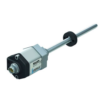
Micropulse linear transducer
analog output-rod style
Hide thumbs
Also See for Micropulse BTL5-A series:
- User manual (80 pages) ,
- User manual (8 pages) ,
- User manual (12 pages)

Subscribe to Our Youtube Channel
Related Manuals for Balluff Micropulse BTL5-A series


Summary of Contents for Balluff Micropulse BTL5-A series
- Page 1 Sensors Worldwide Technical Description / User’s Guide BTL5-A/C/E/G__-M____-B/Z-S32/KA__ Micropulse Linear Transducer Analog Output-Rod Style ™...
- Page 2 BTL5-A/C/E/G__-M____-B/Z-S32/KA__ Micropulse Linear Position Transducer Analog Output-Rod Style ™ 1-800-543-8390 • WWW.BALLUFF.COM...
- Page 3 11 12 13 14 15 16 17 18 19 20 21 22 Rod Style B T L - M 0 3 0 5 - Z - S 3 2 Balluff - Linear Transducer Generation 5 Output Type Compact, 0 to 10Vdc bolt-in...
-
Page 4: Table Of Contents
US Patent 5 923 164 DATech for Testing Electromagnetic Apparatus and Method for Compatibility, has confirmed that S u r g e Balluff products meet the EMC Automatically Tuning the EN 61000-4-5 Severity level 2 Gain of an Amplifier requirements of the following Generic... -
Page 5: Function And Characteristics
(Fig. 3-1). Note the recommended for magnetizable materials a = Spacer made of non-magnetizable distance of the trans- materials ducer and cylinder from for non-magnetizable materials b = Magnet strong, external magnetic fields. Fig. 3-1: Mounting WWW.BALLUFF.COM • 1-800-543-8390... -
Page 6: Transducer, Installation
3/4"-16UNF thread for mounting. The sealing is carried out with the O-ring supplied at the flange facing. Threaded hole 3/4"-16UNF per SAE J475 O-ring 15.3 × 2.4 Fig. 3-3: Threaded hole for mounting the BTL with O-ring 1-800-543-8390 • WWW.BALLUFF.COM... -
Page 7: Magnets, Installation
Fig. 3-1. is connected to the housing in the electromagnetic compatibility PG fitting. (EMC) which Balluff warrants with the CE Mark, the following The cable shield must be grounded on instructions must be strictly the control side, i.e., connected to the BTL-P-1013-4R followed. -
Page 8: Startup
V and 4 to 20 mA outputs. For all within the maximum and after 10 minutes. other versions the corresponding minimum possible output values values can be found in the value table (value table 7-1 on page 8). 7-1 on page 8. 1-800-543-8390 • WWW.BALLUFF.COM... -
Page 9: Selecting Calibration Mode
See Section 10: Online Manual adjust setting mode This method allows you to set a new start and/or end value. This may be useful if the magnet can not be brought to the null or end point of the transducer. WWW.BALLUFF.COM • 1-800-543-8390... -
Page 10: Teach-In Mode
) t l 0 – 0 – ) t l 1 – 1 – 1 – ) t l 5 – 5 – 5 – > > > < < Table 7-1: Value table for teach-in and manual adjust 1-800-543-8390 • WWW.BALLUFF.COM... -
Page 11: Manual Adjust Mode
>6 s Error value value is displayed. Then press one of Current the buttons briefly (<1 s) to disable <1 s 10.50 3.60 both buttons. position value Check your settings carefully 9.00 19.00 before starting up the system. WWW.BALLUFF.COM • 1-800-543-8390... -
Page 12: Resetting All Values (Reset)
6 s. The Null value is displayed, and the reset has taken place. 4. Release buttons. The current position value is displayed and the buttons are again deacti- vated. The transducer is ready for new calibration. 1-800-543-8390 • WWW.BALLUFF.COM... -
Page 13: Online-Setting Mode
15 s. The buttons are again position value disabled. Another adjustment procedure can be carried out. new start value The values shown here are examples only. WWW.BALLUFF.COM • 1-800-543-8390... -
Page 14: Technical Data
BTL5-_2... DC ±14.7 to ±15.3 V aluminum Individual specifications as per Current draw < 150 mA Operating temp. –40 °C to +85 °C Balluff factory standard Inrush < 3 A/0.5 ms Magnets BTL5-P-4500-1 Polarity reversal protection built-in Overvoltage protection (Electromagnet) - Page 15 No. 99-5672-78-08 (Binder part no.) BTL-P-1012-4R straight BKS-S 32M-00 No. 99-5672-19-08 (Binder part no.) Fig. 4-3: Connector (optional) Fig. 3-4: Magnet (optional) = Button 2 = Button 1 gray blue Fig. 6-1: Calibration device (shown on transducer) WWW.BALLUFF.COM • 1-800-543-8390...
- Page 16 Phone: (905) 816-1494 Toll-free: 1-800-927-9654 Fax: (905) 816-1411 Web: www.balluff.ca E-mail: balluff.canada@balluff.ca Mexico Balluff de Mexico S.A. de C.V Fray Pedro de Gante 25 P.B. Col. Cimatario Queretaro, QRO 76030 Phone: (++52 442) 212-4882, 224-3583, 224-3171 Fax: (++52 442) 214-0536...
Need help?
Do you have a question about the Micropulse BTL5-A series and is the answer not in the manual?
Questions and answers