Balluff BTL7-S5 B-M Series User Manual
Hide thumbs
Also See for BTL7-S5 B-M Series:
- User manual (210 pages) ,
- Condensed manual (16 pages) ,
- Condensed manual (16 pages)

Related Manuals for Balluff BTL7-S5 B-M Series


Summary of Contents for Balluff BTL7-S5 B-M Series
- Page 1 BTL7-S5 _ _ (B)-M _ _ _ _ -A/B/Y/Z(8)-S32/S115/S140/S147/ _ _ _ _ User's Guide english...
- Page 2 www.balluff.com...
-
Page 3: Table Of Contents
Synchronous and asynchronous operation Configuration using the Micropulse Configuration Tool (only for BTL7-S510(B)-…) 17 Micropulse Configuration Tool (software) Connecting the USB communication box Configuration options Technical data Accuracy Ambient conditions Supply voltage Output Dimensions, weights Update rate and clock frequency www.balluff.com english... - Page 4 BTL7-S5 _ _ (B)-M _ _ _ _ -A/B/Y/Z(8)-S32/S115/S140/S147/KA _ _ /FA _ _ Micropulse Transducer - Rod Style Accessories Magnets Mounting nut Connectors and cables 9.3.1 BKS-S32/S33M-00, freely configurable 9.3.2 BKS-S232/S233-PU-_ _, preassembled 9.3.3 BKS-S115/S116-PU-_ _, preassembled 9.3.4 BKS-S140-23-00, freely configurable 9.3.5 BKS-S147/S148M-00, freely configurable USB communication box Type code breakdown Appendix...
-
Page 5: Notes To The User
The magnets are available in various models declaration of conformity. and must be ordered separately. Abbreviations Approvals and markings Synchronous Serial Interface UL approval File no. E227256 US Patent 5 923 164 The US patent was awarded in connection with this product. Not for BTL7-…-FA_ _ www.balluff.com english... -
Page 6: Safety
The warnings used here contain various signal words and specifications in the technical data is ensured only when are structured as follows: using original BALLUFF accessories. Use of any other SIGNAL WORD components will void the warranty. Hazard type and source... -
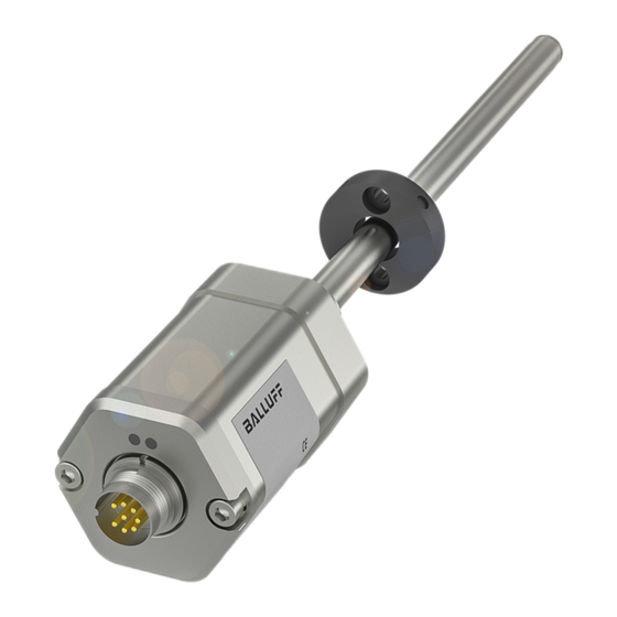
Page 7: Construction And Function
(only BTL7-S510(B)-…): – Differential position Damping zone: Area at the end of the rod that cannot be – Speed (with or without leading sign) used for measurements, but which may be passed over. – Speed difference www.balluff.com english... -
Page 8: Led Display
BTL7-S5 _ _ (B)-M _ _ _ _ -A/B/Y/Z(8)-S32/S115/S140/S147/KA _ _ /FA _ _ Micropulse Transducer - Rod Style Construction and function (continued) Behavior of LED 1 and the error value through the entire LED display range: LED 1 LED 2 Magnet missing ≈ 5 mm Null point End point Fig. -
Page 9: Installation And Connection
Fig. 4-4: Mounting hole 3/4"-16UNF per SAE J475 O-ring 15.3x2.4 Rod diameter Bore diameter D2 10.2 mm At least 13 mm Magnet: Various magnets are available for the BTL7 8 mm At least 11 mm transducer (see Accessories on page 21). Tab. 4-1: Bore diameter if installed in a hydraulic cylinder www.balluff.com english... -
Page 10: Installing The Transducer
BTL7-S5 _ _ (B)-M _ _ _ _ -A/B/Y/Z(8)-S32/S115/S140/S147/KA _ _ /FA _ _ Micropulse Transducer - Rod Style Installation and connection (continued) The sliding element can be screwed on or bonded. Installing the transducer ► Secure the screws so they cannot be loosened or lost. ►... -
Page 11: Electrical Connection
Communication line Tab. 4-4: Connection assignment BTL7…-S140 Fig. 4-9: Pin assignment of S32 (view of connector pins of transducer), 8-pin M16 circular plug Fig. 4-11: Pin assignment of S140 (view of connector pins of transducer), 10-pin circular plug www.balluff.com english... -
Page 12: Connector Type S147
BTL7-S5 _ _ (B)-M _ _ _ _ -A/B/Y/Z(8)-S32/S115/S140/S147/KA _ _ /FA _ _ Micropulse Transducer - Rod Style Installation and connection (continued) +Clk 4.4.4 Connector type S147 –Clk BTL7 standard +Data –Data BTL7-S5_ _-…-S147 BTL7-S5_ _B-…-S147 Evaluation BTL7…- +24 V –Data cable controller +Data Fig. 4-13: Connection example for BTL7-S…-cable 24 V DC with +Clk evaluation/controller... -
Page 13: Startup
Operating notes – Check the function of the transducer and all associated components on a regular basis. – Take the position measuring system out of operation whenever there is a malfunction. – Secure the system against unauthorized use. www.balluff.com english... -
Page 14: Ssi Interface
BTL7-S5 _ _ (B)-M _ _ _ _ -A/B/Y/Z(8)-S32/S115/S140/S147/KA _ _ /FA _ _ Micropulse Transducer - Rod Style SSI interface Principle With the BTL7-S5_ _B-M…, position data is determined and output in a timely manner and synchronous to the SSI stands for Synchronous Serial Interface and describes external sampling period. -
Page 15: Data Formats
The t timer is started again for every additional negative edge from Clk and the T event is set internally. Data switches back to high after the time t elapsed. www.balluff.com english... -
Page 16: Synchronous And Asynchronous Operation
BTL7-S5 _ _ (B)-M _ _ _ _ -A/B/Y/Z(8)-S32/S115/S140/S147/KA _ _ /FA _ _ Micropulse Transducer - Rod Style SSI interface (continued) Synchronous and asynchronous operation Two boundary conditions must be taken into account during synchronous operation: Synchronous operation – The external sampling frequency f must be in the range A uniform and brief timing is often required for control 62.5 Hz < f < f... -
Page 17: Configuration Using The Micropulse Configuration Tool (Only For Btl7-S510(B)
The PC software and associated manual can movement from the end point to the starting point is be found in the Internet under output with a negative sign. www.balluff.com. – Speed (unsigned): Speed of the magnet, the direction of movement cannot be read. -
Page 18: Technical Data
Ambient conditions : Use in enclosed spaces and up to a height of 2000 m above sea level. Operating temperature −40°C…+85°C Individual specifications as per Balluff factory standard, resonances excluded Operating temperature for UL Max. +80°C (only BTL7…-KA…) : The transducer must be externally connected via a limited- energy circuit as defined in UL 61010-1, a low-power source as defined in... -
Page 19: Output
Weight (depends on Approx. 2 kg/m length) Housing material Aluminum Flange material Stainless steel Rod material Stainless steel Rod wall thickness For Ø 8 mm 0.9 mm For Ø 10.2 mm 2 mm Young's modulus Approx. 200 kN/mm Housing mounting via M18×1.5 or 3/4"-16UNF threads Tightening torque Max. 100 Nm www.balluff.com english... -
Page 20: Update Rate And Clock Frequency
BTL7-S5 _ _ (B)-M _ _ _ _ -A/B/Y/Z(8)-S32/S115/S140/S147/KA _ _ /FA _ _ Micropulse Transducer - Rod Style Technical data (continued) Connection to the evaluation unit The maximum sampling frequency f , at which a new The minimum sampling frequency f is 62,5 Hz. A,max A,min current value is available with each sampling, can be found in the following graphic:... -
Page 21: Accessories
– 40°C…+ 60°C BTL-P-1028-15R (special accessories for applications with a supporting rod): Weight: Approx. 68 g Housing: Aluminum BTL-P-1012-4R 120° Ø 4.3 BTL-P-1014-2R Mounting nut – Mounting nut M18×1.5: BTL-A-FK01-E-M18×1.5 – 3/4”-16UNF mounting nut: BTL-A-FK01-E-3/4”-16UNF Fig. 9-1: Magnet installation dimensions BTL-P-0814-GR-PAF www.balluff.com english... -
Page 22: Connectors And Cables
BTL7-S5 _ _ (B)-M _ _ _ _ -A/B/Y/Z(8)-S32/S115/S140/S147/KA _ _ /FA _ _ Micropulse Transducer - Rod Style Accessories (continued) Connectors and cables BKS-S233-PU-_ _ Angled connector, molded, preassembled M16, 8-pin Various cable lengths can be ordered, e.g. 9.3.1 BKS-S32/S33M-00, freely configurable BKS-S233-PU-05: Cable length 5 m BKS-S32M-00 Ø... -
Page 23: Bks-S140-23-00, Freely Configurable
Scope of delivery: USB communication box, USB cable, 2 adapter cables each approx. 0.3 m, condensed guide. BTL7-A-CB01-USB-KA For BTL7-S510(B)-… with cable connection. Scope of delivery: USB communication box, USB cable, 1 adapter cable each approx. 0.6 m, condensed guide. Fig. 9-9: Connector type BKS-S140-23-00 www.balluff.com english... -
Page 24: Type Code Breakdown
BTL7-S5 _ _ (B)-M _ _ _ _ -A/B/Y/Z(8)-S32/S115/S140/S147/KA _ _ /FA _ _ Micropulse Transducer - Rod Style Type code breakdown BTL7 standard BTL7 - S 5 0 1 B - M0500 - B - S32 Micropulse transducer SSI interface Supply voltage: 5 = 10…30 V DC Data format: 24 bit 25 bit... - Page 25 Y8 = 3/4"-16UNF thread, O-ring, rod diameter 8 mm Z8 = 3/4"-16UNF thread, O-ring, rod diameter 8 mm Electrical connection: S32 = 8-pin, M16 plug per IEC 130-9 S115 = 8-pin, M12 plug S140 = 10-pin, plug KA05 = Cable, 5 m (PUR) FA05 = Cable, 5 m (PTFE) www.balluff.com english...
-
Page 26: Appendix
BTL7-S5 _ _ (B)-M _ _ _ _ -A/B/Y/Z(8)-S32/S115/S140/S147/KA _ _ /FA _ _ Micropulse Transducer - Rod Style Appendix 11.1 Converting units of length 11.2 Product labels 1 mm = 0.0393700787 inch inches 0.03937008 0.07874016 0.11811024 Ordering code 0.15748031 Type code 0.19685039 0.23622047 Serial number 0.27559055 0.31496063 0.35433071 0.393700787 Tab. - Page 27 US Service Center CN Service Center Germany Germany China Balluff GmbH Balluff GmbH Balluff Inc. Balluff (Shanghai) trading Co., ltd. Schurwaldstrasse 9 Schurwaldstrasse 9 8125 Holton Drive Room 1006, Pujian Rd. 145. 73765 Neuhausen a.d.F. 73765 Neuhausen a.d.F. Florence, KY 41042 Shanghai, 200127, P.R.
Need help?
Do you have a question about the BTL7-S5 B-M Series and is the answer not in the manual?
Questions and answers