
Related Manuals for J-Tech Digital JTECH-4K88-EX2


Summary of Contents for J-Tech Digital JTECH-4K88-EX2
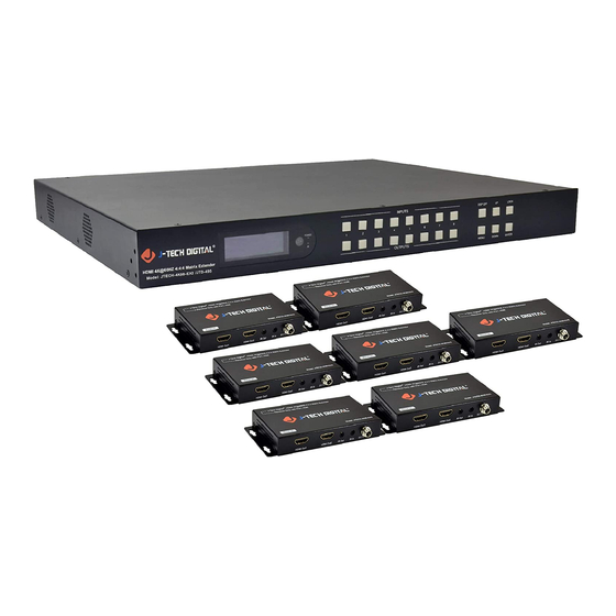
- Page 1 Website: www.jtechdigital.com Toll Free: 1-888-610-2818 Email: support@jtechdigital.com USER MANUAL J-Tech Digital® HDMI 4K@60HZ 4:4:4 Matrix Extender Model: JTECH-4K88-EX2 JTD-ID: 495...
-
Page 2: Table Of Contents
Operating Instruction Catalogue 1. Features ............................3 2. Package Contents ..........................3 3. Specifications ..........................3 4. Panel Descriptions........................... 4 4.1 Input / output channel key operation ..................5 4.2 Video switching operation ..................... 6 4.2.1 Video switch ....................... 6 4.2.2 Video Control ...................... -
Page 3: Features
Operating Instruction 1. Features Incorporate HDBaseT technology HDMI 2.0 version support 4K@60Hz YUV4:4:4, 18G, HDR10 Any one of the 8 HDMI Sources to any one of the 8 HDMI Displays 8 outputs includes 7*HDBaseT output and 1*HDMI output ... -
Page 4: Panel Descriptions
Operating Instruction 4. Panel Descriptions LCD: Showing Matrix information Input button OUT1~8 Output button IN1~8 Function button: DSP OFF; MENU; UP; DOWN; LOCK; ENTER DSP OFF : Short press output N, then press DSP OFF to turn off the output. Long press Output 8 to select all output, then press DSP OFF to turn off all the output. -
Page 5: Input / Output Channel Key Operation
Operating Instruction 4.1 Input / output channel key operation Channel Button method Any Key The first operation of the button can wake up the screen Directly press the number key, such as input channel 1, and select "1" to press (only when Input 1-8 the output port is selected, the input channel number will be valid) Directly press the number key, such as the output channel 5, select the key "5"... -
Page 6: Video Switching Operation
Operating Instruction 4.2 Video switching operation 4.2.1 Video switch The signal switch includes 8 free switching channels, which can be configured as input/output according to the requirements, forming a matrix of 1 x 8 ~ 8 x 1, which can switch any input. Signal to 1 channel output or all channel output. - Page 7 Operating Instruction Video Switch (P2) 2.Video On/Off...
- Page 8 Operating Instruction Video On/Off (P3) 4.2.3 Audio Separation The Audio Control have NINE sub menu 1. Out 1 ~ Out 8 2. Mute (Default) The specific operation is as follows: Audio interface can be set to output Audio (Analog or SPDIF), then choose Audio output or mute Operating instructions: Select "Audio"...
-
Page 9: Edid Set Mode Interface
Operating Instruction 4.3 EDID Set Mode Interface Default EDID EDID Mode can set each input’s EDID, Include: Default EDID; User EDID; Copy EDID; Copy HDBT EDID. Specific operations are as follows... -
Page 10: Setup Mode Interface
Operating Instruction EDID Setting mode (P6) 4.4 SETUP mode Interface SETUP mode can set the device’s RS-232 baud rate, DHCP, Reboot, Factory Specific operations are as follows 1. RS-232 Baud Rate setting It has 7 kinds of baud rates inside the device: 2400; 4800; 9600; 19200; 38400; 57600; 115200 Default Baud Rate is: 115200 BAUD RATE setting (P7) 2. -
Page 11: Reboot Setting
Operating Instruction DHCP setting (P8) 3. Reboot setting Reboot setting (P9) 4. Factory setting Factory setting (P10) -
Page 12: Info Mode Interface
Operating Instruction 4.5 INFO mode Interface Check the device information: IP or System information INFO mode (P11) -
Page 13: Application Diagram
Operating Instruction 5. Application Diagram... -
Page 14: Remote Control Description
Operating Instruction Remote Control Description Standby Mode Lock or Unlock the Panel Button Choose output from 1-8 Choose all the outputs. X: Turn on/off output port which you select PTP button: Mirror all inputs and outputs (Ex. Input 1 to output 1, input 2 to output 2, etc) Choose input from 1-8 Menu (back to previous option) button UP and DOWN button... -
Page 15: Command Control
Operating Instruction 8. Command Control Control software operation: The serial control software is illustrated with SSCOM32 as an example. Basic Settings: Double-click the software in the installation package to run specifically (as shown in figure 1 below) and install the RS232 software on the computer. Enter the main interface of the software, as shown in the figure below. -
Page 16: Web Control
Instructions: 1. All commands start from “#”, command head “%c”: “d” parameters, “l” lock, “s” save. 2. The “_” in the commands cannot omit. Parameter: %d: 0 means ALL. 3. Command head & Parameter1 & Parameter2... need to add one “SPACE”. The following table is only an example. -
Page 17: Enter Web And Control
6). Select Use the following IP Address for static IP addressing and fill in the details. For TCP/IP you can use any IP address in the range 192.168.1.1 to 192.168.1.255 (excluding 192.168.1.168). 7). Click OK. 8). Click Close. Web Control (P19) Default IP Address: 192.168.1.168;... -
Page 18: Video" Interface Description
WEB interface introduction 1. Icon: the page title label displays the device name or type 2. Status display and description: 2.1 Click the menu bar on the left, you can enter the corresponding operation interface 2.2 After the operation is finished, there is no need to click the button like confirm, and it can be switched quickly. -
Page 19: Audio" Interface Description
Rename: modify input/output port name. Operation steps: click into the interface of port modification, enter the name of modification in the new name column and click Save&Exit Web control(P22) “AUDIO” interface description: Represents the output audio. You can only choose to output all or mute all 2. -
Page 20: Edid" Interface Description
“EDID” interface description: Default EDID: Blue means selected Web control(P23) User EDID: uesr1~8 means the user's EDID. A total of 8 EDID can be saved. Copy EDID: HDMI01>>01 means copy output HDMI01’s EDID; HDBT01>>01 means copy HDBT01’s EDID Operating Instruction... -
Page 21: Network" Interface Description
“Network” interface description: 1. The interface displays Mac address, IP address, sub code mask and gateway address 2.DHCP can only modify IP address, sub net mask and gateway in the off state, and does not support any parameter modification in the on state 3.DHCP switch: click Apply after click the white scroll bar to modify System interface description: The user name means change the logged-in user name. -
Page 22: Rs232 Pass Through
10. RS232 Pass through By RS232 Command , the matrix can send RS232 data to control the receivers ,also the receiver can send RS232 data to control the Matrix. Please refer to the command list which included in the manual. 11. -
Page 23: Maintenance
MAINTENANCE Clean this unit with a soft, dry cloth. Never use alcohol, paint thinner of benzine to clean this unit. PRODUCT SERVICE (1)Damage requiring service: The unit should be serviced by qualified service personnel if: (a) The DC power supply cord or AC adaptor has been damaged; (b) Objects or liquids have gotten into the unit;... -
Page 24: Mail-In Service
MAIL-IN SERVICE When shipping the unit carefully pack and send it prepaid, adequately insured and preferably in the original carton. Include a letter detailing the complaint and provide a day time phone and/or email address where you can be reached. LIMITED WARRANTY LIMITS AND EXCLUSIONS 1) This Limited Warranty ONLY COVERS failures due to defects in materials or workmanship, and DOES NOT COVER normal wear and tear or cosmetic damage.
Need help?
Do you have a question about the JTECH-4K88-EX2 and is the answer not in the manual?
Questions and answers