Table of Contents
Advertisement
Advertisement
Table of Contents

Subscribe to Our Youtube Channel
Related Manuals for Commend GE 800


Summary of Contents for Commend GE 800
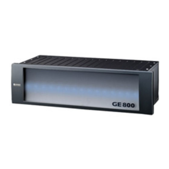
- Page 1 PRODUCT MANUAL ENGLISH GE 800 VERSION 1.1/1209...
- Page 2 GE 800 Manufacturer’s Reference: This equipment fulfils the requirements of the EU standard 89/336/EWG 89/336/EWG (EN 55022/55024). Therefore this equipment is CE-labelled. Please keep this description in safe custody! Application: With regard to the CE mark, the Intercom Server is suitable for the following types of application: residen- tial buildings, office and commercial premises, small businesses and industrial premises with public low- voltage mains supply.
-
Page 3: Table Of Contents
Connection of IP-Intercom Terminals Processor Card G8-GEP Connection of Intercom Terminals (Digital, Analogue) Networking Card G8-NET Connection Inputs/Outputs Connection of multiple Intercom Servers GE 800 LED-Status Indication Power Supply Card G8-GEN 5. CCT-Configuration Processor Card G8-GEP Configuration via IP or RS 232... - Page 4 GE 800 1.1/1209...
-
Page 5: Quick Start Guide
Quick Start Guide Quick Start Guide The Intercom Server GE 800 has been designed to meet the internal communication demands of large companies and organisations. Different functions of modern internal communication such as intercom, information and control can be integrated into a single system. By means of different subscriber cards with different feature levels and additional interfaces the central can be adapted to the individual needs with ease. -
Page 6: Extent Of Supply
1. Extent of Supply GE 800 1. Extent of Supply 1 Intercom Server GE 800 incl.: 19" Housing: 3 HE with snap-on lid G8-GEB Bus PCB (with 17 slots, of which 14 are empty) G8-GEN Power Supply Card (incl. installation board G8A-GEN) G8-GEP Processor Card G8-NET Networking Card (incl. -
Page 7: Additional Components
GE 800 2. Additional Components 2. Additional Components General Additionally to the Intercom Server for Start up of the system the following components are required: 1. Subscriber Cards Subscriber cards handle the speech communication as well as subscriber specific functions. For connection of IP-, Digital- and Analogue subscribers various cards in 4 feature level (B, C, D and P) are available. -
Page 8: Assembly Of Components
G8-S0 G8-SELCALL G8-TEL G8-V24 G8-V24-PRO G8-V24-PROIP Details see datasheet G8-TEL4 A second slot of the GE 800 is occupied by the G8-V24-PRO delivered with the G8-V24-PRO. A maximum of 100 outputs may be switched on at the same time. 1.1/1209... -
Page 9: Installation Of Plug-In Cards
The corresponding installation boards are mounted at the rear of the central. Installation boards Plug-in cards Tool for removing of installation boards Installation Boards for GE 800 The plug-in cards can be used with the following installation boards: ...available separately 0...included in Extent of Supply E...via ethernet port on G8A-NET G8A-C... -
Page 10: Cabling
2..TXD contacts 3..RXD 4..NC 5..GND 6..NC 7..NC 8..NC 9..NC Programming socket (parallel to G8-GEN) +30V Power supply GE 800 24V AC 24V AC e.g.: Grounding point for wrist strap Door opener Grounding grounding Power supply Installation Board G8A-NET UPLINK Ethernet (configuration) -
Page 11: Connection Of Ip-Intercom Terminals
Connection of Intercom Terminals (Digital, Analogue) For digital and analogue Intercom Terminals installation boards are required for connection to the Intercom Server (see ”Installation Boards for GE 800” on page Installation Board G8A-C for 4 Subscribers 1st subscriber 2nd subscriber... - Page 12 4. Cabling GE 800 Installation Board G8A-T for 8 Subscribers Slot n Slot n+1 1st subscriber subscriber whiteblue whiteyellow: A1 blue brown: whiteblue whiteyellow: C1 yellow black: subscriber 2nd subscriber Slot n whiteblue whitegreen: A2 green blue: whiteblue whitegreen: C2...
-
Page 13: Connection Inputs/Outputs
GE 800 4. Cabling Connection Inputs/Outputs Connection G8-8E8A Installation Board G8A-I Outputs Inputs whiteblue whitegreen:IN1 blue blue: whiteblue whitegreen:IN3 yellow yellow: whiteblue whitegreen:IN5 green green: whiteblue whitegreen:IN7 brown brown: whiteblue whitegreen: black black: whiteyellow : S6W whitebrown blue blue: whiteyellow: S7W... - Page 14 4. Cabling GE 800 Installation Board G8A-K S10W S11-16W S11-16W S11-16W S11-16W Connection G8-16E Installation Board G8A-I whiteblue whiteyellow: blue brown: whiteblue whiteyellow: yellow black: whiteblue whitegreen: green blue: whiteblue whitegreen: IN10 IN11 IN12 brown yellow: IN13 IN14 IN15 IN16...
-
Page 15: Connection Of Multiple Intercom Servers Ge 800
Multiple GE 800 Servers are connected via the Uplink and Downlink ports of the G8-NET card For the G8-NET card no special configuration is necessary A special “Discovery protocol” is used to localize the other GE 800 servers in the local network Attention: For this purpose the following IP address range is reserved! 231.255.x.233 to 231.255.x.239... -
Page 16: Network Redundancy
Note: For network redundancy the switch must support Rapid Spanning Tree RSTP functionality! Required Bandwidth in the Network The connection of GE 800 Intercom Servers creates a load on the IP network with the speech and con- nection data. These must be regarded when planning the system together with the network admini- strator. - Page 17 GE 800 4. Cabling Networking with existing systems The GE 800 Intercom Server is connected to the GE 700 via the two GEV-Ports on the G8A-NET instal- lation board of the G8-NET Card. Example 1: GE 800 GE 700 GE 700 Example 2:.
- Page 18 Limitations with synchronous connections Works like “Ring 2”: GE 800 always is “Clock Master” If CNET-W or CNET-E1 networking is used in the GE 700 system, the Servers GE 800 may only be connected on one side of the network! Otherwise non-synchronous connections must be used (LAN, WAN, S0).
-
Page 19: Cct-Configuration
5. CCT-Configuration 5. CCT-Configuration Configuration via IP or RS 232 Configuration of GE 800 Intercom Servers can be carried out via a RS 232 or standard network cable. For configuration of features see manual “PRO 800”. IP (Ethernet) Connect the PC for configuration with a network cable directly to the Intercom Server (ethernet port on the installation board G8A-NET) or with a switch in the network. -
Page 20: Start-Up Of A Networked System
5. CCT-Configuration GE 800 Start-up of a Networked System In networked systems each Server housing must be advised a unique number (Server-ID). There are two methods of advising each Intercom Server a Server-ID: For a maximum of 14 housings the Server-IDs can be set via the DIP-switches of the G8-GEP. This is the easiest method, because the PC does not need to be connected to each single housing. - Page 21 Router IP address: In this field the IP-address of the router (also "Gateway") is configured, via which the Intercom Servers communicate. A VLAN - ID is only required when the GE 800 is in a virtual network. The ID is entered as decimal value between 1 and 1023.
-
Page 22: Firewall Configuration
5. CCT-Configuration GE 800 The MAC - Address is displayed only in CCT, but cannot be changed. In the combo-boxes Uplink and Downlink the ethernet operation mode of the RJ45 ports can be selected: - Autonegotiation (Standard) - 10MBit / Half duplex... -
Page 23: Licensing
Activation process before it can be used. Detailed information can be found in the Intercom Server Installation Manual supplied with your system. You can direct any queries to your local Commend Partner whose contact details can be found at www.commend.com (click on Contact). L-COMWIN-N.C Rev.: AA... - Page 24 6. Licensing GE 800 Card Versions and Feature Levels The subscriber cards are available in the following versions and can be upgraded with the according licenses: G8-IP G8-GED G8-GET G8-IP-4B G8-GED-4B G8-GET-4B L8-IP-4C L8-GED-4C L8-GET-4C L8-IP-4D L8-GED-4D L8-GET-4D L8-IP-4P* L8-GED-4P*...
- Page 25 GE 800 6. Licensing Generation Licenses are valid for 15 generations. After that the licence becomes invalid. The following actions increase the generation number: One activation Moving of a licence to a different Intercom Server The licence is deactivated and re-activated internally When a licence is moved within an Intercom Server the generation number is not increased (see ”Card Area”...
-
Page 26: The Licensing Process
6. Licensing GE 800 The Licensing Process The following example shows a typical licensing process 1. Receiving of the serial number of the Intercom Server -> Allocation of the licence key to the serial number of the Intercom Server in CCT (see page 30). -
Page 27: Licensing In Cct
GE 800 6. Licensing Licensing in CCT Configuration CCT Receive the configuration of the Intercom Server. Menu Intercom Server > License administration Licence Pool Server Area Card Area Licence Pool In the licence pool (1) all available licenses are displayed, that have been added to the license pool... - Page 28 6. Licensing GE 800 Licence Pool Before a licence can be allocated to an Intercom Server it must be added to the licence pool. For this there are two possibilities: Enter purchased licenses (Run / Demo, see ”Enter purchased licenses”) Create temporary licenses (see ”Create temporary...
- Page 29 GE 800 6. Licensing The Card Area Address: In this field certain licenses are allocated to specific subscribers or interface ports (see ”Port-specific licenses” on page Licence Product: Displays the name of the licence product Licence Type (time left): Displays the licence type (see ”Licence Types”...
- Page 30 6. Licensing GE 800 Allocation of Licenses: 1. Add the acquired licenses to the licence pool (see page 2. Select the desired Server in the central area (2) 3. Drag-and-Drop the licenses onto the desired cards in the card area (3) (see page 4.
-
Page 31: Licence Website
Enter the serial number of the GE 800 / GE 300 Intercom Server in the field SN GEP/GEM In the field next to it the Licence key is entered, that is allocated to the cards in the Intercom Server... - Page 32 6. Licensing GE 800 Deactivation In the card area click on the licence with the right mouse button and select Enter/Change activati- on code Write down or copy the deactivation code http://license.intercom-online.cc/Deactivation.aspx?language=de Enter the code in the field Deactivation Code...
-
Page 33: Licence Activation At The Intercom Station
GE 800 6. Licensing Licence activation at the Intercom Station If no internet connection is available during CCT-configuration the activation codes can also be entered at an intercom station with Dot-Matrix Display (e.g. EE 811A). Entering Activation Codes Dial 9T8 at the station... -
Page 34: Configuration Of Ip-Terminals
7. Configuration of IP-Terminals GE 800 7. Configuration of IP-Terminals System Requirements Note: For the G8-IP as well as for the IP-Intercom Box ET 901, two different hardware generations are avai- lable. Thus, also the corresponding firmware generations are listed in this document: Firmware 03.x →... -
Page 35: Network Requirements
GE 800 7. Configuration of IP-Terminals Network Requirements IP-Addresses and Ports Each G8-IP must have a fixed IP-address For the ET 901/ET 908 the DHCP functionality is available If DHCP is not used, the ET 901/ET 908 must have a fixed IP-address... -
Page 36: Compatibility Ip-Terminals - Ipstationconfig
7. Configuration of IP-Terminals GE 800 Compatibility IP-Terminals – IPStationConfig Configuration of the IP-terminals with IPStationConfig is restricted to the respective firmware version in the IP-terminals: ET 901 2.0 build 3 Basic configuration only: IP-address / Subnet / Central-IP-address / Router-IP-address / Port Firmware download in ET 901 only possible with CCT Enhanced configuration &... -
Page 37: The Program Interface
GE 800 7. Configuration of IP-Terminals Packet.dll. Note: WinPcap does not work with all ethernet adapters. A list of compatible adapters can be found at http://www.winpcap.org/misc/faq.htm#Q-16. Particulary WLAN adapters may cause incom- patibilities. Installation IPStationConfig As code for the installation the standard CCT product key is used. -
Page 38: Firmware Download
7. Configuration of IP-Terminals GE 800 Presets In this window it is possible to define settings/ texts for multiple IP-subscribers automatically . Therefore it is also possible to advise e.g. consecutive IP-addresses automatically. By clicking on the arrow, the respective preset is advised to the selected subscribers in the table. -
Page 39: Configuration
GE 800 7. Configuration of IP-Terminals After selection of the file an acknowledgement dialog is displayed: Click on “Yes” to start the download: The current download status is indicated in the field Description. The result of the download is indicated in the field Status. - Page 40 7. Configuration of IP-Terminals GE 800 with NAT” on page 59). Attention: Single Port Protocol is only supported by IP-terminals with firmware versions as of: ET 901: 02.4 Build 03 / 03.1 Build 03 DSP900 (for ET 908): 03.1 Build 04 G8-IP: 02.5 Build 03 / 03.0 Build 02...
- Page 41 GE 800 7. Configuration of IP-Terminals *Note: The setting is saved in the ET 901 (min. firmware version 2.2) or in the ET 908 and is not saved in the Intercom Server configuration – it can be entered for information purposes only! In the column Host Name a name for the IP-subscribers can be entered which identifies the IP-sub- scriber for the DHCP server.
-
Page 42: Saving A Configuration
7. Configuration of IP-Terminals GE 800 Saving a configuration It is possible to save the configuration in a XML-file. In the menu File select Save XML-Settings or click on the button Save. A window for selection of the desired folder is displayed. - Page 43 GE 800 7. Configuration of IP-Terminals IP-subscribers with configured passwords When receiving the configuration of subscribers with configured passwords, red dots are indicated in the column Password. For these IP-stations / IP-boxes only the MAC-address is indicated. If the correct password is entered in the column Password, it is indicated with green dots. Addi- tionally the configuration of the device is displayed and can be changed and sent.
-
Page 44: Configuration Cct
7. Configuration of IP-Terminals GE 800 Configuration CCT G8-IP Select IP - Settings > tab Common: In the field Card IP Address a fixed, unique IP-address for each G8-IP has to be defined. In the field Subnet mask the subnet mask of the G8-IP is entered. - Page 45 GE 800 7. Configuration of IP-Terminals IP-Subscribers Select Subscriber > Station properties > IP-Terminals. In this dialogue the connections from the IP-subscriber card to the IP-subscribers are defined: Tab General In the field Card IP Address the IP-address of the appropriate IP-card defined at IP-Settings, is in-...
-
Page 46: General Information
General Information GE 800 General Information Expansion Basic expansion: Max. expansion per housing: Max. expansion (120 housings) Subscribers: 30,000 Outputs: 1000 Inputs: 1000 Line length Subscribers Station Series EE 311A, EE 811A Maximum cable length at diameter: (power supply from Intercom Server) -
Page 47: Standard Call Numbers
GE 800 General Information Maximum cable length at given diameter/cross section Reference 0.4mm 0.5mm 0.6mm 0.8mm 1.0mm 1.5mm 2.5mm Intercom station without display 650m 1,000m 1,500m 2,600m 4,200m Industrial station EE 6000 (A,B,C,D) 1,300m 2,000m 2,700m 4,900m 7,700m Power supply for EE 6000 (24V~),... -
Page 48: Dynamic Audio Channel Allocation
Conversations via G8-NET connection 32 conversations per G8-NET card to other Intercom Servers LAN-conversations via G8-NET reduce this number G8-NET to G7-GEV 28 conversations between GE 800 and GE 700. G8-CNET-E1 11 conversations (in each mode) G8-CNET-W Depending on configuration 4 to 12 conversations (in each mode) -
Page 49: Technical Data
GE 800 Technical Data Technical Data Intercom Server Basic Housing GE 800 Technical Data GE 800 AC power supply: 24 V +/– 5 % / 80 VA DC power supply: 24 V - 35 V / 80 W Emergency power consumption:... -
Page 50: Processor Card G8-Gep
325 g (0.72 lbs) Number of conversations between two GE 800: Maximum cable length between two GE 800 (IP): 100 m Maximum cable length between GE 800 and GE 700 (GEV): Cable type: Standard Cat. 5 Cables with RJ 45 plugs 1.1/1209... -
Page 51: Led-Status Indication
GE 800 LED-Status Indication LED-Status Indication Power Supply Card G8-GEN Power Supply Card for GE 800 with: Programming socket 2 relay outputs 2 inputs for floating contacts Audio input on/off switch Indication power supply Mains switch Intercom Server RS232 (for configuration) Fuse 3.15A... -
Page 52: Networking Card G8-Net
LED-Status Indication GE 800 LED-Status Indication Status Processor Card: LED blinks in rhythm of one second: Intercom Server is working correctly. LED blinks fast: during initializing. LED blinks slowly: during download of Server Software. LED is permanently off: no power, warm start or hardware fault. - Page 53 GE 800 LED-Status Indication Status NET: LED is permanently on: connection to network and to all defined Intercom Servers is ok (or no Inter- com Servers defined) LED is permanently off: no connection to network LED blinks: During logon and logoff of Intercom Servers Status GEV: LED is permanently off: Ring not in operation, no clock received.
-
Page 54: Subscriber Cards
DSP-Subscriber card for connection of up to 4 analogue subscribers via 4-wire lines. A maximum of 14 G8-GET cards can be used in a GE 800 IP-Intercom Server. Per subscriber one conversation is possible simultaneously (Non-Blocking). With the license L8-GET-DSP the DSP-features (see datasheet) are also available at analogue Intercom Terminals. -
Page 55: Input / Output Cards
GE 800 LED-Status Indication Input / Output Cards Input/Output Card G8-8E8A Plug-in card with 8 inputs for floating contacts and 8 relay outputs (4 of which are make contacts, 4 as make, open or switch over contacts) Status-LEDs: Ein-/Ausgangskarte 1. Ausgang 2. - Page 56 LED-Status Indication GE 800 LED-Status Indication Status Input/Output Card: LED blinks in rhythm of one second: the card is working correctly. LED is permanently off: no power or hardware fault. LED is permanently on: waiting for connection to the main processor (during initialising) or reset).
-
Page 57: Examples
GE 800 Examples Examples IP-Addresses The subnet mask specifies which portion of an IP-address represents the network ID (for identification of the subnet) and which portion represents the host ID (for identification of single network com- ponents). Subnet 1 Subnet 2... -
Page 58: Ip-Addresses With Subnetting
Examples GE 800 IP-Addresses with Subnetting The subnet mask specifies which portion of an IP-address represents the network ID (for identification of the subnet) and which portion represents the host ID (for identification of single network compon- ents). “Subnetting“ is e.g. using single bits from the host ID for forming further subnets. -
Page 59: Router Configuration With Nat
Addressing of the individual IP-stations/IP-boxes is carried out via the port numbers. IP - Settings > tab General Subscribers > Station properties > IP-Terminals > tab General Location 1 GE 800 No. 1 Slot 4 Connections: 172.16.0.10/16 ET 901 No.1: 16400 –... -
Page 60: Technical Support
Technical Support GE 800 Technical Support For more information about our products and services visit: www.software-manuals.com 1.1/1209...
Need help?
Do you have a question about the GE 800 and is the answer not in the manual?
Questions and answers