Table of Contents
Advertisement
Quick Links
Advertisement
Table of Contents
Troubleshooting

Related Manuals for Amico ARM


Summary of Contents for Amico ARM
- Page 1 Installation Instructions and Maintenance Manual Side to Side Monitor (SSM) Arm...
- Page 2 This Instruction Manual is your guide to ensure that you get the best performance out of the equipment. Amico Accessories is not responsible for any damage as a result of (but not limited to) abuse and other problems that may be a direct or indirect result of failure to comply with the instructions provided in this manual.
-
Page 3: Table Of Contents
Portrait and Landscape Adjustment Portrait and Landscape Limiter Cable Management: SSM Cable Management Cable Management: MRS Rail Cover Section 5: Troubleshooting, Maintenance and Product Classification 25-30 Cleaning Troubleshooting Preventive Maintenance (SSM Monitor Arm) 27-28 Part Number Matrix 29-30 Warranty Information... -
Page 4: Section 1: Installation Preparation
Mounting shelf (0-9, W) Extension arm (optional) NOTE: Amico does not provide any display hardware, nor the tools necessary for assembly (All above in grey text). NOTE: Tools and the monitor-dependant hardware set are not provided by Amico Accessories Inc. -
Page 5: Pre-Installation Information
WARNING: VERIFY THE WEIGHT OF THE DEVICE TO BE MOUNTED. SINGLE ARM SSM MONITOR ARMS ARE RATED FOR 30 LBS (13.6 KG), DUAL ARM SSM MONITOR ARMS ARE RATED FOR 15 LBS (6.8 KG). PLEASE REFER TO WEIGHT RATING LABEL, LOCATED EITHER ON THE TOP OR BOTTOM OF THE ARM ASSEMBLY, DEPENDING ON THE MODEL. -
Page 6: Typical Installation Reference For Ssm
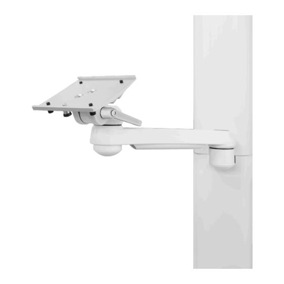
Typical Installation Reference for SSM SSM MONITOR ARM The diagram below illustrates the components referenced in relation to one another in the installation of the SSM Monitor Arm. Please follow the instructions outlined herein to ensure proper installation. 1. Monitor Mounting Adapter (Pg.12-18) -
Page 7: Section 2: Installation On Rail Systems
1. Support the bottom of the arm with one hand, guide the adapter into the top of the channel (Figure 1). 2. Once the arm is at the desired height, tighten the two set screws located at the bottom of the adapter using a 1/8" (3 mm) HEX key. -
Page 8: Mounting To Hill-Rom Vertical Rail (With The G-Track Adapter (Gta))
(Figure 3). 3. Position the SSM Arm at the desired height. Tighten the two regular nuts and then the two lock nuts on the top and bottom of the adapter using a 12 mm socket wrench. -
Page 9: Mounting To The Vrs (Vertical Rail System) With The V-Adapter
V-adapter screws to adjust into the profiles of the vertical rail. 1. Angle the SSM Arm from either side and guide the heads of the top and bottom screws into the channel of the rail (Figure 1-3) 2. -
Page 10: Mounting To The Ergotron And Rubbermaid Rail
Section 2: Installation on Rail Systems Mounting to the Ergotron and Rubbermaid Rail (15 lbs [6.8 kg] max. weight capacity) WARNING: TO PREVENT THE SSM ARM FROM FALLING DOWN THE CHANNEL, ENSURE THAT THE TWO NUTS ARE FASTENED AS TIGHT AS POSSIBLE. -
Page 11: Section 3: Monitor Installation
PLATE DOES NOT MATCH THE REQUIREMENT, PLEASE CONTACT AMICO ACCESSORIES INC. AT 1-877-264-2697 NOTE: Amico Accessories Inc. carries a variety of Mounting Shelves and adapters that attach to the SSM Arm. View the SSM Matrix on pages 29 and 30 for more information. -
Page 12: Monitor Shelf: 3" (76.2 Mm) Top/Back Mount, 5" (127 Mm) Top/ Back Mount And Vesa
3. Release the plunger and tighten the plastic screws by hand (Figure 4). Front of the shelf Plunger released Plastic Screws Plunger Lock Plunger pulled Mounting shelf 5" (127 mm) mounting shelf is shown above Figure 3 Figure 4 Amico Accessories Inc. -
Page 13: Monitor Shelf: 6" (152.4 Mm) Drop On
If the plunger does not lock automatically then lock the plunger manually by turning it. Tighten the locking screws by hand to the tightest possible position (Figure 2). Plunger Lock Mounting shelf Locking screws Mounting hole Mounting adapter plate Figure 1 Figure 2 www.amico.com 13... -
Page 14: Monitor Shelf: Philips Intellivue
NOTE: It is recommend to use M6 x 20 mm screws with thread locker or patched screws in order to eliminate possible dangers. 1. Attach the table top mount from Philips (not supplied by Amico) to the mounting shelf by securing the 3 screws through the shelf (Figure 2). -
Page 15: Monitor Shelf: Welch Allyn
(Figure 1). 2. Tighten the thumb screw to the tightest possible position (Figure 2). Thumb screw Thumb screw Front lip Figure 1 Figure 2 www.amico.com 15... -
Page 16: Monitor Mounting: Vesa 75/100
NOTE: Setting the VESA shelf horizontally can make the mounting procedure easier. NOTE: If the original monitor bolts are too large, determine the screw size and consult with Amico Accessories Inc. 1. Determine the monitor mounting configuration. VESA 75 (75 mm x 75 mm with M4 threads) or VESA 100 (100 mm x 100 mm with M4 threads). -
Page 17: Accessory Shelf: Disc
Section 3: Monitor Installation Accessory Shelf: Disc NOTE: It is possible to attach accessories to the top or bottom side of the SSM Arm using this same mount (Figure 1). NOTE: Amico Accessories Inc. carries a variety of different accessories that attach to the head of the SSM Arm. -
Page 18: Section 4: Adjustments
Dual Arm Rotation: To rotate at the end point (near wall), push on the side of the extension arm, near the mid-way point (Figure 2). To rotate at the midway point, hold the extension arm with one hand and push on the side of the SSM Arm with the mounted monitor in the direction desired (Figure 3). -
Page 19: Adjusting The Tension Bolt
1. The rotation tension bolt is located under the front-end of the arm. This is where the tension of the heads rotation is adjusted (Figure 1). 2. The mounted device rotates at the front of the arm. To rotate the device, push the corners of the device or the head (Figure 2 and 3). -
Page 20: Monitor Tilt
12 mm Socket Wrench Patient Monitor Allen Nut Shelf 1. To TIGHTEN the Tilt-Hinge (in order to set the desired tilt angle), TURN the Tilt-Setting Lever CLOCKWISE. [Turning the Lever COUNTER-CLOCKWISE will ENABLE tilt movement] Tighten Loosen Amico Accessories Inc. - Page 21 Step 3. Spring Figure 4 Figure 5 Figure 6 4. Turn the 12 mm hex-nut CLOCKWISE using the 12 mm socket wrench (Figure 7) to tighten. Figure 7 5. Test to confirm the tilt-angle is secure. www.amico.com 21...
-
Page 22: Rotation (Monitor Head)
(PAGE 28) FOR MORE INFORMATION. 1. The monitor rotates at the front of the arm. To rotate the monitor, push the corners of the device or the head while holding the SSM Arm. If the SSM is not held in place, the monitor head will rotate with the swivel post (Figure 1). -
Page 23: Portrait And Landscape Limiter
2. Re-mount the monitor (refer to page 16). Grab the monitor itself and turn to desired angle. The head will stop at the location of the stopper and prohibit further movement (Figure 2 and 3). Built in Stopper Rotational Tension Bolt VESA Rotation Stopper Figure 1 Figure 2 VESA Rotation Stopper Built in Stopper Figure 3 www.amico.com 23... -
Page 24: Cable Management: Ssm Cable Management
Cable Management: SSM Cable Management NOTE: A Cable guide is provided to facilitate routing of cables along the bottom of the arm. 1. Route cables between the openings and snap them into the cable guide. Larger cables may require the cable guide be pried apart. -
Page 25: Section 5: Troubleshooting, Maintenance And Product Classification
Damage caused by the use of unapproved substances or processes will not be warranted. It is recommended that you test any cleaning solution on a small area of the arm that is not visible to verify compatibility. -
Page 26: Troubleshooting
• Loosened/ damaged hardware • Shelf plunger pin does not engage • Plunger pin is locked Twist the plunger If the above solutions do not solve your symptoms or you are in need of parts/hardware, please contact Amico Accessories, 1-877-264-2697 Amico Accessories Inc. -
Page 27: Preventive Maintenance (Ssm Monitor Arm)
AND ACHIEVE MAXIMUM OPERATION LIFE. WARNING: THE INTERVALS SHOWN ON THE NEXT PAGE ARE RECOMMENDED. MAINTENANCE SCHEDULES SHOULD BE SHORTENED FOR SSM MONITOR ARM THAT SEE HEAVY USE. Please be sure to thoroughly check the areas illustrated below for SSM Monitor Arm: www.amico.com 27... - Page 28 Ensure the bracket is tightly attached to the adapter plate. MRS and Hill-Rom – Ensure the screws are fastened to the tightest possible position. VRS – Ensure the screw knobs are fastened to the tightest possible position. Amico Accessories Inc.
-
Page 29: Part Number Matrix
Section 5: Troubleshooting, Maintenance, Product Classification Part Number Matrix SSM-XXX-(Z) Single 9" (22.9 cm) SSM Arm 5" (12.7 cm) Shelf with 30° tilt limit Standard Channel Adapter Dual 9" (22.9 cm) SSM Arm 6" (15.2 cm) Drop on shelf Amico Vertical Rail Adapter Single 12"... - Page 30 Section 5: Troubleshooting, Maintenance, Product Classification Part Number Matrix SSM-LCD-XX-(Z) Single 9" (22.9 cm) SSM Arm Standard Channel Adapter Dual 9" (22.9 cm) SSM Arm Amico Vertical Rail Adapter Single 12" (30.5 cm) SSM Arm Hill-Rom Vertical Rail Adapter Dual 12" (30.5 cm) SSM Arm...
-
Page 31: Warranty Information
Amico Accessories Inc. will warrant its materials to be free from defect for an additional period of four (4) years, (five [5] years from the date of shipment). Within this period, Amico Accessories Inc. will replace any part which is proven to be defective, at no charge. - Page 32 Amico Accessories Inc. | 85 Fulton Way, Richmond Hill, ON L4B 2N4, Canada Toll Free Tel: 1.877.264.2697 | Tel: 905.763.7778 | Fax: 905.763.8587 Email: info@amico-accessories.com | www.amico.com AMICO-AA-SSM-SIDE-TO-SIDE-PATIENT-MONITOR-ARM-MANUAL 05.13.2021...
Need help?
Do you have a question about the ARM and is the answer not in the manual?
Questions and answers