
Subscribe to Our Youtube Channel
Related Manuals for Pego 100N MASTER3


Summary of Contents for Pego 100N MASTER3
- Page 1 VISION TOUCH AB User and maintenance manual ENGLISH READ AND KEEP Rel. Software: VT_AB_9_0_0_2 REV. 01-19 ELECTRICAL BOARDS FOR REFRIGERATING INSTALLATIONS...
- Page 2 VISION TOUCH AB Thank you for choosing VISION TOUCH AB by PEGO s.r.l. Reading this manual thoroughly will guide you through proper installation and better use of the various features. We therefore recommend keeping this manual near the controller to make use of it during the device installation, configuration and use.
- Page 3 Standard equipment for assembly and use Pag. 10 Installation and assembly ELECTRICAL CONNECTIONS CHAP. 3 Pag. 12 Console / 100N Master3 power supply and connection Pag. 14 Connection of digital outputs on 100N Master3 Pag. 15 Connection of digital inputs on 100N Master3 Pag. 16 Connection of analogue inputs on 100N Master3 Pag.
-
Page 4: Table Of Contents
VISION TOUCH AB PARAMETERS CHAP. 8 Access to the “Parameters” menu” Pag. 47 Pag. 48 Description of parameters setting page Pag. 49 Parameters menu items list Pag. 51 8.3.1 Process adjustment Pag. 51 8.3.2 Defrost cycles Pag. 52 8.3.3 Ventilation Pag. -
Page 5: Pag.
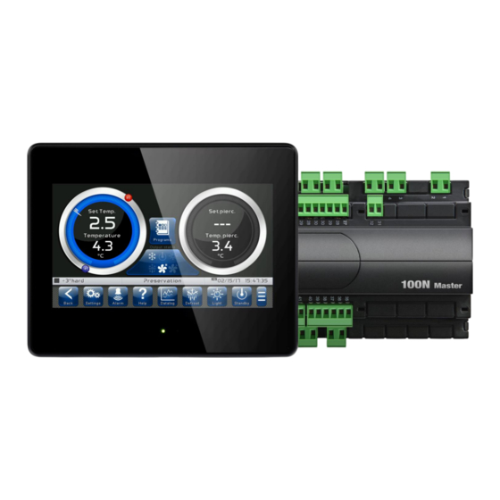
It allows the quick refrigeration of the product, with end due to time or piercing probe temperature. The system consists of the 100N MASTER3 unit, on which all the electrical connections are made, and the VISION TOUCH AB control console, equipped with 7'' TFT display with capacitive touch screen combined with a highly advanced software and a highly user friendly interface that allows easy use. -
Page 6: Pag.
VISION TOUCH AB Temperature range -45°C/+45°C. 20 completely customizable programs that can be stored on the instrument, 8 of which are already preloaded: • cycle by time +3° hard; • cycle by time +3° soft; • cycle by temperature +3° hard; •... -
Page 7: Pag.
VISION TOUCH AB 100N MASTER3 IDENTIFICATION DATA The device described in this manual has, on the side of 100N MASTER3 and on the back of the VISION TOUCH AB console, a plate bearing its identification data: • Name of Manufacturer •... -
Page 8: Pag.
VISION TOUCH AB TECHNICAL FEATURES Power supply 110 - 230 V~ 10% 50Hz / 60Hz Voltage Max power consumption (electronic controller only) ~ 15 VA Climatic conditions Operating temperature -5 ÷ +50°C Storage temperature -10 ÷ +70°C Relative ambient humidity Less than 90% RH General features Type of connectable probes (temperature) -
Page 9: Installation
• 2 temperature probes; • 1 plug telephone cable (5m); • 1 Quick guide to electrical connections; • 1 Vision Touch AB (200VTOUCHAB); • 4 media for Vision Touch console; • 100N MASTER3 (200100NMSTH3); USER AND MAINTENANCE MANUAL Pag. 9 Rev. 01-19... - Page 10 VISION TOUCH AB INSTALLATION AND ASSEMBLY Fig. 1: Install the 100N MASTER3 module on the DIN guide and close the bottom clamps to hold it in place. 177mm Fig. 2: VISION TOUCH AB console drilling template. Fig. 3: Configure properly the side switch (if present) to reverse the viewing angle of the display.
- Page 11 VISION TOUCH AB Fig. 4: Fasten the VISION TOUCH AB console by means of the four media to be inserted in their specific seats. Tighten each screw until the entire border front of the console rests on the panel. USER AND MAINTENANCE MANUAL Pag.
- Page 12 POWER SUPPLY AND CONNECTION CONSOLE/100N Master3 1) Connection between the console and 100N Master3 with distance within 10m: Connect the ground to the GND terminal of M2 in the console (functional ground).
- Page 13 VISION TOUCH AB 2) Connection between the console and 100N Master3 with distance within 500m: Connect the ground to the GND terminal of M2 in the console (functional ground). This connection helps to limit the effects of the electromagnetic noise on the control system.
- Page 14 VISION TOUCH AB DIGITAL OUTPUT CONNECTION ON 100N MASTER3 POSSIBLE CONFIGURATIONS ÷ DIGITAL OUTPUTS DO1 DO12 Access menu: Parameters > Configure I/O > Digital outputs 0 = Disabled 1 = Cold 2 = Fan high speed 3 = Fan low speed...
- Page 15 VISION TOUCH AB DIGITAL INPUT CONNECTION ON 100N MASTER3 POSSIBLE CONFIGURATIONS ÷ DIGITAL INPUTS DI1 DI12 Access menu: Parameters > Configure I/O > Digital inputs 0 = Disabled 1 = Micro gate 2 = Alarm 3 = Stand-by 4 = Compressor protection...
- Page 16 VISION TOUCH AB ANALOGUE INPUT CONNECTION ON 100N MASTER3 POSSIBLE CONFIGURATIONS ÷ ANALOGUE INPUTS AI1 Access menu: Parameters >Configure I/O >Analogue inputs 0 = Disabled 1 = Ambient temperature (NTC) 2 = Evaporator temperature (NTC) 3 = Piercing probe (NTC)
- Page 17 VISION TOUCH AB ANALOGUE OUTPUT CONNECTION ON 100N MASTER3 POSSIBLE CONFIGURATIONS ÷ ANALOGUE OUTPUTS AO1 Access menu: Parameters >Configure I/O >analogue outputs 0 = Disabled 1 = Speed of the evaporator fans DESCRIPT. TYPE OF ANALOGUE DEFAULT SETTINGS TERMINALS TERMINALS...
- Page 18 VISION TOUCH AB CONNECTION TO RS-485 FOR TELENET OR MODBUS-RTU Connect the earth to the GND terminal of M3 in the console (functional earth). This connection helps to limit the effects of the electromagnetic noise control system. ground connection must be made in a manner consistent with applicable regulations.
- Page 19 VISION TOUCH AB CHAPTER 4: SWITCHING ON COMMISSIONING When the controller is switched on for the first time, the "Language Selection" and "time and date setting" pages of the system are displayed to facilitate the user in starting up the controller.
- Page 20 VISION TOUCH AB SWITCH-ON CONTROL Every time the controller is switched on, an information pop-up is displayed with the starting date and time, requesting the user to acquire the information by pressing "OK". This allows to verify the return from an electrical blackout. Controller starting date and time...
- Page 21 VISION TOUCH AB CHAPTER 5: USER INTERFACE This section illustrates the features and instructions for using the display, the light indicators and the buttons making up the user interface of the VISION TOUCH AB, and therefore represent an essential requirement to correctly program and configure the controller.
- Page 22 VISION TOUCH AB MAIN DISPLAY The section of the main display views the work and setting pages based on the position (for example Home, Configuration, phase). A detailed description of the various pages will be made further on in this manual. STATUS BAR The Status Bar is in the lower part of the display (above the Button Bar, if applicable) and displays some important information relating to the status of the device, such as the name...
- Page 23 VISION TOUCH AB BUTTON BAR The Button Bar is at the bottom of the display and views the main operating buttons and their status. It is always present except when, in some rare cases, it is temporarily hidden to fully exploit the display. The buttons can have different shapes but always include an icon, a description and a colour that identifies the status.
- Page 24 VISION TOUCH AB Description of buttons in Button Bar: BACK: Inside a menu or level: Go back to previous level or menu. In a HOME page: Go back to the previous Home page. Indietro If held for longer than 3 seconds: Go back to HOME1 page PARAMETERS: Enter the parameter setting menu Parametri ALARMS: Enter the alarm log menu...
- Page 25 VISION TOUCH AB MANUAL CELL LIGHT BUTTON: Manually activates/deactivates the cell light. Green: Light active Blue: Light not active Flashing light icon: Indicates the forced activation of the light from the digital input of the Luce micro gate open. With the open gate digital input, the manual cell light, defrost, pause and air cycle buttons are deactivated.
- Page 26 VISION TOUCH AB GESTURE The Vision Touch, aside from normal pressing of keys, on some pages supports gestures which allow the user a more natural and therefore simpler interaction. Change Home Page: On one Home page, move your finger to the left or to the right to pass from one Home page to the next one or to the previous one.
- Page 27 VISION TOUCH AB Change parameters with roll selection: Move your finger up or down by one roll to change its value. (Suggestion: move your finger starting from the outside of the roll and pass through it completely). If the value you are trying to set is not allowed and is not included in the range of the variables, the background of the roll will turn red for an instant indicating that the action is not allowed..
- Page 28 VISION TOUCH AB "Edit" mode in Home 1 and 2 pages: When you are on one of the Home pages, touch the screen at a point which is not a button for more than three straight seconds to enter edit mode of the page itself. To exit this mode, press the "Back" button or wait for the automatic exit after one minute of inactivity.
- Page 29 VISION TOUCH AB CHAPTER 6: HOME PAGES The "Home" pages are the main interface of the controller from whence it is possible to access the mostly used features. They are divided as follows: PRESERVATION PROGRAMS Display/modify the ambient temperature setpoint, Complete management of programs (Recipes): display piercing probe temperature value, display Display, create, edit, delete and load.
- Page 30 VISION TOUCH AB PRESERVATION –Temperature, I/O state Management The "PRESERVATION" page allows selection, display and modification of the room temperature control and access to the recipes page using the 'Select program' button. When in visualization, it is divided into 4 main sections: •...
- Page 31 VISION TOUCH AB Temperature adjustment dial: Displays all that regards temperature adjustment, in particular: • The temperature set point (can be modified by pressing the dial for 3 sec) • Adjustment probe temperature measurement • The status of the call (Cold /No call) •...
- Page 32 VISION TOUCH AB Multifunction data visualization dial: it consists of two parts which, when touched, cyclically alternate the data displayed. The following are the various screens and their related meanings. Note: Some data is only viewed if the relative function is enabled in the configuration parameters.
- Page 33 VISION TOUCH AB PRESERVATION – Modify the Temperature setpoint “Modify setpoint” mode on the PRESERVATION page: Touch one of the adjustment dials on the screen for more than three consecutive seconds. Once you have entered the edit mode, it is possible to change the temperature set point currently in use by rotating the wheel clockwise to increase or anti-clockwise to decrease the value of the set point to be modified.
- Page 34 VISION TOUCH AB Evaporator fan speed selection buttons: Evaporator fans high speed. Evaporator fans low speed. Evaporator fans with 0-10V output. This button is only displayed if the EFa parameter = 1. 100 % 100 % Press + or - to increase or decrease the evaporator fan speed.
- Page 35 VISION TOUCH AB AUTOMATIC PROGRAMS – Display, create, start and edit Button to access the automatic programs display page: Program selection: Press this button to enter the automatic program management and display page. Programmi • The "Program list" allows complete management of the programs (Recipes): view the list, create, edit, delete and start the program.
- Page 36 VISION TOUCH AB Editing programs: Press the 'Edit' button to access the program editing page. Edit / start bar Bar to create of an existing program a new program Navigation buttons to move from one page to another of the program list By pressing the "Back"...
- Page 37 VISION TOUCH AB Program identification Program name Program Edit button icon Start program AUTOMATIC PROGRAMS - description of the Program Phases There can be up to 4 phases in a program, split as follows: Quick-refrigeration: In this phase the temperature is brought to a very low value to quickly cool the freshly cooked food.
- Page 38 VISION TOUCH AB AUTOMATIC PROGRAMS – Preloaded programs +3°C SOFT TEMPERATURE Phase 1 Phase 2 Preservation 0.0 °C +2.0 °C Ambient set 3.0 °C Piercing set Duration 90 min +3°C HARD TEMPERATURE Phase 1 Phase 2 Preservation -20.0 °C 0.0 °C +2.0 °C Ambient set 10.0 °C...
- Page 39 VISION TOUCH AB AUTOMATIC PROGRAMS – Add / Edit Program Phases The button appears when the program is stopped and the PROGRAM LIST is accessed. Edit program: Enters the program edit page. Edit Generic settings of the program. Enabling the single phases. Change the settings of the enabled phases.
- Page 40 VISION TOUCH AB By pressing the button on the left of the program icon at the top of the summary bar, you enter the following program options configuration page. Program generic settings. General option configuration page of program: Select icon: Notice (popup) at program end: This button accesses the database of The user is informed of the end of a program...
- Page 41 VISION TOUCH AB By pressing the button at the bottom left corner of each phase you enter the phase configuration page. Phase configuration page 1/2: Confirm and cancel Selected phase name modifications buttons Phase Ambient Product Buttons for moving between configuration pages.
- Page 42 VISION TOUCH AB Phase configuration page 2/2: Fans: Management of fan switching modes. Evaporator fan speed selection in selected phase. If the 0-10V output is selected for fan speed regulation (parameter EFa=1 in the Ventilation menu present in the parameters) there is a speed selection roll instead of these two flags (20-100%).
- Page 43 VISION TOUCH AB AUTOMATIC PROGRAMS – Automatic cycle The "automatic cycle" is displayed automatically after a program is started. At the end of the program or when the STOP button is pressed, the "Preservation" screen is automatically displayed. The page is split into 2 main sections: •...
- Page 44 VISION TOUCH AB "Edit setpoints" mode on the CURRENT PROGRAM (SETPOINT) page: Touch one of the adjustment dials on the screen (ambient or product temperature) for more than three consecutive seconds. ''CHANGED'' appears in the dials if the current values of the setpoints are different from those set in the program. Press the "Graph"...
- Page 45 VISION TOUCH AB At this point a graph with the trends of the ambient temperature setpoint (red line) and product temperature setpoint (blue line) set in each phase of the program will be displayed. The complete configuration of a phase can be viewed (but not edited) by pressing the button.
- Page 46 VISION TOUCH AB CHAPTER 7: ACCESS LEVELS Access levels to parameters (User/ installer) The controller has two access levels to the parameters and to the functions: “User” and “Installer”. The default setting is User that has a parameter menu that can be customised by the installer.
-
Page 47: Parameters
VISION TOUCH AB CHAPTER 8: PARAMETERS Access to Parameters menu Press the "Parameters" button in the Button Bar to access the control parameters setting menu PARAMETERS: Enters the parameter setting menu Parametri Process regulation Probes calibration Defrost Datalogger Communication RS485 Fans Piercing probe Web server... -
Page 48: Description Of Parameters Setting Page
VISION TOUCH AB Description of parameter setting page Press the "Settings" button in the Button Bar to access the controller parameters setting menu. Each sub-menu contains the name of the variables that can be set, a brief description in the selected language and the currently set value. Variable name Variable description Current value... -
Page 49: Machine Protection
VISION TOUCH AB List of parameter menu items Listed below is the complete list of items displayed in the “Parameters” menu. General description Name Symbol Chapter Process General process parameters 8.3.1 regulation Defrosting, dripping, evaporator presence Defrosts 8.3.2 settings Fans activation and relative speed settings, 0- Fans 8.3.3 10 V outlet setting... -
Page 50: Info
VISION TOUCH AB VISION TOUCH AB device information Info 8.3.16 (software version, memory occupied) Management of protection level: Password 8.3.17 user/installer access, menu configuration Digital/analogue inputs/outputs test, touchscreen interface operation test Test center 8.3.18 Configuration of functions associated to digital/analogue inputs/outputs 8.3.19 Configure I/O Verify the status of the digital and analogue... - Page 51 VISION TOUCH AB Process regulation 8.3.1 “Process adjustment” allows setting the differentials of the AB. The “Process adjustment” menu can be accessed from the main Configuration page (“Parameters” Button). The display of this item can be set in the “Password” sub-menu => “Configure user level menu”...
- Page 52 VISION TOUCH AB VARIABLES MEANING VALUES DEFAULT Defrost interval (hours). 0 ÷ 24 hours Maximum defrost period (minutes) 1 ÷ 240 min 25 min Defrost end Set-point. Defrosting is not carried out if the temperature detected by the defrost probe is higher than the -35 ÷...
- Page 53 VISION TOUCH AB MEANING VALUES DEFAULT VARIABLES Fan pause after defrost (minutes) Allows to keep the fans stopped for a time F5 after dripping. 0 ÷ 10 min 0 min This time starts counting from the end of dripping. If dripping is not set, at the end of defrost the fans pause immediately.
- Page 54 VISION TOUCH AB VARIABLES MEANING VALUES DEFAULT 0 = disabled Enabling the piercing probe 1 = enabled Delay time for out-of-range piercing probe alarm (Efo) when a program that uses the piercing probe is in progress. 0 ÷ 240 min 5 min Temperature differential to evaluate (when starting a program) if the piercing probe is not inserted correctly.
- Page 55 VISION TOUCH AB Alarm regulation 8.3.6 “Alarms adjustment” allows to set the minimum and maximum temperature and the delay between the alarms signal and display (disabled if automatic program running). The “Alarms adjustment” menu can be accessed from the main Configuration page (“Parameters”...
- Page 56 VISION TOUCH AB VARIABLES MEANING VALUES DEFAULT Time interval between one registration and the next one (0 = datalogger disabled). 0 ÷ 60 min 0 min To ensure one year data recording set int > 10 min.. Asynchronous registration. In case of activation/deactivation of a temperature alarm a data recording is forced.
- Page 57 VISION TOUCH AB Web server 8.3.10 The "Web server" menu allows setting the Web server configuration. This menu is accessible from the Main Configuration page (“Parameters” Button). The visibility of this item can be set in the submenu "Password" => “Configure user level menu” and by selecting the “Web server”...
- Page 58 VISION TOUCH AB Settings page Changes are applied when the “Confirm” button is pressed Enable / disable DHCP Configure Port Configure IP address Configure Netmask Configure Gateway - DHCP: enable / disable configuration request to the DHCP server. If enabled, the IP address associated with Vision Touch is assigned by the DHCP server (if it is present on the local network).
- Page 59 VISION TOUCH AB The page “User name” allows configuring the Username to be used during login on the Vision touch Web page (the password coincides with the Vision Touch Installer password). Username Web Password Browser Web (default: adminlogin) (default: 100) USER AND MAINTENANCE MANUAL Pag.
- Page 60 VISION TOUCH AB Command enable page The Wce parameter allows enabling or disabling commands and edits parameters from the Web page, regardless of the type of user (user or admin) that accesses the Web page. Info page The "Info Page" allows checking the current Web configuration of the Vision Touch AB. DHCP: DHCP assignment status Host: name used in the web browser address bar (linked to the serial number) IP / Netmask / Gateway: current configuration (set either locally or by DHCP)
- Page 61 VISION TOUCH AB Mail 8.3.11 The “Mail” menu allows setting the alarm mail configuration. The menu can be accessed from the main Configuration page (“Parameters” Button). The display of this item can be set in the “Password” sub-menu => “Configure user level menu” and by selecting the “Mail” item (installer login required).
- Page 62 VISION TOUCH AB Language 8.3.12 The “Language” menu allows to change the control unit language. The menu can be accessed from the main Configuration page (“Parameters” Button). The display of this item can be set in the “Password” sub-menu => “Configure user level menu” and by selecting the “Language”...
- Page 63 VISION TOUCH AB If automatic synchronization via the Web is active, the control connects to an external service that automatically determines the correct time zone and sets the date and time considering any summer / winter time. The status of the last synchronization attempt (referred to as "Last update") can be: - None: no attempt to synchronize (for example at first power up);...
- Page 64 It is advised to export the data history before proceeding with the update. Software updating procedure: Copy the update file "VT_AB_#_#_#_#.pego" (the symbols # represent the progress of the version) to an empty USB pen drive. Only the update file must be present in the pen drive.
- Page 65 VISION TOUCH AB The update finishes as soon as the controller goes back to the "Preservation" screen; at this point you can remove the USB key and resume normal use. The new Software version can be checked in the "Parameters" > "Info" menu under "Application Version".
- Page 66 VISION TOUCH AB User Password Page Display locked with password Maintenance login Password entry to access the User screen lock password setting installer level (Default password: 0100) Installer Password Page Exit from installer mode Selection of configuration menu elements visible by the user Display locked with password Maintenance login Configure user level menu...
- Page 67 Master3 connected to the VISION TOUCH AB. One can also verify the operation of the touchscreen sensors. The “Test centre” function is reserved to expert users. Pego S.r.l. disclaims any liability for damage to the system due to improper use of this function.
- Page 68 The “Digital outputs test” allows to manually force the digital outputs of the connected 100N Master3. Access to this menu put the control unit in “Stand by”: the time progress of an ongoing program is not altered but all output functions are disabled.
- Page 69 The “Analogue outputs test” allows to manually force the analogue outputs of the connected 100N Master3, by setting the values manually between 0 and 10V. Access to this menu put the control unit in “Stand by”: the time progress of an ongoing program is not altered but all output functions are disabled.
- Page 70 “Configure I/O” allows to set the function associated to each input/output of the connected 100N Master3. The “Configure I/O” function is reserved to expert users. Pego S.r.l. disclaims any liability for damage to the system due to improper use of this function.
- Page 71 “Digital outputs” allows to change the function associated to each digital output of the connected 100N Master3. The modification of an output puts the control unit in “Stand by”. In the event a function is not associated to at least one output, the eventual call from the control unit will not activate any digital output (only the status icon will be activated to indicate a call).
- Page 72 “Analogue outputs” allows to change the function associated to each analogue output of the connected 100N Master3. The modification of an output puts the control unit in “Stand by”. In the event a function is not associated to at least one output, the eventual call from the control unit will not activate any analogue output (only the status icon will be activated to indicate a call).
- Page 73 VISION TOUCH AB I/O status 8.3.20 “I/O Status” allows the status of each input/output of the connected 100N MASTER3 to be displayed. The “I/O Status” menu can be accessed from the main Configuration page (“Parameters” Button). The display of this item can be set in the “Password” sub-menu => “Configure user level menu”...
-
Page 74: Diagnostics
VISION TOUCH AB CHAPTER 9: DIAGNOSTICS Diagnostics VISION TOUCH AB If any faults occur, the controller informs the operator, by means of alarm codes visualised on the display (via pop-up or on the ‘Alarms’ page) and an acoustic signal emitted by a buzzer inside the operating Console (if enabled). - Page 75 VISION TOUCH AB Check the connection between the two units. Switch the Vision Touch off and MASTER board initialisation error. on again. If the problem persists, contact the technical assistance service. Maximum temperature alarm. Check the compressor status. The environment has reached a temperature ...
- Page 76 VISION TOUCH AB Delete the memory of the Data logger by setting the parameter Mem = 1. Turn off and on again the Vision Read / Write Error on Data logger Memory. Touch. When the alarm is called off, reset (The alarm stops the Data logger recording and sets the parameter int = 0) the Data logger records by...
-
Page 77: Alarms Management
VISION TOUCH AB Alarms management By pressing the “Alarms” button one accesses the relative management page that contains the log relating to the last 30 alarms detected. The alarms can take on different colors: - RED ALARM: indicates an alarm in progress, not solved. - ORANGE ALARM: when a red alarm is cleared because the cause is solved, it turns orange and becomes an alarm to be acquired. -
Page 78: Pop-Up Management
VISION TOUCH AB Pop-up management Pop-ups are elements that appear on the screen in order to call the user's attention to particular situations that may occur during the normal use of the VISION TOUCH AB control unit. RED POP-UP YELLOW POP-UP It may indicate: - activated alarm warning The operation one is about to perform is critical. -
Page 79: Datalogger
VISION TOUCH AB CHAPTER 10: DATALOGGER DATALOGGER 10.1 Datalogger function activates by setting the value of parameter "int" (“Datalogger” menu) greater than 0; if registrations are active, the symbol appears on the status bar. DATA EXPORT IN CSV FORMAT: (Included in Extended Button bar) Exports registered data in a CSV file on USB or SD support. - Page 80 VISION TOUCH AB REGISTRATIONS HISTORY: (Included in Extended Button bar) Once pressed, the day selection screen opens for which the registered data Datalog are shown. Chart options. Show ambient temperature; Show product temperature; Auto scale; Data table; Upon confirming the date, the registration graph appears: Temperature values range Date and time of first registration Date and time of last registration...
- Page 81 VISION TOUCH AB If ‘Data table’ option is selected, the registration list appears: Power on Standby Active cycle Move your finger up or down to pass to the next or previous data page. USER AND MAINTENANCE MANUAL Pag. 81 Rev. 01-19...
-
Page 82: Installation
VISION TOUCH AB CHAPTER 11: WEB SERVER INSTALLATION 11.1 The Web configuration of the Vision Touch AB depends on the type of connection. - Direct connection to the PC The network card of the computer must be configured in order to have the assignment of the DHCP address activated. - Page 83 VISION TOUCH AB LAN Connection If connected to a LAN where a DHCP server is present (and the DHCP solicitude is enabled on the Vision Touch, look at chap. 8.3.10), the Vision Touch will acquire a free IP address. In this case it is possible to consult the IP address acquired through the “Info Page”...
-
Page 84: Web Interface: User Access
VISION TOUCH AB WEB INTERFACE: USER ACCESS 11.2 The access to the Web page of the Vision Touch is subject to the access control through Username and Password. It is possible to access to the Web pages of the Vision Touch in other two modes: - basic user: inserting in the “Username”... -
Page 85: Web Interface: Pages
VISION TOUCH AB WEB INTERFACE: PAGES 11.3 The web interface counts with some fixed sections: On the left: browsing menu of the pages. At the top: name of the page, serial number and kind of connected user. On the right: content of the page. - Homepage Piercing probe Browsing menu... - Page 86 VISION TOUCH AB - I/O (Inputs / Outputs) Input / Output Clamp Input / Output Input / Output status PIN on the 100N description (digital or If digital: analogical) MASTER - green: active input / output - grey: inactive input / output If analogical: You visualize the analogical input / output value...
- Page 87 VISION TOUCH AB - Alarms In the “Alarms” page are visualized all the red falg alarms and those which have intervened, such as they are memorized in the Alarms page of the Vision Touch (look at chap. 10.2, Alarm Gesture). The background color is indicative for the type of alarm: - Red background: red flag alarm (the starting instant is indicated).
- Page 88 VISION TOUCH AB - History => Table In the “History => Table” page you can visualize and print memorized daily data, recollected in the memory of the Vision Touch. In order to view the records, select a date from the calendar (click on the “Select a date” field) and press the “Load” button. Alarm of high Alarm of low Stand-by active...
- Page 89 VISION TOUCH AB - History => Graph In the “History => Graph” page you can visualize and print the graph of daily data recollected in the memory of the Vision Touch. In order to view the graph, select a date from the calendar (click on the “Select a date”...
- Page 90 VISION TOUCH AB - Controls => Program In the "Program" page, it is possible to select, start and stop the execution of the programs saved in the memory of the Vision Touch. The "Play" and "Stop" buttons can be disabled with Wce parameter.
- Page 91 VISION TOUCH AB When a program is running, the following page is showed: Info about product ready time Program name Stop the program and current time Steps performed or in progress Current temperature Next steps (full color) (black triangle) (Transparent) Note: it is possible to deactivate the phase display by clicking on the phases name in the legend.
- Page 92 VISION TOUCH AB - Controls => Parameters Parameters menu hidden to the basic user (configuration in Parameters menu the Password menu on the Vision Touch) Click on the indicator in order to Note: the admin user always has access to the complete list of visualize the list of the the menu.
-
Page 93: Uv Light
VISION TOUCH AB - Info CHAPTER 12: OPERATIONS UV light 12.1 Switching on the UV light allows sterilization of the inside of the quick-refrigeration room. It can be activated using the special key only when the instrument is in standby; the UV light is switched off automatically when the standby is removed, a cycle is activated, the door is opened or the time set in the 'tuv' parameter expires. - Page 94 DEL FABBRICANTE: THIS DECLARATION OF CONFORMITY IS ISSUED UNDER THE EXCLUSIVE RESPONSIBILITY OF THE MANUFACTURER: PEGO S.r.l. Via Piacentina 6/b, 45030 Occhiobello (RO) – Italy – DENOMINAZIONE DEL PRODOTTO IN OGGETTO / DENOMINATION OF THE PRODUCT IN OBJECT MOD.: VISION TOUCH AB (cod.
-
Page 95: Warranty Terms
The intervention service in warranty can be refused when the equipment is modified or transformed. Under no circumstances Pego S.r.l. will be liable for any loss of data and information, costs of goods or substitute services, damage to property, people or animals, loss of sales... - Page 96 Tel. +39 0425 762906 Fax +39 0425 762905 e.mail: info@pego.it – www.pego.it AFTER-SALES ASSISTANCE CENTRE Tel. +39 0425 762906 e.mail: tecnico@pego.it Distributor: USER AND MAINTENANCE MANUAL Pag. 96 Rev. 01-19 PEGO s.r.l. reserves the right to make amendments to this user manual at any moment.
Need help?
Do you have a question about the 100N MASTER3 and is the answer not in the manual?
Questions and answers