
Related Manuals for I-PEX ISH VW


Summary of Contents for I-PEX ISH VW
- Page 1 ® Instruction Manual RS0789 January 6, 2021 H. Naoi S. Tono E. Kawabe RS0615 August 7, 2019 H. Naoi J. Tateishi E. Kawabe Rev. Date Prepared by Checked by Approved by Confidential C I-PEX Inc. QKE-DFFDE09-03 REV.8 1 / 29...
-
Page 2: Table Of Contents
Document No. ISHVW CONNECTOR Instruction Manual HDM-0012 Contents 1. Purpose ・・・・・ Sheet 3 ・ ・・・・・ Sheet 3 2. Applicable items ・ 3. Crimping procedure ・・・・・ Sheet 4 ・ ・・・・・ Sheet 14 4. Terminal insertion ・ 5. Secondary lock installation ・・・・・ Sheet 15 ・... -
Page 3: Purpose
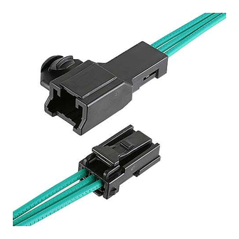
Document No. ISHVW CONNECTOR Instruction Manual HDM-0012 1.Purpose The Manual explains the handling of ISHVW CONNECTOR. 2.Applicable items The Manual is applicable to the items listed below. Name Part No. Image FEMALE TERMINAL VT001-512 MALE TERMINAL VT002-012 MALE CONNECTOR FEMALE CONNECTOR Fig.1 Product summary Confidential C 3 / 29... -
Page 4: Crimping Procedure
Document No. ISHVW CONNECTOR Instruction Manual HDM-0012 3. Crimping procedure 3-1.Applicable wires Terminal Type Terminal Parts No. Applicable Wire FEMALE TERMINAL VT001-512 Wire size:0.3mm ,0.5mm Insulation outer diameter:φ1.60mm MAX. MALE TERMINAL VT002-012 3-2. Wire strip length ①Strip the insulation off by 3.0±0.1mm (see Fig.2) ②Check to see that there is no damage to the conductors or insulation, cut off conductors, short conductors and deformed conductors as shown in Fig. - Page 5 Document No. ISHVW CONNECTOR Instruction Manual HDM-0012 3-3. Terminal part names 3-3-1. Female terminal Fig.4 Female terminal part names Fig.5 Male terminal part names 3-4.Crimping requirements Crimp dimension Crimped terminals must satisfy the crimp dimension specified in Table 1. Table 1 Crimp dimension Insulation Wire barrel Wire barrel...
- Page 6 Document No. ISHVW CONNECTOR Instruction Manual HDM-0012 Measuring method for crimp dimension is described below. Use the micrometer shown in Fig.6 for measurement of each part. Fig 6. Micrometer (1)-1. Measuring method for wire barrel crimp height is described below. To measure the wire barrel crimp height, pinch the top of the wire barrel (winding side) and the bottom of the wire barrel with a micrometer.
- Page 7 Document No. ISHVW CONNECTOR Instruction Manual HDM-0012 (1)-2. Measuring method for insulation barrel crimp height is described below. To measure the insulation barrel crimp height, pinch the top of the insulation barrel (winding side) and the bottom of the insulation barrel with a micrometer. (see Fig.8) Secure terminals firmly to obtain accurate measurement.
- Page 8 Document No. ISHVW CONNECTOR Instruction Manual HDM-0012 (1)-4. Measuring method for insulation barrel crimp width is described below. To measure the insulation barrel crimp width, pinch the side of the insulation barrel with a micrometer. (see Fig.10) Secure terminals firmly to obtain accurate measurement. Micrometer Section FEMALE TERMINAL...
- Page 9 Document No. ISHVW CONNECTOR Instruction Manual HDM-0012 ③Bellmouth,excess conductors and cut-off tab Bellmouth,excess conductors and cut-off tab must satisfy the dimensions shown in Fig. 12. FEMALE TERMINAL MALE TERMINAL Fig.12 Bellmouth, excess conductors and cut-off tab Confidential C 9 / 29...
- Page 10 Document No. ISHVW CONNECTOR Instruction Manual HDM-0012 ④Unaligned wire barrel ends Unaligned wire barrel ends is 0.1mm MAX..(see Fig.13) ※If wire barrel ends are not aligned, resulting in different dimension of excess conductors or bellmouth between the sides , dimensions must be measured on larger side and be satisfied. (In the case shown in Fig.14, measure excess conductors:[a],bellmouth:[b].) Fig.13 Unaligned wire barrel ends Example①...
- Page 11 Document No. ISHVW CONNECTOR Instruction Manual HDM-0012 ⑥Terminal twist Terminal twist is 1.2°MAX.from the baseline, i.e. the box (baseline). (see Fig.16) FEMALE TERMINAL MALE TERMINAL Fig.16 Twist terminal ⑦Bend up and bend down Bend up is FEMALE TERMIANL:1.9mmMAX. , MALE TERMINAL:1.1mmMAX.. the terminal measurement point.
- Page 12 Document No. ISHVW CONNECTOR Instruction Manual HDM-0012 3-5.Defective criteria Terminals with the following conditions are deemed defective. ①No rear bellmouth Rear bellmouth is not formed. (see Fig.19) Fig.19 No rear bellmouth ②Insufficient conductors insertion Conductors are insuffuciently inserted into the wire barrel. (see Fig.20) Fig.20 Not fully inserted conductors into wire barrel ③Excessive conductors out Excess conductors protrude from the wire barrel and does not satisfy the dimension in Fig.12 of sheet 9.
- Page 13 Document No. ISHVW CONNECTOR Instruction Manual HDM-0012 ⑤Incomplete insulation crimping Strip length is too short and insulation is crimped inside the wire barrel (see Fig.23). Strip length is too long and insulation does not fit completely inside the insulation barrel (see Fig.24). Fig.23 Strip too short Fig.24 Strip too long (6)Torn insulation...
-
Page 14: Terminal Insertion
Document No. ISHVW CONNECTOR Instruction Manual HDM-0012 4.Terminal insertion ①Ensure that the terminal is crimped correctly and there is no damage, deform or dirt present. ②Hold the wire to insert the terminal as shown in Fig.26. ③Insert the terminal into the corresponding corehole of the housing, as deeply as possible, in the orientation as shown in Fig. 26. ④Once the terminal is inserted, ensure that the terminal retention is fastened by pulling the wire lightly towards you. - Page 15 Document No. ISHVW CONNECTOR Instruction Manual HDM-0012 5.Retainer installation 5-1.Female connector ①After female terminal insertion is complete, install the female retainer. You will hear audible click when the female retainer is engaged properly. ②Check that the female retainer is pushed in completely, i.e. aligned with the sidewall of the female housing. When the female retainer cannot be pushed in completely, do not push forcefully.
- Page 16 Document No. ISHVW CONNECTOR Instruction Manual HDM-0012 ④Do not forcefully insert in any other position than those shown in Fig.30. The retainer may be easily bent and damaged when inserting into the housing forcefully. Fig.30 Insufficient retainer installation ⑤The female retainer cannot be inserted, when it is inserted in incorrect orientation to the female housing, as shown in Fig.31. Insertion is blocked by walls.
- Page 17 Document No. ISHVW CONNECTOR Instruction Manual HDM-0012 5-2. Male connector ① Make sure that the male retainer protrudes from the side of male housing surface before inserting the male terminal into the male housing. If the male retainer are engaged with the male housing, pay attention not to deform the male housing, and release the male retainer by the method in 6-2 (sheet 19).
- Page 18 Document No. ISHVW CONNECTOR Instruction Manual HDM-0012 6.How to release the retainer 6-1.Female connector ①Place the female retainer releasing jig into the releasing apertures situated on the side of the housing (Pos.1side), and push out the retainer (see Fig.35). Female housing Female retainer releasing jig Female retainer Female retainer releasing jig aperture...
- Page 19 Document No. ISHVW CONNECTOR Instruction Manual HDM-0012 6-2.Male connector ①Insert a screwdriver( width :2.5mm MAX./thickness:0.6mmMAX.) into the releasing jig aperture in the side surface of the male housing, and push out the male retainer. (see Fig.37). Direction of release Releasing jig aperture Fig.37 How to release the male retainer Notes ①Do not use the screwdriver for any other part of the male housing other than the releasing apertures.
-
Page 20: How To Release Terminals
Document No. ISHVW CONNECTOR Instruction Manual HDM-0012 7.How to release terminals ①Ensure that the retainer has been removed. ②Hold the wire and push the terminal lightly. Insert the terminal releasing jig into the apertures of the housing (see Fig. 38 and 39). ③Push fully the terminal releasing jig into the molding lance,then lever up the molding lance as shown in Fig.38. - Page 21 Document No. ISHVW CONNECTOR Instruction Manual HDM-0012 Male retainer is released Male terminal releasing jig aperture Male terminal releasing jig Part No.:AP0004-05-002 Place flat surface of the male terminal releasing jig facing male terminal side. Male terminal releasing jig Part No.:AP0004-05-002 Contact Direction of release Fulcrum of the male terminal releasing jig...
- Page 22 Document No. ISHVW CONNECTOR Instruction Manual HDM-0012 DETAIL A DETAIL B Female terminal releasing jig DETAIL A DETAIL B Male terminal releasing jig Fig.40 Dimensions of terminal releasing jig Confidential C 22 / 29...
- Page 23 Document No. ISHVW CONNECTOR Instruction Manual HDM-0012 Notes ①Do not pry with the terminal releasing jig or terminals during operation. Check for any deformation or damage on the terminals and the housing after releasing the terminals. (see Fig.41) ②Do not continue applying force once the molding lance has reached the ceiling, or the molding lance will be deformed or terminal releasing jig may be damaged by excessive force.
-
Page 24: Mating Of Connector
Document No. ISHVW CONNECTOR Instruction Manual HDM-0012 8. Mating of connector ①Push the female connector that has been installed the retainer in the direction of mating until makes an audible click (see Fig. 44). While mating the female connector, please do not touch the lock arm to prevent insufficient mating. ②After that, pull the female connector lightly to check that the female connector is locked. -
Page 25: Unmating Of Connector
Document No. ISHVW CONNECTOR Instruction Manual HDM-0012 9.Unmating of connector ①Hold the female connector and push it in lightly. ②While holding the female connector in, press down fully on the end of the lock arm (see Fig. 46). ③Keep pressing the lock down, and pull out the female connector. ②Press down on the edge of the lock arm Direction of pressing the lock arm A pushing part of the lock arm... - Page 26 Document No. ISHVW CONNECTOR Instruction Manual HDM-0012 10.Handling of Product 10-1.Conductivity test 10-1-1.Female connector ①Do not recommend to perform a conductivity test using the mated male connector. If the same male connector is used for conductivity test, the connectors are repeatedly mated and unmated, and the male terminal could be bent.
- Page 27 Document No. ISHVW CONNECTOR Instruction Manual HDM-0012 10-1-2. Male connector ①When carrying out conductivity test of the male connector, place the probe pin on the end of the male terminal (Load:0.5N MAX.). (see Figs. 50) If load 0.5N and more, male terminal(s) may be damaged. ②If there is any damage or deformation, do not use the damaged item.
- Page 28 Document No. ISHVW CONNECTOR Instruction Manual HDM-0012 11.Storage of housings and terminals ①Store housings and terminals in a warehouse which is controlled temperature and humidity. (Recommend : Temperature 27℃MAX. , Humidity 65%MAX.) ②Store housings in a cardboard box. Avoid storing in a way that may cause damage to the boxes, e.g. placing boxes on top of other boxes or storing in a precarious way to cause the boxes to fall.
- Page 29 ⑧Do not insert any terminals into housing other than those specified. ⑨Follow this Manual for using the products. Do not use in any way other than instructed. 14. Contact Tokyo office Sales Dept. I-PEX Inc. TEL: 03-5479-7410 FAX: 03-5479-7411 Confidential C 29 / 29...
Need help?
Do you have a question about the ISH VW and is the answer not in the manual?
Questions and answers