Table of Contents
Advertisement
Quick Links
HDM-0006
Document No.
3
RS0743
2
RS0550
1
RS0511
0
RS0264
Rev.
ECN
Confidential C
ISH
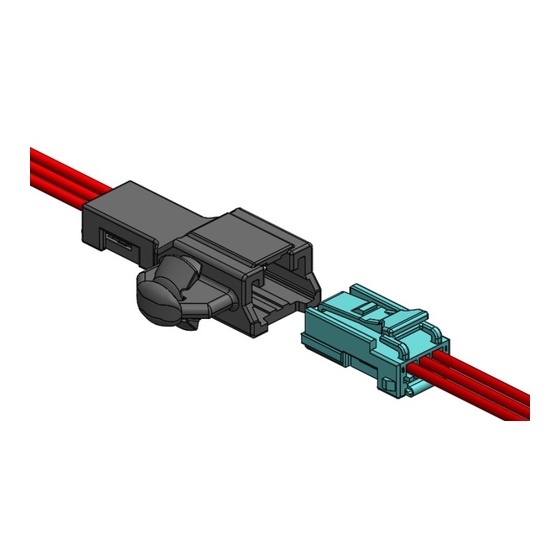
INLINE CONNECTOR
®
Instruction Manual
September 18, 2020
August 18, 2018
July 10, 2018
December 10, 2015
Date
H.Naoi
S.Tanaka
H.Naoi
K.Hanaki
Prepared by
I-PEX Inc.
1 / 22
J.Tateishi
S.Tono
T.Osuga
J.Mukunoki
Checked by
E.Kawabe
T.Osuga
E.Kawabe
T.Endo
Approved by
QKE-DFFDE09-03 REV.8
Advertisement
Table of Contents

Related Manuals for I-PEX ISH


Summary of Contents for I-PEX ISH
- Page 1 J.Tateishi E.Kawabe RS0550 August 18, 2018 S.Tanaka S.Tono T.Osuga RS0511 July 10, 2018 H.Naoi T.Osuga E.Kawabe RS0264 December 10, 2015 K.Hanaki J.Mukunoki T.Endo Rev. Date Prepared by Checked by Approved by Confidential C I-PEX Inc. QKE-DFFDE09-03 REV.8 1 / 22...
-
Page 2: Table Of Contents
Document No. ISH INLINE CONNECTOR Instruction Manual HDM-0006 Contents ・・・・・ Sheet 3 1. Purpose ・・・・・ Sheet 3 2. Applicable items 3. Crimping procedure ・・・・・ Sheet 4 4. Terminal insertion ・・・・・ Sheet 13 5. Secondary lock part installation ・・・・・ Sheet 14 6. -
Page 3: Purpose
ISH INLINE CONNECTOR Instruction Manual HDM-0006 1.Purpose The Manual explains the handling of ISH INLINE CONNECTOR. For female connector, refer to the Handling Manual 【ISH CONNECTOR No.HDM-0002】. 2.Applicable items The Manual is applicable to the items listed below. Name Part No. -
Page 4: Crimping Procedure
Document No. ISH INLINE CONNECTOR Instruction Manual HDM-0006 3.Crimping procedure 3-1.Applicable wires Part No. Applicable Wire wire size:0.3mm ・0.5mm VT002-012 Insulation outer diameter:Φ1.60mm MAX. 3-2.Wire strip length ①Strip the insulation off by 3.0±0.1mm (see Fig.1) ②Check to see that there is no damage to the conductors or insulation, cut off conductors, short conductors and deformed conductors as shown in Fig. - Page 5 Document No. ISH INLINE CONNECTOR Instruction Manual HDM-0006 3-3.Terminal part names Fig 3. Terminal part names 3-4. Crimping requirements (1) Crimp dimension Crimped female terminals must satisfy the crimp dimension specified in Table 1. Table 1. Crimp dimension Insulation Part No.
- Page 6 Document No. ISH INLINE CONNECTOR Instruction Manual HDM-0006 Measuring method for crimp dimension is described below. Use the micrometer shown in Fig.4 for measurement of each part. Fig 4. Micrometer (1)-1. Measuring method for wire barrel crimp height is described below.
- Page 7 Document No. ISH INLINE CONNECTOR Instruction Manual HDM-0006 (1)-3. Measuring method for wire barrel crimp width is described below. To measure the wire barrel crimp width, pinch the side of the wire barrel with a micrometer. (see Fig.7) Secure terminals firmly to obtain accurate measurement.
- Page 8 Document No. ISH INLINE CONNECTOR Instruction Manual HDM-0006 (2) Bottom burrs Burrs produced during crimping process must not extend beyond the bottom surface. (see Fig.9) Bottom surface of terminal Bottom burrs 【No good】 【Good】 Fig 9. Bottom burrs (3) Bellmouth,excess conductors and cut-off tab Bellmouth,excess conductors and cut-off tab must satisfy the dimensions shown in Fig.
- Page 9 Document No. ISH INLINE CONNECTOR Instruction Manual HDM-0006 (4) Unaligned wire barrel ends Unaligned wire barrel ends is 0.1mm MAX..(Fig.11) ※If wire barrel ends are not aligned, resulting in different dimension of excess conductors or bellmouth between the sides,dimensions must be measured on larger side and be satisfied.
- Page 10 Document No. ISH INLINE CONNECTOR Instruction Manual HDM-0006 (6) Terminal twist Terminal twist is 1.2° MAX. from the wire barrel (baseline). (see Fig. 14) Fig 14. Terminal twist (7) Bend up and Bend down Bend up is 1.10mm MAX., and no Bend down respectively, the hight from the wire barrel(baseline) to the terminal box(measurement point).
- Page 11 Document No. ISH INLINE CONNECTOR Instruction Manual HDM-0006 3-5. Defective criteria Terminals with the following conditions are deemed defective. (1) No rear bellmouth Rear bellmouth is not formed. (see Fig.17) Fig 17. No rear bellmouth (2)Insufficient conductors insertion Conductors are insufficiently inserted into the wire barrel. (see Fig.18) Fig 18.
- Page 12 Document No. ISH INLINE CONNECTOR Instruction Manual HDM-0006 (5)Incomplete insulation crimping Strip length is too short and insulation is crimped inside the wire barrel (see Fig.21). Strip length is too long and insulation does not fit completely inside the insulation barrel (see Fig.22) Fig 21.Strip too short...
-
Page 13: Terminal Insertion
Document No. ISH INLINE CONNECTOR Instruction Manual HDM-0006 4.Terminal insertion ①Ensure that the terminal is crimped correctly and there is no damage, deform or dirt present. ②Hold the wire to insert the terminal as shown in Fig.24. ③Insert the terminal into the corresponding corehole of the housing, as deeply as possible, in the orientation as shown in Fig. 24. -
Page 14: Secondary Lock Part Installation
Document No. ISH INLINE CONNECTOR Instruction Manual HDM-0006 5. Secondary lock installation ①After terminal insertion is complete, close the secondary lock part. You will hear audible click when the secondary lock part is engaged properly. (The secondary lock part has two engaging portions. Press down to make sure both portions are engaged) ②Check that the secondary lock part is closed in compretely, i.e. - Page 15 Document No. ISH INLINE CONNECTOR Instruction Manual HDM-0006 ④ Do not use fingertips to install secondary lock parts as shown in Fig. 28. No good Good Good:Use fingerpad No good:Do not use fingertip ⇒Prevent damage by fingernails ⇒Possible damage by fingernails (see Fig.29) Fig.28.
-
Page 16: How To Release Secondary Lock Part
Document No. ISH INLINE CONNECTOR Instruction Manual HDM-0006 6.How to release the secondary lock part ①Place the releasing jig into the secondary lock part taper situated at the bottom of the housing, and move the jig to the direction shown in Fig. 30to release the secondary lock part (release one side at a time). -
Page 17: How To Release Terminals
Document No. ISH INLINE CONNECTOR Instruction Manual HDM-0006 7. How to release terminals (Terminal releasing Jig dimentions see Fig32.) ①Ensure that the secondary lock part have been removed. ②Hold the wire and push in the terminal lightly. Place the terminal releasing jig into the releasing apertures of the housing (see Figs. 31). - Page 18 Document No. ISH INLINE CONNECTOR Instruction Manual HDM-0006 Pivot of releasing jig Direction of release Terminal releasing jig Terminal releasing jig Fig34.Correct orientation of the releasing jig and the housing lance Fig 35.Terminal releasing jig in operation Notes ①Do not pry with the releasing jig or terminals during operation. Check for any deformation or damage on the terminals and the housing after releasing the terminals.
-
Page 19: Mating Of Connector
Document No. ISH INLINE CONNECTOR Instruction Manual HDM-0006 8. Mating of connector ①Once the secondary lock part have been installed, push the connector in the direction of mating until the connector makes an audible click (see Fig. 37). While mating the female connector,please do not touch the lock arm to prevent insufficient mating. -
Page 20: Unmating Of Connector
Document No. ISH INLINE CONNECTOR Instruction Manual HDM-0006 9. Unmating of connector ①Hold the female connector and push it in lightly. ②While holding the female connector in, press down fully on the end of the arm (see Fig. 39). ③Keep pressing the lock down, and pull out the female connector. -
Page 21: Handling Of Product
Document No. ISH INLINE CONNECTOR Instruction Manual HDM-0006 10. Handling of Product 10-1.Conductivity test 10-1-1. Male connector ①When carrying out conductivity test of the male connector, place the probe on the end of the male terminal (Load:0.5N MAX.) If load 0.5N and more, male terminal(s) may be damaged. (see Figs. 41) ②If there is any damage or deformation, do not use the damaged item. - Page 22 Document No. ISH INLINE CONNECTOR Instruction Manual HDM-0006 11.Storage of housings and terminals ①Store housings and terminals in a warehouse which is controlled temperature and humidity. (Recommend : Temperature 27℃MAX. , Humidity 65%MAX.) ②Store housings in a cardboard box. Avoid storing in a way that may cause damage to the boxes, e.g.
Need help?
Do you have a question about the ISH and is the answer not in the manual?
Questions and answers