Advertisement
Quick Links
HDM-0009
Document No.
3
RS0743
2
RS0612
1
RS0550
0
RS0412
Rev.
ECN
Confidential C
ISH
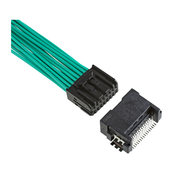
HYBRID CONNECTOR
®
Instruction Manual
September 18, 2020
July 9, 2019
December 18, 2018
November 24, 2017
Date
H.Naoi
S.Tanaka
S.Tanaka
H.Naoi
Prepared by
I-PEX Inc.
1 / 24
J.Tateishi
S.tono
S.tono
T.Osuga
Checked by
E.Kawabe
E.Kawabe
T.Osuga
T.Endo
Approved by
QKE-DFFDE09-03 REV.8
Advertisement

Related Manuals for I-PEX ISH20P


Summary of Contents for I-PEX ISH20P
- Page 1 September 18, 2020 RS0612 July 9, 2019 S.Tanaka S.tono E.Kawabe RS0550 December 18, 2018 S.Tanaka S.tono T.Osuga RS0412 November 24, 2017 H.Naoi T.Osuga T.Endo Rev. Date Prepared by Checked by Approved by Confidential C I-PEX Inc. QKE-DFFDE09-03 REV.8 1 / 24...
- Page 2 Document No. ISH HYBRID CONNECTOR Instruction Manual HDM-0009 目次 ・・・・・ Sheet 3 1. Purpose ・・・・・ Sheet 3 2. Applicable items 3. Crimping procedure ・・・・・ Sheet 4 4. Terminal insertion ・・・・・ Sheet 13 5. Retainer installation ・・・・・ Sheet 14 6. How to release the retainer ・・・・・...
- Page 3 Document No. ISH HYBRID CONNECTOR Instruction Manual HDM-0009 1. Purpose The Manual explains the handling of ISH HYBRID CONNECTOR. 2. Applicable items The Manual is applicable to the items listed below. 品名 端子サイズ 品番 概略図 0.5mm VT001-512 FEMALE TERMINAL 1.5mm VT004-513 MALE CONNECTOR FEMALE CONNECTOR...
- Page 4 Document No. ISH HYBRID CONNECTOR Instruction Manual HDM-0009 3. Crimping procedure 3-1.Applicable wires Table1.Applicable Wire Terminal Part No Applicable Wire Tab Size Wire Size :0.3mm ・0.5mm 0.5mm VT001-512 Insulation Outer Diameter : φ1.60mm MAX. Wire Size :0.5mm 1.5mm VT004-513 Insulation Outer Diameter : φ1.93mm MAX. 3-2.
- Page 5 Document No. ISH HYBRID CONNECTOR Instruction Manual HDM-0009 3-3. Terminal part names Fig 3. Terminal part names 3-4. Crimping requirements (1)Crimp dimension Female Terminals must satisfy the crimp dimension specified in Table 2. Table 2. Crimp dimension Terminal Wire barrel Wire barrel Insulation barrel Insulation barrel...
- Page 6 Document No. ISH HYBRID CONNECTOR Instruction Manual HDM-0009 Measuring method for crimp dimension is described below. Use the micrometer shown in Fig.4 for measurement of each part. Fig 4. Micrometer (1)-1. Measuring method for wire barrel crimp height is described below. To measure the wire barrel crimp height, pinch the top of the wire barrel (winding side) and the bottom of the wire barrel with a micrometer.
- Page 7 Document No. ISH HYBRID CONNECTOR Instruction Manual HDM-0009 (1)-3. Measuring method for wire barrel crimp width is described below. To measure the wire barrel crimp width, pinch the side of the wire barrel with a micrometer. (see Fig.7) Secure terminals firmly to obtain accurate measurement. Micrometer Section Fig 7.
- Page 8 Document No. ISH HYBRID CONNECTOR Instruction Manual HDM-0009 (2) Bottom burrs Burrs produced during crimping process must not extend beyond the bottom surface. (see Fig.9) Bottom surface of terminal Bottom burrs 【Good】 【No good】 Fig 9. Bottom burrs (3) Bellmouth,excess conductors and cut-off tab Bellmouth,excess conductors and cut-off tab must satisfy the dimensions shown in Fig.
- Page 9 Document No. ISH HYBRID CONNECTOR Instruction Manual HDM-0009 (4) Unaligned wire barrel ends Unaligned wire barrel ends is G <0.1mm.(see Fig.11) ※If wire barrel ends are not aligned, resulting in different dimension of excess conductors or bellmouth between the sides, dimensions must be measured on larger side and be satisfied.
- Page 10 Document No. ISH HYBRID CONNECTOR Instruction Manual HDM-0009 (6) Terminal twist Terminal twist is J<1.2° from the wire barrel (baseline). (see Fig. 14) Fig 14. Terminal twist (7) Bend up and Bend down Bend up is [VT001-512 : 1.90mm MAX.] / [ VT004-513 : 2.1mm MAX.], and no Bend down, the hight from the wire barrel(baseline) to the terminal box(measurement point).
- Page 11 Document No. ISH HYBRID CONNECTOR Instruction Manual HDM-0009 3-5. Defective criteria Terminals with the following conditions are deemed defective. (1) No rear bellmouth Rear bellmouth is not formed. (see Fig.17) Fig 17. No rear bellmouth (2)Insufficient conductors insertion Conductors are insufficiently inserted into the wire barrel. (see Fig.18) Fig 18.
- Page 12 Document No. ISH HYBRID CONNECTOR Instruction Manual HDM-0009 ※Description of faults:Excessive conductors out & Incomplete conductors crimping. Please make sure there is no excessive conductors out and incomplete conductors crimping. When the retainer is inserted, excess conductors could be caught in the gap between the female housing and the retainer.
- Page 13 Document No. ISH HYBRID CONNECTOR Instruction Manual HDM-0009 4. Terminal insertion ①Ensure that the terminal is crimped correctly and there is no damage, deform or dirt present. ②Hold the wire to insert the terminal as shown in Fig.25. ③Insert the terminal into the corresponding corehole of the housing, as deeply as possible, in the orientation as shown in Fig.
- Page 14 Document No. ISH HYBRID CONNECTOR Instruction Manual HDM-0009 5. Retainer installation ①Make sure that both ends of the retainer protrude from bottom of the female housing surface before inserting the female terminal into the female housing. If one end or both ends of retainer are engaged with the female housing, pay attention not to deform the female housing, and release the retainer by the method in 6(sheet 16).
- Page 15 Document No. ISH HYBRID CONNECTOR Instruction Manual HDM-0009 6.How to release the retainer ①Insert a screwdriver with a width of 1.0mm to 1.5mm into the releasing jig aperture (2 places) in the bottom surface of the female housing, and push out the retainer. (see Fig.30). Releasing jig aperture Direction of release Fig 30.
- Page 16 Document No. ISH HYBRID CONNECTOR Instruction Manual HDM-0009 7.How to release female terminals (※Use the exclusive jig, or a jig of which tip shape dimension is corresponded to Fig33.) ①Ensure that the rear holder and the retainer have been removed. ②Hold the wire and push in the female terminal lightly.
- Page 17 Document No. ISH HYBRID CONNECTOR Instruction Manual HDM-0009 Table4.Female Terminal releasing jig Part No Terminal Female Terminal Part No. Terminal releasing jig Part No. Tab Size 0.5mm VT001-512 AP0004-01-005 1.5mm VT004-513 AP0037-01-001 DETAIL A DETAIL B Dimensions Terminal Female Terminal Terminal releasing jig Tab Size Part No.
- Page 18 Document No. ISH HYBRID CONNECTOR Instruction Manual HDM-0009 Notes ①Do not pry with the releasing jig or female terminals during operation. Check for any deformation or damage on the female terminals and the housing after releasing the femele terminals. (see Fig.36) ②Do not continue applying force once the lance has reached the ceiling, or the ceiling will be deformed or releasing jig may be damaged by excessive force.
-
Page 19: Rear Cover
Document No. ISH HYBRID CONNECTOR Instruction Manual HDM-0009 8. Rear cover installation (Rear cover : Individual part) ① Verify that pin numbers of the female housing and the rear cover are the same and also the female housing corresponds to rear cover. In addition, check that there is no damage, deform or dirt present. - Page 20 Document No. ISH HYBRID CONNECTOR Instruction Manual HDM-0009 9. Mating of connector ①Push the female connector that has been installed the retainer in the direction of mating until makes an audible click (see Fig. 41). While mating the female connector, please do not touch the lock arm to prevent insufficient mating. ②After that, pull the female connector lightly to check that the female connector is locked.
- Page 21 Document No. ISH HYBRID CONNECTOR Instruction Manual HDM-0009 10. Unmating of connector ①Hold the female connector and push it in lightly. ②While holding the female connector in, press down fully on the end of the arm (see Fig. 43). ③Keep pressing the lock down, and pull out the female connector. ②Press down on the edge Direction of pressing Lock arm...
- Page 22 Document No. ISH HYBRID CONNECTOR Instruction Manual HDM-0009 11-1-2.Female Connector ①Do not recommend to perform a conductivity test using the mated male connector. If the same male connector is used for conductivity test, the connectors are repeatedly mated and unmated, and the male terminal could be bent. These may cause of the female terminal spring deformation, or the contact failure caused by adhesion the particles of friction according to excessive insertion and removal actions.
- Page 23 Procedurees Female Housing Part No. Female Terminal Part No. Jig Part No. Procedures detailed on VT001-512 AP0004-01-005 (0.5mm Female Terminal) Female Terminal ISH20P HIBRID:V0072-020B-111 Releasing Terminal sheet 15~17 releasing jig V0072-020B-112 VT004-513 AP0037-01-001 (1.5mm Female Terminal) Confidential C 23 / 24...
- Page 24 ⑧Do not insert any terminals into housing other than those specified. ⑨Follow this Manual for using the products. Do not use in any way other than instructed. 15. Contact Tokyo office Sales Dept. I-PEX Inc. TEL: 03-5479-7410 FAX: 03-5479-7411 Confidential C 24 / 24...
Need help?
Do you have a question about the ISH20P and is the answer not in the manual?
Questions and answers