Advertisement
Quick Links
WARNING
WARNING
1.0
GENERAL INFORMATION
1.1
REQUIRED TOOLS
Hex Keys
3/32", 3/16", and 7/32"
Ball End Hex Key
5/16"
Molykote #112 high temperature
silicone grease
1.2
THREADED JOINTS
Threaded joints have been secured at the factory using Loctite brand thread locking adhesive #263 (red) or #242 (blue).
• Disassembly of joints where #263 Loctite is used requires a minimal application of heat with a oxyacetylene torch to break the bond.
• The threads should be heated to approximately 450°F. Excessive heat application will cause damage to adjacent seals and labels.
• Replacement parts must be reinstalled using either Loctite #271 or #242 where specified, or equivalent. Small vials of Loctite for
field service are available. Order part # V5010 (#271 LOCTITE MINI DISPENSER) or VSA-125 (LOCTITE BLUE #24205 MINI
DISPENSER).
• Threads must be clean, dry, and free of grease or oil when applying Loctite.
• Allow Loctite to set up for at least one hour before using or subjecting to water.
1.3
LUBRICANTS
If parts are disassembled in an area where O-rings are present, re-assemble using Molykote #112 High Performance Silicone Grease on
all O-rings and surfaces that the O-rings contact. If nozzle is not disassembled refer to the field lubrication procedure in the nozzle
manual.
CAUTION
1.4
LABEL REPLACEMENT
If labels become damaged, remove old labels with razor knife. Remove adhesive with acetone or methyl ethyl ketone. Surface must be
clean, dry, and free from grease. Remove protective backing and carefully apply new label.
TASK FORCE TIPS LLC
MADE IN USA · tft.com
©Copyright Task Force Tips LLC 1995-2020
Maintenance and Service Procedure
Service technicians bear responsibility for ensuring use of appropriate protective clothing and
equipment. The chosen protective clothing and equipment must provide protection from potential
hazards users may encounter while servicing equipment. Requirements for protective clothing and
equipment are determined by the Authority Having Jurisdiction (AHJ).
After any maintenance or service, equipment must be inspected and tested for proper operation
and function per NFPA 1962 test procedures and the FLOW CHARACTERISTICS and OPERATION
and INSPECTION CHECKLIST in the nozzle's operator manual.
This publication is intended for those who prefer to perform service on their own equipment.
Factory service is available and repair time seldom exceeds one day in our facility. Factory serviced
nozzles are repaired by experienced technicians, fully tested, and promptly returned functioning to
original specifications. Task Force Tips assumes no liability for damage to equipment or injury to
personnel that is a result of user service.
Tools for
General Service
®
Loctite
locker or equivalent
Oxyacetylene Torch
Razor Knife
Aerosol lubricants contain solvents that can swell O-Rings if applied in excess. The swelling can
inhibit smooth operation of the moving parts. When used in moderation, as directed, the solvents
quickly evaporate without adversely swelling the O-Rings.
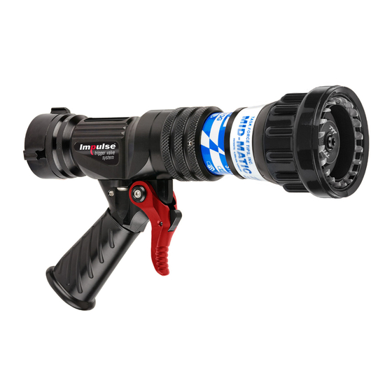
Ultimatic 125 Nozzle Series
#271 and #242 thread
1
Tools for
FRONT END Service
Strap Wrench
Vise with padded jaws
Ultimatic Shaper Removal Tool
optional (TFT part# TB502-ST)
3701 Innovation Way, Valparaiso, IN 46383-9327 USA
800-348-2686 · 219-462-6161 · Fax 219-464-7155
LIB-020 April 21, 2021 Rev04
Advertisement

Related Manuals for Task Force Tips 125 Nozzle Series


Summary of Contents for Task Force Tips 125 Nozzle Series
- Page 1 Factory service is available and repair time seldom exceeds one day in our facility. Factory serviced nozzles are repaired by experienced technicians, fully tested, and promptly returned functioning to original specifications. Task Force Tips assumes no liability for damage to equipment or injury to personnel that is a result of user service.
- Page 2 1. Heat the two SET SCREWS (14) and remove with a 3/32” hex key. 2. Unscrew the front end from the valve assembly. 3. To reassemble see section on VALVE SHUTOFF ADJUSTMENT. ©Copyright Task Force Tips LLC 1995-2020 LIB-020 April 21, 2021 Rev04...
- Page 3 (see section 4.3.3) and backing off 1/12-turn. The valve can be returned to normal adjustment for complete shut off during warm weather by following the procedure in the previous section. ©Copyright Task Force Tips LLC 1995-2020 LIB-020 April 21, 2021 Rev04...
- Page 4 4. With the SHAPER GUIDE fully forward in the straight stream position, apply Loctite #271 to male thread on SHAPER GUIDE (30). Start shaper onto SHAPER GUIDE threads. 5. Screw down shaper until threads bottom out. ©Copyright Task Force Tips LLC 1995-2020 LIB-020 April 21, 2021 Rev04...
- Page 5 SIZE PART # PART # SIZE PART # PART # 38 mm B679 1.5" B686 VO-128 B685 H686 VO-134 B689 B687 2.5" 55 mm H689 65 mm VO-143 B688 ©Copyright Task Force Tips LLC 1995-2020 LIB-020 April 21, 2021 Rev04...
- Page 6 24 3/8-24 x 1/2" SOCKET CAP VT37-24SH500 SCREW 25 DUAL MOUNTING PLATE B695 SLIDE VALVE (2 PER SIDE) 26 TIP ONLY BASE B665 55 WASHER VM4901 (2) NOZZLES REQUIRED GRIPS ©Copyright Task Force Tips LLC 1995-2020 LIB-020 April 21, 2021 Rev04...
- Page 7 B745-F 52 QUAD-RING-4225 VOQ-4225 NAME LABEL, 75 PSI B745F 53 1/8 NYLON BALL V2135 BARREL ASSEMBLY-100 PSI (7 BAR) B810-KIT SHAPER WITH BUMPER B500 DRY CHEM VALVE PLUG B592 ©Copyright Task Force Tips LLC 1995-2020 LIB-020 April 21, 2021 Rev04...
- Page 8 For questions regarding troubleshooting, parts, or repair, contact your local dealer or TFT’s service department. TASK FORCE TIPS LLC 3701 Innovation Way, Valparaiso, IN 46383-9327 USA 800-348-2686 · 219-462-6161 · Fax 219-464-7155 MADE IN USA · tft.com ©Copyright Task Force Tips LLC 1995-2020 LIB-020 April 21, 2021 Rev04...
Need help?
Do you have a question about the 125 Nozzle Series and is the answer not in the manual?
Questions and answers