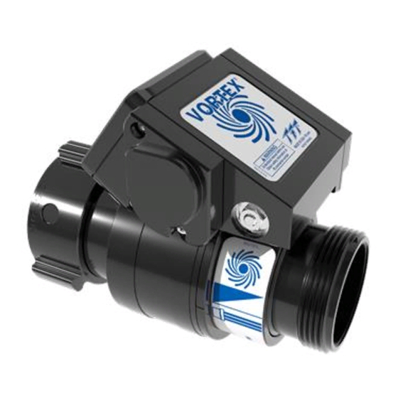
Table of Contents
Advertisement
Quick Links
INSTRUCTIONS FOR INSTALLATION, SAFE OPERATION AND MAINTENANCE
WARNING
This instruction manual is intended to familiarize fi refi ghters and maintenance personnel with the operation, servicing and
safety procedures associated with the VORTEX fi re fi ghting nozzles.
This manual should be kept available to all operating and maintenance personnel.
TASK FORCE TIPS LLC
MADE IN USA • tft.com
©Copyright Task Force Tips LLC 2018 - 2019
MANUAL: VORTEX
Understand manual before use. Operation of this device without understanding the manual
and receiving proper training is a misuse of this equipment. Obtain safety information at
tft.com/serial-number
VORTEX 2 ER
MOUNTED NOZZLES
VORTEX 2
VORTEX 6 ER
3701 Innovation Way, Valparaiso, IN 46383-9327 USA
800-348-2686 • 219-462-6161 • Fax 219-464-7155
MONITOR
®
LIS-045 April 22, 2019 Rev01
Advertisement
Table of Contents

Subscribe to Our Youtube Channel
Summary of Contents for Task Force Tips VORTEX 2 ER
- Page 1 VORTEX 2 VORTEX 6 ER TASK FORCE TIPS LLC 3701 Innovation Way, Valparaiso, IN 46383-9327 USA 800-348-2686 • 219-462-6161 • Fax 219-464-7155 MADE IN USA • tft.com ©Copyright Task Force Tips LLC 2018 - 2019 LIS-045 April 22, 2019 Rev01...
- Page 2 6. Failure to follow these guidelines may result in death, burns or other severe injury. Fire and Emergency Manufacturers and Service Association FEMSA P.O. Box 147, Lynnfi eld, MA 01940 • www.FEMSA.org ©Copyright Task Force Tips LLC 2018 - 2019 LIS-045 April 22, 2019 Rev01...
-
Page 3: Table Of Contents
6.0 OPERATION ......................................10 7.0 USE WITH FOAM ......................................11 8.0 USE OF NOZZLES ....................................11 9.0 EXPLODED VIEWS AND PARTS LISTS ..............................12 9.1 VORTEX 2 & VORTEX 2 ER NOZZLE ASSEMBLY 9.2 VORTEX 6 ER NOZZLE ASSEMBLY 10.0 MAINTENANCE ......................................14 10.1 FIELD LUBRICATION 10.2 SERVICE TESTING... -
Page 4: Meaning Of Safety Signal Words
Maximum fl ow and pressure is shown in Figure 3.1.1 Operating Envelope. Damage or injury may CAUTION result if the monitor is operated beyond these limits. ©Copyright Task Force Tips LLC 2018 - 2019 LIS-045 April 22, 2019 Rev01... -
Page 5: General Information
VORTEX 2 Figure 3.1.1 VORTEX 2 ER and VORTEX 2 Part Identifi cation and Terms 3.1.2 VORTEX 6 ER PART IDENTIFICATION AND TERMS VORTEX and VORTEX ER models are confi gured with a 6”NH female fi xed coupling and 6”NH male threads on the outlet for use with connecting to Tsunami Stacked Tips. -
Page 6: Specifications
Use with saltwater is permissible provided nozzle is thoroughly cleaned with fresh water after each use. The service life of the nozzle may be shortened due to the eff ects of corrosion and is not covered under warranty. ©Copyright Task Force Tips LLC 2018 - 2019 LIS-045 April 22, 2019 Rev01... -
Page 7: Flow Characteristics And Charts
1363 1571 1756 1503 1647 1900 2127 1790 1961 2264 2529 2434 2669 3081 3445 3180 3486 4024 4497 Figure 4.1B 2.5” (65mm) Stacked Tip Flow Tables ©Copyright Task Force Tips LLC 2018 - 2019 LIS-045 April 22, 2019 Rev01... -
Page 8: Vortex 6 Er Flow Characteristics And Charts
13780 12720 13930 16090 17980 1140 16090 17640 20360 1160 22790 1450 20890 22860 1120 26420 1500 29520 1880 Figure 4.2B 6” (157mm) Stacked Tip Flow Tables ©Copyright Task Force Tips LLC 2018 - 2019 LIS-045 April 22, 2019 Rev01... -
Page 9: Installation
5.0 INSTALLATION 5.1 VORTEX 2 & 2 ER INSTALLATION The VORTEX 2 & VORTEX 2 ER is intended to be installed on the outlet of a monitor and paired with stacked tips or smooth bores. 1.5” 1.25” 1” (38mm) (32mm) -
Page 10: Operation
Exceeding 60 in-lb (6.8 N m) can damage the actuator. Electric remote nozzle has fi nger pinch points. Keep fi ngers away from nozzle when using electric CAUTION control. ©Copyright Task Force Tips LLC 2018 - 2019 LIS-045 April 22, 2019 Rev01... -
Page 11: Use With Foam
This manual is not intended to act as a training guide for safe fi reground tactics and operations. For additional information visit tft.com or contact customer service at 800-348-2686. ©Copyright Task Force Tips LLC 2018 - 2019 LIS-045 April 22, 2019 Rev01... -
Page 12: Exploded Views And Parts Lists
9.0 EXPLODED VIEW AND PARTS LIST 9.1 VORTEX 2 & VORTEX 2 ER NOZZLE ASSEMBLY ITEM DESCRIPTION QTY PART # GASKET - 2.5" HOSE COUPLING V3190 COUPLING 2.5" M307* BALL 3/16" STAINLESS 48 V2120 1/4-28 X 1/2 SOCKET SET SCREW CUP POINT VT25-28SS500 2.5"... -
Page 13: Vortex 6 Er Nozzle Assembly
SVX100 DRIVE RING SVX115 1/2-20 X 3/8 SOCKET SET SCREW CUP POINT VT50-20SS375 BALL 7/16" TORLON 51 VB437TO RING LABEL: VORTEX SVX131L VORTEX 6 ER ACTUATOR Y7200 ©Copyright Task Force Tips LLC 2018 - 2019 LIS-045 April 22, 2019 Rev01... -
Page 14: Maintenance
Any returns should include a note as to the nature of the problem and whom to reach in case of questions. Repair parts and service procedures are available for those wishing to perform their own repairs. Task Force Tips assumes no liability for damage to equipment or injury to personnel that is a result of user service. -
Page 15: Warranty
11.0 WARRANTY Task Force Tips LLC, 3701 Innovation Way, Valparaiso, Indiana 46383-9327 USA (“TFT”) warrants to the original purchaser of its nozzles (“equipment”), and to anyone to whom it is transferred, that the equipment shall be free from defects in material and workmanship during the fi... -
Page 16: Operation And Inspection Checklist
TASK FORCE TIPS LLC 3701 Innovation Way, Valparaiso, IN 46383-9327 USA 800-348-2686 • 219-462-6161 • Fax 219-464-7155 MADE IN USA • tft.com ©Copyright Task Force Tips LLC 2018 - 2019 LIS-045 April 22, 2019 Rev01...


Need help?
Do you have a question about the VORTEX 2 ER and is the answer not in the manual?
Questions and answers