Vega VEGAPULS 61 Operating Instructions Manual
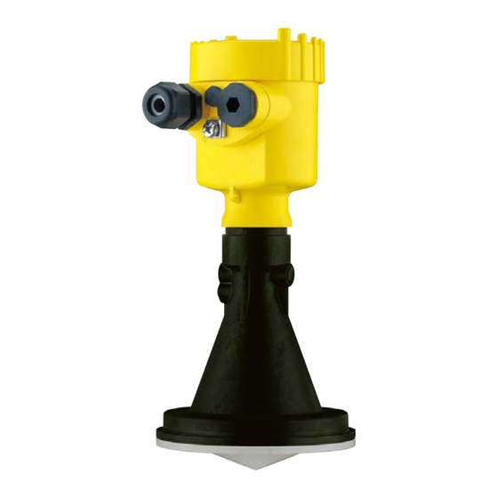
Radar sensor for continuous level measurement of liquids
Hide thumbs
Also See for VEGAPULS 61:
- Operating instructions manual (100 pages) ,
- Quick setup manual (24 pages) ,
- Safety manual (16 pages)

Subscribe to Our Youtube Channel
Related Manuals for Vega VEGAPULS 61


Summary of Contents for Vega VEGAPULS 61
- Page 1 Operating Instructions Radar sensor for continuous level measurement of liquids VEGAPULS 61 Foundation Fieldbus Approval according to LPR radio standard Document ID: 41716...
-
Page 2: Table Of Contents
Measured value indication - Selection of national language ........... 35 Parameter adjustment ....................36 Saving the parameterisation data ................... 53 Setup with PACTware ......................54 Connect the PC ......................54 Parameter adjustment ....................54 Saving the parameterisation data ................... 55 VEGAPULS 61 • Foundation Fieldbus... - Page 3 11.5 Industrial property rights ....................92 11.6 Trademark ........................92 Safety instructions for Ex areas Take note of the Ex specific safety instructions for Ex applications. These instructions are attached as documents to each instrument with Ex approval and are part of the operating instructions. Editing status: 2018-12-19 VEGAPULS 61 • Foundation Fieldbus...
-
Page 4: About This Document
Symbols used Document ID This symbol on the front page of this instruction refers to the Docu- ment ID. By entering the Document ID on www.vega.com you will reach the document download. Information, tip, note This symbol indicates helpful additional information. -
Page 5: For Your Safety
During work on and with the device, the required personal protective equipment must always be worn. Appropriate use VEGAPULS 61 is a sensor for continuous level measurement. You can find detailed information about the area of application in chapter "Product description". Operational reliability is ensured only if the instrument is properly used according to the specifications in the operating instructions manual as well as possible supplementary instructions. -
Page 6: Eu Conformity
Use is also approved in EFTA countries, provided the respective standards have been implemented. For operation inside of closed vessels, points a to f in annex E of EN 302372 must be fulfilled. For operation outside of closed vessels, the following conditions must be fulfilled: • The installation must be carried out by trained qualified personnel VEGAPULS 61 • Foundation Fieldbus... -
Page 7: Installation And Operation In The Usa And Canada
That is why we have introduced an environment management system with the goal of continuously improving company environmental pro- tection. The environment management system is certified according to DIN EN ISO 14001. Please help us fulfil this obligation by observing the environmental instructions in this manual: • Chapter "Packaging, transport and storage" • Chapter "Disposal" VEGAPULS 61 • Foundation Fieldbus... -
Page 8: Product Description
Go to "www.vega.com", "Search". Enter the serial number. Alternatively, you can access the data via your smartphone: • Download the VEGA Tools app from the "Apple App Store" or the "Google Play Store" • Scan the Data Matrix code on the type label of the instrument or •... -
Page 9: Principle Of Operation
Principle of operation Application area The VEGAPULS 61 is a radar sensor for continuous level measure- ment of liquids under simple process conditions. The instrument is ideal also for all applications in the water and waste water industry. It is particularly suitable for level measurement in water treatment, in pump stations as well as storm water overflow tanks, for flow measurement in open flumes and for gauge measurement. -
Page 10: Accessories And Replacement Parts
PACTware with VEGA-DTM is required. You can find further information in the operating instructions "Interface adapter VEGACONNECT" (Document-ID 32628). VEGADIS 81 The VEGADIS 81 is an external display and adjustment unit for VEGA plics sensors. ® For sensors with double chamber housing the interface adapter "VEGADIS adapter"... - Page 11 VEGAPULS series 60" (Document-ID 36801). Supplementary elec- The supplementary electronics is a replacement part for sensors with tronics for Foundation Foundation Fieldbus and double chamber housing. Fieldbus You can find further information in the operating instructions "Supple- mentary electronics for Foundation Fieldbus" (Document-ID 45111). VEGAPULS 61 • Foundation Fieldbus...
-
Page 12: Mounting
Chemical properties of the medium • Abrasion and mechanical influences You can find detailed information on the process conditions in chapter "Technical data" as well as on the type label. Suitability for the ambient The instrument is suitable for standard and extended ambient condi- conditions tions acc. to IEC/EN 61010-1. VEGAPULS 61 • Foundation Fieldbus... -
Page 13: Collar Or Adapter Flange
There are two ways to screw the strap onto the sensor. Depending on the selected version, the sensors can be swivelled in the strap as follows: • Single chamber housing – Angle of inclination 180°, infinitely variable – Angle of inclination in three steps 0°, 90° and 180° VEGAPULS 61 • Foundation Fieldbus... -
Page 14: Mounting Instructions
The emitted radar impulses of the radar sensor are electromagnetic waves. The polarisation is the direction of the electrical share. With radar sensors, the polarisation can be used to reduce the effect of false echoes considerably by turning the instrument in the connection flange or mounting boss. The position of the polarisation is marked on the instrument. VEGAPULS 61 • Foundation Fieldbus... - Page 15 Fig. 6: Mounting of the radar sensor on round vessel tops In vessels with conical bottom it can be advantageous to mount the sensor in the centre of the vessel, as measurement is then possible down to the bottom. VEGAPULS 61 • Foundation Fieldbus...
- Page 16 Fig. 8: Mounting of the radar sensor with inflowing medium Socket with plastic horn A corresponding collar flange for DN 80 (ASME 3" or JIS 80) as well antenna as a suitable adapter flange are available for mounting VEGAPULS With the housing versions plastic, aluminium single chamber and stainless steel, the collar flange can be placed directly over the hous- ing. With the aluminium double chamber housing, retroactive mount- ing in this way is not possible - the mounting type must be specified with the order. VEGAPULS 61 • Foundation Fieldbus...
- Page 17 ≤ 500 mm ≤ 19.7 in Socket diameter d Socket length h 3" ≤ 11.8 in 4" ≤ 15.8 in 6" ≤ 19.7 in Sensor orientation In liquids, direct the sensor as perpendicular as possible to the prod- uct surface to achieve optimum measurement results. VEGAPULS 61 • Foundation Fieldbus...
- Page 18 Fig. 12: Cover flat, large-area profiles with deflectors If there are agitators in the vessel, a false signal suppression should Agitators be carried out with the agitators in motion. This ensures that the interfering reflections from the agitators are saved with the blades in different positions. VEGAPULS 61 • Foundation Fieldbus...
-
Page 19: Measurement Setup - Pipes
Under these prerequisites, the measurement of products with low dielectric values (ε value ≤ 1.6) is possible. Note the following illustrations and instructions for measurement in a surge pipe. Information: Measurement in a surge pipe is not recommended for extremely adhesive products. VEGAPULS 61 • Foundation Fieldbus... - Page 20 4 Mounting Configuration surge pipe 100% Fig. 14: Configuration surge pipe VEGAPULS 61 Radar sensor Polarisation marking Thread or flange on the instrument Vent hole Holes Welding connection through U-profile Ball valve with complete opening Surge pipe end Reflector sheet 10 Fastening of the surge pipe...
- Page 21 • A false signal suppression with the installed sensor is recom- mended but not mandatory • The measurement through a ball valve with unrestricted channel is possible VEGAPULS 61 • Foundation Fieldbus...
- Page 22 • An extension via welding neck flanges or pipe collars is not recom- mended. Measurement in the An alternative to measurement in a surge pipe is measurement in a bypass tube bypass tube outside of the vessel. VEGAPULS 61 • Foundation Fieldbus...
- Page 23 • A false signal suppression with the installed sensor is recom- mended but not mandatory • The measurement through a ball valve with unrestricted channel is possible VEGAPULS 61 • Foundation Fieldbus...
-
Page 24: Measurement Setup - Flow
In general, the following points must be observed: • Install the sensor on the headwater side • Installation in the centre of the flume and vertical to the liquid surface • Distance to the overfall orifice • Distance of orifice opening above ground • Min. distance of the orifice opening to tailwater • Min. distance of the sensor to max. storage level VEGAPULS 61 • Foundation Fieldbus... - Page 25 Position sensor Venturi flume In general, the following points must be observed: • Installation of the sensor at the inlet side • Installation in the centre of the flume and vertical to the liquid surface • Distance to the Venturi flume • Min. distance of the sensor to max. storage level VEGAPULS 61 • Foundation Fieldbus...
-
Page 26: Connecting To The Bus System
Max. torque for all housings, see chapter "Technical data". Cable screening and Make sure that the cable screen and grounding are carried out ac- grounding cording to Fieldbus specification. We recommend to connect the cable screening to ground potential on both ends. VEGAPULS 61 • Foundation Fieldbus... -
Page 27: Connecting
6. Insert the wire ends into the terminals according to the wiring plan Information: Solid cores as well as flexible cores with wire end sleeves are insert- ed directly into the terminal openings. In case of flexible cores without end sleeves, press the terminal from above with a small screwdriver, the terminal opening is then free. When the screwdriver is released, the terminal closes again. VEGAPULS 61 • Foundation Fieldbus... -
Page 28: Wiring Plan, Single Chamber Housing
Voltage supply, signal output Contact pins for the display and adjustment module or interface adapter Simulation switch ("1" = mode for simulation release) For external display and adjustment unit Ground terminal for connection of the cable screening VEGAPULS 61 • Foundation Fieldbus... -
Page 29: Wiring Plan, Double Chamber Housing
For external display and adjustment unit Ground terminal for connection of the cable screening Information: Parallel use of an external display and adjustment unit and a display and adjustment module in the connection compartment is not sup- ported. VEGAPULS 61 • Foundation Fieldbus... -
Page 30: Wiring Plan, Ex-D-Ia Double Chamber Housing
Fig. 25: Top view of the plug connector Pin 1 Pin 2 Pin 3 Pin 4 Contact pin Colour, connection ca- Terminal, electronics ble in the sensor module Pin 1 Brown VEGAPULS 61 • Foundation Fieldbus... -
Page 31: Double Chamber Housing With Vegadis-Adapter
Fig. 27: View to the plug connector M12 x 1 Pin 1 Pin 2 Pin 3 Pin 4 Contact pin Colour, connection ca- Terminal, electronics ble in the sensor module Pin 1 Brown Pin 2 White Pin 3 Blue Pin 4 Black VEGAPULS 61 • Foundation Fieldbus... -
Page 32: Wiring Plan - Version Ip 66/Ip 68, 1 Bar
Brown (+) and blue (-) to power supply or to the processing system Shielding Switch-on phase After VEGAPULS 61 is connected to the bus system, the instrument carries out a self-test for approx. 30 seconds. The following steps are carried out: •... -
Page 33: Set Up With The Display And Adjustment Module
The display and adjustment module is powered by the sensor, an ad- ditional connection is not necessary. Fig. 29: Installing the display and adjustment module in the electronics compart- ment of the single chamber housing VEGAPULS 61 • Foundation Fieldbus... -
Page 34: Adjustment System
LC display Adjustment keys • Key functions [OK] key: – Move to the menu overview – Confirm selected menu – Edit parameter – Save value • [->] key: – Change measured value presentation – Select list entry VEGAPULS 61 • Foundation Fieldbus... -
Page 35: Measured Value Indication - Selection Of National Language
Approx. 60 minutes after the last pressing of a key, an automatic reset to measured value indication is triggered. Any values not confirmed with [OK] will not be saved. Measured value indication - Selection of national language Measured value indica- With the [->] key you move between three different indication modes. tion VEGAPULS 61 • Foundation Fieldbus... -
Page 36: Parameter Adjustment
In the main menu item "Setup", the individual submenu items should be selected one after the other and provided with the correct parameters to ensure optimum adjustment of the measurement. The procedure is described in the following. VEGAPULS 61 • Foundation Fieldbus... - Page 37 The following options are available when "Liquid" is selected: The selection "Standpipe" opens a new window in which the inner diameter of the applied standpipe is entered. Following the characteristics of the applications and the metrological features of the sensor are described. VEGAPULS 61 • Foundation Fieldbus...
- Page 38 – Max. requirement on measurement accuracy from 95 % • Properties, sensor: – Low sensitivity to sporadic false echoes – Stable and reliable measured values through averaging – High measurement accuracy – False signal suppression required VEGAPULS 61 • Foundation Fieldbus...
- Page 39 – Entering the tube inside diameter takes the running time shift into consideration – Echo detection sensitivity reduced Bypass: • Medium speed: – Fast up to slow filling with short up to long bypass tube possible – Often the level is hold via a control facility • Vessel: – Lateral outlets and inlets – Joins like flanges, weld joints VEGAPULS 61 • Foundation Fieldbus...
- Page 40 – Spiders and insects build nests in the antennas – Floating material and animals sporadically appear on water surface • Properties, sensor: – Stable and reliable measured values through frequent averag- – Insensitive in the close range VEGAPULS 61 • Foundation Fieldbus...
- Page 41 Setup - Vessel height, Through this selection the operating range of the sensor is adapted measuring range to the vessel height, which considerably increases measurement reli- ability under different basic conditions. The min. adjustment must be carried out independently of this. VEGAPULS 61 • Foundation Fieldbus...
- Page 42 100% Fig. 33: Parameterisation example, Min./max. adjustment Min. level = max. measuring distance Max. level = min. measuring distance Reference plane If these values are not known, an adjustment with the distances of e.g. 10 % and 90 % is possible. Starting point for these distance specifica- VEGAPULS 61 • Foundation Fieldbus...
- Page 43 5. Save settings with [OK] and move with [ESC] and [->] to the max. adjustment. Setup - Max. adjustment Proceed as follows: 1. Select with [->] the menu item Max. adjustment and confirm with [OK]. 2. Prepare the percentage value for editing with [OK] and set the cursor to the requested position with [->]. VEGAPULS 61 • Foundation Fieldbus...
- Page 44 In delivery status, the PIN is "0000". Display - Language This menu item enables the setting of the requested national lan- guage. In delivery status, the sensor is set to the ordered national language. VEGAPULS 61 • Foundation Fieldbus...
- Page 45 The respective min. and max. measured values of the electronics tem- temperature perature are saved in the sensor. These values as well as the current temperature value are displayed in the menu item "Peak values". VEGAPULS 61 • Foundation Fieldbus...
- Page 46 5. Set the requested numerical value with [+] and [->] 6. Push [OK] Note: During simulation, the simulated value is output as Profibus PA signal. How to interrupt the simulation: → Push [ESC] Information: The simulation is automatically terminated 10 minutes after the last pressing of a key. VEGAPULS 61 • Foundation Fieldbus...
- Page 47 Additional adjustments Additional adjustments - In this menu item you select the measured variable of the system and Instrument units the temperature unit. Additional adjustments - In this menu item, you define the unit of the Secondary Values 2 Unit SV2 (SV2): VEGAPULS 61 • Foundation Fieldbus...
- Page 48 (too large) value is entered, the existing level will be saved as a false signal. The level would then no longer be detectable in this area. If a false signal suppression has already been saved in the sensor, the following menu window appears when selecting "False signal suppression": VEGAPULS 61 • Foundation Fieldbus...
- Page 49 Additional settings - PIN Entering a 4-digit PIN protects the sensor data against unauthorized access and unintentional modification. In this menu item, the PIN is displayed or edited and changed. However, this menu item is only available if adjustment is enabled in the menu "Setup". VEGAPULS 61 • Foundation Fieldbus...
- Page 50 • Peak values, measured value: Resets the measured min. and max. distances to the current measured value. Select the requested reset function [->] and confirm with [OK]. The following table shows the default values of VEGAPULS 61: VEGAPULS 61 • Foundation Fieldbus...
- Page 51 From there, they can be written into one or more sen- sors or kept as backup for a possible sensor exchange. VEGAPULS 61 • Foundation Fieldbus...
- Page 52 Info - Device ID In this menu item, the FF Device ID of the instrument will be dis- played: Instrument features In this menu item, the features of the sensor such as approval, pro- cess fitting, seal, measuring range, electronics, housing and others are displayed. VEGAPULS 61 • Foundation Fieldbus...
-
Page 53: Saving The Parameterisation Data
In the display and adjust- If the instrument is equipped with a display and adjustment module, ment module the parameter adjustment data can be saved therein. The procedure is described in menu item "Copy device settings". VEGAPULS 61 • Foundation Fieldbus... -
Page 54: Setup With Pactware
Further setup steps are described in the operating instructions manu- al "DTM Collection/PACTware" attached to each DTM Collection and which can also be downloaded from the Internet. Detailed descrip- tions are available in the online help of PACTware and the DTMs. VEGAPULS 61 • Foundation Fieldbus... -
Page 55: Saving The Parameterisation Data
The standard version is available as a download under www.vega.com/downloads and "Software". The full version is avail- able on CD from the agency serving you. Saving the parameterisation data We recommend documenting or saving the parameterisation data via PACTware. -
Page 56: Set Up With Other Systems
This software is updated via the Internet and new EDDs are automatically accepted into the device catalogue of this software after they are released by the manufacturer. They can then be transferred to a Field Communicator. VEGAPULS 61 • Foundation Fieldbus... -
Page 57: Diagnosis, Asset Management And Service
The data are read out via a PC with PACTware/DTM or the control system with EDD. The echo curves are stored with date and time and the corresponding Echo curve memory echo data. The memory is divided into two sections: VEGAPULS 61 • Foundation Fieldbus... -
Page 58: Asset Management Function
(for example during simulation). This status message is inactive by default. It can be activated by the user via PACTware/DTM or EDD. Out of specification: The measured value is unreliable because an instrument specification was exceeded (e.g. electronics temperature). VEGAPULS 61 • Foundation Fieldbus... - Page 59 Error in the cali- • Error in the EEPROM bration • • F261 Error during setup Repeat setup Bit 9 • • False signal suppression faulty Repeat reset Error in the config- • Error when carrying out a reset uration VEGAPULS 61 • Foundation Fieldbus...
- Page 60 Bit 14 • Send instrument for repair Error in the non- active linearisation table • • M502 Hardware error EEPROM Exchanging the electronics Bit 15 • Send instrument for repair Error in the diag- nostics memory VEGAPULS 61 • Foundation Fieldbus...
-
Page 61: Rectify Faults
• Constant level • Filling • Emptying The images in column "Error pattern" show the real level as a broken line and the level displayed by the sensor as a continuous line. VEGAPULS 61 • Foundation Fieldbus... - Page 62 Amplitude or position of a false signal has Determine the reason for the changed changed (e.g. condensation, buildup); false signals, carry out false signal sup- false signal suppression no longer pression, e.g. with condensation time matches actual conditions VEGAPULS 61 • Foundation Fieldbus...
- Page 63 • 9. Measured value Varying condensation or contamination on Carry out a false signal suppression or jumps sporadically to the antenna increase false signal suppression with 100 % during filling condensation/contamination in the close range by editing time VEGAPULS 61 • Foundation Fieldbus...
- Page 64 24 hour service hotline Should these measures not be successful, please call in urgent cases the VEGA service hotline under the phone no. +49 1805 858550. The hotline is also available outside normal working hours, seven days a week around the clock.
-
Page 65: Exchanging The Electronics Module
PC with PACTware/DTM and Bluetooth USB adapter • Current instrument software as file You can find the current instrument software as well as detailed information on the procedure in the download area of our homepage: www.vega.com. Caution: Instruments with approvals can be bound to certain software versions. Therefore make sure that the approval is still effective after a software update is carried out. You can find detailed information in the download area at www.vega.com. VEGAPULS 61 • Foundation Fieldbus... -
Page 66: How To Proceed If A Repair Is Necessary
You can find an instrument return form as well as detailed informa- tion about the procedure in the download area of our homepage: www.vega.com. By doing this you help us carry out the repair quickly and without having to call back for needed information. In case of repair, proceed as follows: •... -
Page 67: Dismount
Pass the instrument directly on to a specialised recycling company and do not use the municipal collecting points. If you have no way to dispose of the old instrument properly, please contact us concerning return and disposal. VEGAPULS 61 • Foundation Fieldbus... -
Page 68: Supplement
Ʋ Seal between housing and housing lid Silicone SI 850 R, NBR silicone-free Ʋ Inspection window housing cover Polycarbonate (UL-746-C listed), glass Ʋ Ground terminal 316L Weight depending on process fitting and 0.7 … 3.4 kg (1.543 … 7.496 lbs) housing material Glass with Aluminium and stainless steel precision casting housing VEGAPULS 61 • Foundation Fieldbus... - Page 69 Recommended measuring range up to 20 m (65.62 ft) Output variable Output signal digital output signal, Foundation Fieldbus protocol Transmission rate 31.25 Kbit/s Damping (63 % of the input variable) 0 … 999 s, adjustable VEGAPULS 61 • Foundation Fieldbus...
- Page 70 Recommended measuring range Variables influencing measurement accuracy Temperature drift - Digital output < 3 mm/10 K, max. 10 mm Additional deviation through electromag- < 50 mm netic interference acc. to EN 61326 Already included in the meas. deviation VEGAPULS 61 • Foundation Fieldbus...
- Page 71 M20 x 1.5; ½ NPT Ʋ Closing cap ½ NPT Time span after a sudden measuring distance change by max. 0.5 m in liquid applications, max 2 m with bulk solids applications, until the output signal has taken for the first time 90 % of the final value (IEC 61298-2). Outside the specified beam angle, the energy level of the radar signal is 50% (-3 dB) less. EIRP: Equivalent Isotropic Radiated Power VEGAPULS 61 • Foundation Fieldbus...
- Page 72 Ʋ 4 keys [OK], [->], [+], [ESC] Ʋ Switch Bluetooth On/Off Bluetooth interface Ʋ Standard Bluetooth smart Ʋ Effective range 25 m (82.02 ft) Protection rating Ʋ unassembled IP 20 Ʋ Mounted in the housing without lid IP 40 VEGAPULS 61 • Foundation Fieldbus...
- Page 73 16 … 32 V DC Operating voltage U - illuminated display and adjustment module Ʋ Non-Ex instrument 13.5 … 32 V DC Ʋ Ex-ia instrument - Power supply 13.5 … 17.5 V DC FISCO model VEGAPULS 61 • Foundation Fieldbus...
- Page 74 Instruments with approvals can have different technical specifications depending on the version. For that reason the associated approval documents of these instruments have to be carefully noted. They are part of the delivery or can be downloaded under www.vega.com, "Instrument search (serial number)" as well as in the download area. VEGAPULS 61 • Foundation Fieldbus...
-
Page 75: Supplementary Information Foundation Fieldbus
Discret Input (DI) PID Control Output Splitter (OS) Signal Characterizer (SC) Integrator Input Selector (IS) Arithmetic (AR) Diagnostics Standard Advanced Performance Function Blocks Instantiable General Information LAS (Link Active Scheduler) Master Capable Number of VCRs (Virtual Communication Re- lationships) VEGAPULS 61 • Foundation Fieldbus... - Page 76 Number and makes it available to additional function blocks on its output. Fig. 55: Schematic presentation function block Discret Input (DI) Function block PID Control The function block "PID Control " is a key component for various tasks in the process automation VEGAPULS 61 • Foundation Fieldbus...
- Page 77 Optionally the function axis can be exchanged in channel 2 so that the block can be also used in a reverse control loop. VEGAPULS 61 • Foundation Fieldbus...
- Page 78 Typical input signals are AI blocks. Selection possibilities are maximum, minimum, mean value, average value and first useful signal. Through parameter combination, the block can be used as rotary switch or as preselection switch for the first useful value. Switch information can be received by other input blocks or the user. Mean value selection is also supported. VEGAPULS 61 • Foundation Fieldbus...
- Page 79 Fourth order polynomial • Simple HTG compensated level • Fourth order Polynomial Based on PV Fig. 61: Schematic presentation function block Arithmetic Parameter list The following table gives you an overview of the parameters used. VEGAPULS 61 • Foundation Fieldbus...
- Page 80 FIRMWARE_VERSION_MAIN Firmware versions major, minor, revision and build PHYSICAL_VALUES Distance, distance unit, distance status, level and status DEVICE_UNITS Distance and temperature units of the instrument APPLICATION_CONFIG Medium type, media, application type, vessel bottom, vessel height LINEARIZATION_TYPE_SEL Type of linearization VEGAPULS 61 • Foundation Fieldbus...
- Page 81 Indication value, menu language, lightning SIL_MODE EDENVELOPE_CURVE_FIL- Parameters of envelope curve filter, activation of smooth raw value curve EDDETECTION_CURVE_FIL- Parameters of the detection filter, offset threshold value curve EDECHO_COMBINATION Parameters for echo combination, function combine echoes, amplitude difference of combined echoes, position difference of combined echoes LIN_TABLE_A … LIN_ 32 couples of percentage and lin. percentage values TABLE_Q ELECTRONICS_INFORMA- Electronics version TION VEGAPULS 61 • Foundation Fieldbus...
-
Page 82: Radio Astronomy Stations
The following table states the geographic positions of radio astronomy stations in Europe: Country Name of the Station Geographic Latitude Geographic Longitude Finland Metsähovi 60°13'04'' N 24°23'37'' E Tuorla 60°24'56'' N 24°26'31'' E France Plateau de Bure 44°38'01'' N 05°54'26'' E Floirac 44°50'10'' N 00°31'37'' W VEGAPULS 61 • Foundation Fieldbus... -
Page 83: Dimensions
02°59'45" W Pickmere 53°17'18" N 02°26'38" W 11.4 Dimensions The following dimensional drawings represent only an extract of all possible versions. Detailed dimensional drawings can be downloaded at www.vega.com/downloads under "Drawings". Plastic housing ~ 69 mm ~ 84 mm (2.72") (3.31") ø 79 mm ø... - Page 84 ø 86 mm (3.39") M20x1,5 M20x1,5 Fig. 64: Housing version with protection rating IP 66/IP 68 (1 bar), (with integrated display and adjustment module the housing is 18 mm/0.71 in higher) Aluminium - single chamber VEGAPULS 61 • Foundation Fieldbus...
- Page 85 ½ NPT M20x1,5/ ½ NPT Fig. 66: Housing version with protection rating IP 66/IP 68 (1 bar), (with integrated display and adjustment module the housing is 18 mm/0.71 in higher) Stainless steel single chamber (precision casting) VEGAPULS 61 • Foundation Fieldbus...
- Page 86 VEGAPULS 61, version with mounting strap 125 mm (4.92") 2,5 mm (0.10") 75 mm (2.95") 107 mm (4.21") 9 mm (0.35") 115 mm (4.53") 12 mm (0.47") Fig. 67: VEGAPULS 61, mounting strap in 170 or 300 mm length VEGAPULS 61 • Foundation Fieldbus...
- Page 87 11 Supplement VEGAPULS 61, version with mounting strap and reflector 60 mm (2.36") 107,5 mm 110 mm (4.23") (4.33") 117,5 mm 160 mm (4.63") (6.30") Fig. 68: VEGAPULS 61, mounting strap and reflector VEGAPULS 61 • Foundation Fieldbus...
- Page 88 (4.21") (0.83") ø 75 mm (2.95") ø 115 mm (4.53") ø 156 mm (6.14") ø 200 mm (7.87") Fig. 69: VEGAPULS 61, compression flange suitable for DN 80 PN 16, ASME 3" 150lbs, JIS80 10K VEGAPULS 61 • Foundation Fieldbus...
- Page 89 ø 21 mm (4.21") (0.83") ø 75 mm (2.95") ø 156 mm (6.14") ø 200 mm (7.87") Fig. 70: VEGAPULS 61, compression flange with air rinsing suitable for DN 80 PN 16, ASME 3" 150lbs, JIS80 10K VEGAPULS 61 • Foundation Fieldbus...
- Page 90 11 Supplement VEGAPULS 61, version with adapter flange ø 75 mm (2.95") ø 98 mm (3.86") Fig. 71: VEGAPULS 61, adapter flange Adapter flange Seal VEGAPULS 61 • Foundation Fieldbus...
- Page 91 11 Supplement VEGAPULS 61, version with adapter flange and air rinsing ø 75 mm (2.95") ø 98 mm (3.86") Fig. 72: VEGAPULS 61, adapter flange Rinsing air connection Reflux valve Adapter flange VEGAPULS 61 • Foundation Fieldbus...
-
Page 92: Industrial Property Rights
Les lignes de produits VEGA sont globalement protégées par des droits de propriété intellec- tuelle. Pour plus d'informations, on pourra se référer au site www.vega.com. VEGA lineas de productos están protegidas por los derechos en el campo de la propiedad indus- trial. Para mayor información revise la pagina web www.vega.com. - Page 93 Vessel height 41 – Output Splitter 77 Vessel installations 18 – PID Control 76 – Signal Characterizer 77 – Transducer Block (TB) 76 Indication value with Foundation Fieldbus 45 Inflowing medium 16 Installation position 15 Instrument units 47 Instrument version 52 VEGAPULS 61 • Foundation Fieldbus...
- Page 94 Notes VEGAPULS 61 • Foundation Fieldbus...
- Page 95 Notes VEGAPULS 61 • Foundation Fieldbus...
- Page 96 Subject to change without prior notice © VEGA Grieshaber KG, Schiltach/Germany 2018 VEGA Grieshaber KG Phone +49 7836 50-0 Am Hohenstein 113...
Need help?
Do you have a question about the VEGAPULS 61 and is the answer not in the manual?
Questions and answers