
Related Manuals for Steca coolcept


Summary of Contents for Steca coolcept
- Page 1 Installation and operating instructions Notice d'installation et d'utilisatio 747.431 | Z09 | 2015-09-30...
- Page 2 747.431 | Z09 | 2015-09-30...
-
Page 3: Table Of Contents
Table of contents Preface..........................5 General information......................6 General safety notices....................6 Identification......................... 7 Scope of delivery......................9 Intended use......................... 9 About this manual....................... 11 Structure and function...................... 14 Housing........................14 Operating buttons....................... 16 Display......................... 16 Cooling........................25 Grid monitoring......................25 Data communication.................... - Page 4 Liability, commercial guarantee, legal guarantee............83 Contact..........................84 747,431 | Z09 | 2015-09-30...
-
Page 5: Preface
Preface Thank you for choosing inverters from the coolceptproduct line of Steca Elektronik GmbH . By using solar energy, you are making a significant contribution to environmental protection; by reducing the amount of carbon dioxide (CO ) and other harmful gases that burden the earth's atmosphere. -
Page 6: General Information
(e. g. external data loggers) Components that are incorrectly connected can damage the device. Safety information on the device (coolcept Indoor) ① Dangerous voltages can remain present on the components up to 10 minutes after switching off the DC circuit breaker and the line circuit breaker. -
Page 7: Identification
Safety information on the device (coolcept Indoor) ① Caution: Surface may be hot ② Dangerous voltages can remain present on the components up to 10 minutes after switching off the DC circuit breaker and the line circuit breaker. ③ Comply with the instructions in the manual! ④... - Page 8 Rating plate ① Bar code for internal purposes ② Protection class ③ Technical data of the DC input ④ Article number and product designation ⑤ Manufacturer's address ⑥ Symbol Protection class II and CE mark ⑦ Country of manufacture ⑧ Technical data AC output ⑨...
-
Page 9: Scope Of Delivery
Scope of delivery Inverter ①, type coolcept (plastic housing) or coolcept-x (stainless steel housing, IP65) Mounting plate ② for type coolcept or coolcept-x AC plug ③ 1 pair SUNCLIX plug-in connectors ④ 3 sealing caps (for RJ45 socket; only coolcept-x) ⑤... - Page 10 Potential curves of the plus (+) and minus (–) DC connections with respect to PE = Potential between the plus (+) and minus (–) DC‑connections StecaGrid 1500/2000 and 1500x/2000x 375 V 375 V = 75 V DC (+) = 350 V DC (+) −75 V DC (−)
-
Page 11: About This Manual
2.5.1 Contents This manual describes the inverters of the types coolcept and coolcept-x. The points at which the types differ are marked in the text. This manual contains all information that a specialist needs to set up and operate the inverters. - Page 12 2.5.3 Designations Symbols The following table contains the symbols used in this manual and on the device. Symbol Description Location general danger warning manual danger from electricity manual device Read the manual before using the product. device Signal words Keywords used in conjunction with the symbols described above: Keyword Description DANGER...
- Page 13 Abbreviations Abbreviation Description Derating Derating DHCP The use of DHCP allows automatic integration of the device into an existing network (Dynamic Host Configuration Protocol) Internal grid monitoring of the inverter (Mains monitoring with allocated Switching Devices). Working point producing the most power (Maximum Power Point) MPP tracker Controls the power of the connected module strings to match the MPP SELV, TBTS, MBTS...
-
Page 14: Structure And Function
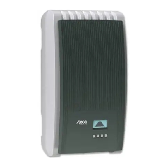
Structure and function Housing 3.1.1 coolcept ① Hood ② Display (monochrome, 128 x 64 pixels) ③ Rating plate, serial number, warnings ④ Operating buttons: ESC, r, s, SET (from left to right) ⑤ 1x AC connection ⑥ 1x DC connection Minus (−) for solar modules (Phoenix Contact SUNCLIX, safe-touch) ⑦... - Page 15 3.1.2 coolcept-x ① Hood ② Display (monochrome, 128 x 64 pixels) ③ Rating plate, serial number, warnings ④ Operating buttons: ESC, r, s, SET (from left to right) ⑤ 1x AC connection ⑥ Pressure equalization membrane ⑦ 1x RJ45 socket (RS485 bus) ⑧...
-
Page 16: Operating Buttons
Faults are indicated by a red flashing background illumination. An incident message is concurrently shown. Note The display reacts more slowly at extremely low temperatures. In particular, this can apply for coolcept-xdevices if they are used outdoors. 747,431 | Z09 | 2015-09-30... - Page 17 3.3.2 Information The information shown on the display is described below using illustrative examples. Status display The status display shows the following values: ① Measurement name ② Measurement with units ③ Date is displayed alternatingly with IP address ④ Symbol Non-confirmed event messages; more information on this is provided in Section Ä...
- Page 18 Graphical yield (day, month, year) Daily, monthly and annual yields can be displayed graphically in a chart. ① Period for a single yield value (here: day yield) ② y-axis: Yield in kWh With an extra M: yield in MWh The scaling changes depending on the maximum value. ③...
- Page 19 Information The menu item Information contains the following sub-menu items. Contact data System information (see Fig. left): – Product designation – Serial number of the inverter – Information concerning the software and hardware version of the inverter (see sample ① in Fig. left) –...
- Page 20 3.3.3 Settings Numerical settings ① Designation of the numerical setting ② Value to be set; the selected value to be set is highlighted in black. When performing numerical settings of remuneration and dates, the following applies: Remuneration Possible currencies: £ (Pounds), € (Euros), kr (Krones), none. The maximum value that can be set for remuneration is limited for technical reasons.
- Page 21 Possible causes: Internal temperature too high User default Power limiter Frequency too high Controlled by grid operator (feed-in management) Delayed increase in power after starting Can be reset to 0 via Settings ▶ Reset max. vals. Acoustic alarm An acoustic alarm sounds (approx. 4.5 kHz) when an event message is displayed.
- Page 22 Network settings, required for network communication, e. g. with an Internet portal: DHCP: Switch DHCP on/off IP address: IP address of the inverter Subnet mask: Subnet mask of the inverter Gateway: IP address of the network gateway DNS address: IP address of the DNS server Web portal: Settings at the web portal –...
- Page 23 Fixed voltage The device can regulate the input voltage to a manually adjustable value. This switches off the automatic setting of the MPP (MPP tracking). The input voltage can be adjusted over a range between the maximum and minimum input voltage and the minimum input voltage in 1V steps.
- Page 24 Frequency limits The following frequency limits can be changed: Upper disconnection value Lower disconnection value (Fig. left) Derating switch-on threshold (because frequency is too high) Frequency threshold when switching on again Voltage limits ø (average value) The following voltage limits can be changed: Upper disconnection value (Fig.
-
Page 25: Cooling
Technical details Each characteristic curve is defined by 2 to 8 nodes. A node is defined by the output power P of the inverter (x-axis) and the associated phase shift (y-axis). The phase shift can be set over a range of 0.95 (overexcitation) through 1.00 (no phase shift) to 0.95 (underexcitation). - Page 26 Internet portal as illustrated below. This service is free of charge for a period of 2 years from the time of registration. The following applies: Before the Internet portal can be used, the user must www.steca.com/portal register. More Ä , p. 9 information on this is provided in 5.4...
- Page 27 Note The network cable must be disconnected in order to prevent transmission of the data, or data transmission must be disabled according to Ä , p. 21 . Fig. 4: Graphical representation of the yield data in the Internet portal Furthermore, you can use the TCP/IP interface to display yield data and other information as HTML pages.
- Page 28 Fig. 7: Example 2 of an HTML page 3.6.3 RS485 bus The inverter communicates with other devices via an RS485 bus. The following applies: The inverter has two RS485 interfaces (RJ45 sockets) on the lower side of the casing. The inverter has two RS485 interfaces (RJ45 sockets) on the lower side of the casing. The beginning and end of the RS485 bus must be terminated;...
- Page 29 – Connection to the inverter via optional adapter RS485⇔USB is possible; the adapter is available from Steca under Article Number 746.610 (IP21) or 737.707 (IP65). – Load firmware updates (for technical professionals only) External data loggers, recommended by Steca for professional system monitoring: –...
- Page 30 Note The settings must be made on the external data loggers as specified by the manufacturer, before connecting. The cabling scheme of the RS485 bus is presented below. RS485 RS485 RS485 Fig. 9: Cabling scheme ① External data logger ② First inverter ③...
- Page 31 Pin assignment of the alternative RS485 data cable Device Inverter Solar-Log Kiwigrid WEB‘log Signal Connection RJ45 Terminal strip RJ12 Terminal strip ¤ Data A Data B — — — — — — — — Contact — — — — — —...
- Page 32 3.6.7 Modbus RTU The inverter communicates via Modbus RTU with energy meters. The following applies: Only energy meter pre-programmed in the inverter can be used. The energy meter must be installed in such a way that it records the power fed into the grid. 3.6.8 Modbus RTU data connection cable NOTICE!
-
Page 33: Installation
Installation Safety measures for the installation Observe the following safety notes when performing the work described in Section Installation. DANGER! Risk of death by electrocution! – Only technical professionals may perform the work described in Section Installation Carry out the measures described. –... - Page 34 NOTICE! Danger of damage to the inverter or derating! – The mounting location must satisfy the following conditions: – The mounting location and immediate environment are permanently fixed, vertical, flat, non-inflammable and not subject to constant vibration. – The permissible ambient conditions are conformed to; see Technical data Ä...
-
Page 35: Mount The Inverter
① at the top (example in Fig. left). ————————————————————————— Note With coolcept-x, you can secure the inverter with a padlock against theft or unauthorized removal. The padlock is inserted in a shackle which will lock into the retaining plate during mounting. Now, it is no longer possible to unlock the retaining plate. -
Page 36: Prepare Ac Connection
Fig. 11: Position of the sticker for covering the Protection Class II symbol Attaching the inverter on the mounting plate 1. Grasp inverter on the grip recesses ① (coolcept) or on the perimeter edge (coolcept-x), fit it onto the mounting plate ➊... - Page 37 4.3.2 Fault current circuit breaker If the local installation regulations require the installation of an external residual current circuit breaker, then a Type A residual current circuit breaker as per IEC 62109-1, § 7.3.8. is sufficient. 4.3.3 Assemble AC plug DANGER! Risk of death by electrocution! Observe the warning notes in Ä...
- Page 38 Wire the AC plug supplied to match the selected external conductors, as described in the Appendix under Mounting ⇒ AC plugs. Do not yet close the AC plug. Connect one of the two connected phases to PE at the inverter side. Make this connection inside the AC plug or use an external junction box, as shown in Fig.
-
Page 39: Prepare Dc Connections
Prepare DC connections DANGER! Risk of death by electrocution! – Observe the warning notes in Ä 4.1, p. 33 . – Use the provided SUNCLIX plugs so that the specified protection class is maintained. NOTICE! Danger of damage to the inverter and the modules. Connect the opposing connectors for the DC connections to the DC cable, observing the correct polarity. -
Page 40: Initial Commissioning Of The Inverter
200 mm, to avoid interference in the data transmission. – The protection class IP65 for type coolcept-x is only ensured if the AC and DC plugs are plugged in and the RJ45 sockets are sealed with sealing caps. - Page 41 If the Countries table does not list your country, select a country with stricter specifications. The country setting does not affect the language used on the display. The display language is set separately. 4.7.2 Operation Starting initial commissioning ✔ The check list for initial commissioning is displayed: The default display language is English.
- Page 42 Date 1. Press SET. The day flashes. 2. Press rs to change the day. 3. Press SET. The change is adopted. 4. Press s. The month is selected. 5. Repeat steps 1 to 3 for the month. 6. Press s. The year is selected. 7.
- Page 43 3. Press ESC; the dialogue shown at the left is displayed. 4. Press ESC to select a different country by performing step 1 and step 2, or Press SET for a longer period of time (> 1 s) to confirm the currently selected country.
- Page 44 Reactive power ——————————————————————————— NOTICE The following items are only displayed when the use of a reactive power characteristic curve is prescribed for the country currently selected in the Country item: The following items are only displayed when the use of a reactive power setting is prescribed for the country currently selected in the Country item: –...
- Page 45 Load samples ——————————————————————————— NOTE If cosPhi = 1 was not selected, an additional menu item "Load samples" is indicated. ——————————————————————————— Press s to select "Load samples". Press SET. Press rs to select a default characteristic line. Press SET. The default characteristic line is adopted. Press ESC.
- Page 46 Display characteristic curve 1. The previously set reactive power characteristic curve is displayed graphically (example in Fig. left). 2. Press ESC. The check list is shown. Finish ✔ Finish has been selected in the check list and SET has been pressed.
-
Page 47: Feed-In Management
Feed-in management Depending on the country, photovoltaic systems must have the possibility of being reduced in the fed-in effective power by the network operator. The following products are recommended for implementing this legally prescribed specification: StecaGrid SEM WEB'log from Meteocontrol Solar-Log from Solare Datensysteme Energy-Manager from Kiwigrid Furthermore, an energy meter can be used for feed-in management. -
Page 48: Switch Dc On
(approx. 2 minutes), the injected power can be shown on the display (the incidence of sunlight is a prerequisite). ——————————————————————————— Note On the coolcept-xdevices the DC load-break switch can be safeguarded against being switched on unintentionally with a padlock (shackle thickness max. 7 mm). ———————————————————————————... - Page 49 Switching off the AC and DC supplies 1. Turn the AC circuit breaker to off. 2. Set the DC circuit breaker on the inverter to position 0 (Fig. left). Disconnecting the DC connections from the inverter u Disconnect the DC cable plug connectors according to the manufacturer's instructions;...
-
Page 50: Operation
Operation Overview of operating functions Status Main menu Submenus display Output power Yield Daily Time/date Mode *) off *) Current day Remuneration Remuneration Dyn. feedin Energy Monthly yield *) control *) meter *) Self Energy Configuration PV voltage Annual Meter type *) consumption *) management *) Connection... -
Page 51: General Operating Functions
General operating functions Hidden content is shown using the r and s buttons. Repeated button presses: If rs need to be pressed repeatedly, you can alternatively hold these buttons pressed for a long time. The rate of repetition increases the longer the button is held. - Page 52 Displaying yields numerically (list) and graphically (chart) ✔ The status display is shown. 1. Press ‘SET’ . The main menu is displayed with ‘Yield’ selected. 2. Press ‘SET’ . The list with yield time periods is shown. 3. Press rs to select a yield time period. 4.
-
Page 53: Internet Portal
4. Press s. The next value is selected. 5. Repeat steps 1 to 4 for the remaining values. 6. Press ESC. The next higher menu level is displayed. Calling up the service menu and editing the values NOTICE! Risk of yield losses and contravention of regulations and standards. Inverter and grid parameters can be changed in the service menu. - Page 54 Calling up the Internet portal, entering the language and serial number Enter the following address into the Internet browser (or click the address if you are reading this document as a PDF on a computer monitor): www.steca.com/portal. Ensure that scripts and cookies for www.steca.com/portal are permitted in the browser.
- Page 55 Entering the user data Fig. 15: Data entry form for user data NOTICE! The email address can only be entered once and cannot be subsequently changed! The email address is also the user name; see also ① in Ä Fig. , p. 59. Enter your email address into the field ①...
- Page 56 Entering system data Fig. 16: Data entry form for the system data 747,431 | Z09 | 2015-09-30...
- Page 57 for your solar system into the field ① in Fig. 16 . Enter any desired name of the system into the field ②. Enter the installed power of the system into the field ③. Observe the note ④. Enter a description Use the Google Maps buttons ⑤...
- Page 58 In field ② in Fig. , 18 enter the activation code you received via email as shown in Fig. 17 . Confirm via the button ③. If the registration was successful then Fig. 19 appears and you will receive an additional ð...
- Page 59 5.4.2 Login – Displaying yield data – Changing settings Enter the following address in your Internet browser: www.solare-energiewende.de. Ensure that scripts and cookies for www.solare-energiewende.de are permitted in the browser. The home page of the Internet portal as shown in Fig. 21 is displayed. ð...
- Page 60 Fig. 22: Yield display ① System data display ② Performance data display ③ Environmentally related data display ④ Buttons for changing the display ⑤ Yield charts display ⑥ Buttons for setting the period shown in ⑤ ⑦ Button for changing the system data, as described in Ä...
-
Page 61: Self Test
Self test The self test is mandatory for operation of inverters in Italy. Function The prerequisites for performing the self test are as follows: The country Italy was selected during initial commissioning. The level of solar irradiation is high enough to ensure that the inverter can feed the grid. During the self test, the inverter checks its switch-off behaviour with regard to too high / too low grid voltage and frequency (7 test phases, duration of approx. - Page 62 Operation ✔ The country Italy is set in the inverter to be tested. 1. Check the country setting via ‘Information’ ▶ ‘System info’ in the main menu as required. 2. Select ‘Self test’ in the main menu. The dialog shown at the left is displayed.
-
Page 63: Fault Rectification
Fault rectification Faults are indicated by event messages as described below. The display flashes red. The list of event messages below contains information on troubleshooting and fault correction. Structure Event messages contain the following information: ① Symbol for the type of event message ②... - Page 64 Operation Confirming event messages ✔ An event message with the comment ‘NEW’ is displayed. Press ‘ESC’ /r/s. The event message is confirmed. Displaying event messages Select ‘Event log’ in the main menu. Press ‘SET’ . The event messages are displayed in chronological order (latest message first). Press rs to page through the event messages.
- Page 65 Incident message Description Type The fault current that flows from the plus or minus input via Fault current too the solar modules, exceeds the permissible value. Pursuant to high statutory regulations, the inverter switches off automatically as long as this fault is pending. u Notify your installer.
- Page 66 Incident message Description Type The grid voltage applied on the inverter exceeds the Grid voltage too permissible value. Pursuant to statutory regulations, the high inverter switches off automatically as long as this fault is pending. u Contact your installer if this error occurs frequently. After switch-off, the inverter cannot inject again because the Grid voltage too grid voltage exceeds the legally prescribed switch-on value.
- Page 67 Incident message Description Type "After a firmware update, the different software statuses in the Incompatible inverter do not match any more. software 1. Repeat the firmware update using a valid update file. 2. Contact your installer if this error occurs frequently. Outer conductor and neutral conductor are connected L and N are swapped out.
- Page 68 Incident message Description Type The inverter cannot identify an internal component, or it does The boost not match the other components. The inverter cannot inject converter has a into the grid. wrong HW version u Notify your installer. The boost converter is defective, the inverter is not injecting The boost into the grid or is injecting at reduced power.
-
Page 69: Maintenance And Disposal
Clean the device as needed, as described below. NOTICE! Danger of destroying components on devices of type coolcept: – Ensure that cleaning agents and cleaning materials do not get between the cooling fins on the front of the inverter (under the grey hood). -
Page 70: Technical Data
Technical data Inverter 9.1.1 StecaGrid 1500/1500x/2000/2000x StecaGrid 1500/x StecaGrid 2000/x DC input side (PV generator connection) Number of DC inputs Maximum start voltage 420 V Maximum input voltage 420 V Minimum input voltage for 75 V grid-feeding Startup input voltage 90 V Rated input voltage 195 V... - Page 71 StecaGrid 1500/x StecaGrid 2000/x Rated output voltage 230 V Maximum output current 12 A Rated output current 6.5 A 8.7 A Maximum active power 1,500 W 2,000 W (cos φ = 1) Maximum active power 1,500 W 2,000 W (cos φ = 0.95) Maximum apparent power 1,580 VA 2,100 VA...
- Page 72 Overvoltage protection version Varistors Reverse polarity protection Operating conditions Area of application coolcept: indoor rooms, with or without air conditioning coolcept-x: indoor rooms, with or without air conditioning, outdoors with or without protection Climate classification pursuant coolcept: 3K3 to IEC 60721-3-3...
- Page 73 ≤ 4 mm Opposing connector Opposing connector included in delivery Dimensions (X x Y x Z) coolcept: 340 x 608 x 222 mm coolcept-x: 399 x 657 x 227 mm Weight coolcept: 8.3 kg; coolcept-x: 11 kg Display...
- Page 74 9.1.2 StecaGrid 2500/2500x/3010/3010x StecaGrid 2500/x StecaGrid 3100/x DC input side (PV generator connection) Number of DC inputs Maximum start voltage 600 V Maximum input voltage 600 V Minimum input voltage for 125 V grid-feeding Startup input voltage 150 V Rated input voltage 320 V 380 V Minimum input voltage for...
- Page 75 StecaGrid 2500/x StecaGrid 3100/x Rated output current 11 A 13 A Maximum active power 2,500 W 3,000 W (cos φ = 1) Maximum active power 2,500 W 3,000 W (cos φ = 0.95) Maximum apparent power 2,630 VA 3,160 VA (cos φ...
- Page 76 Overvoltage protection version Varistors Reverse polarity protection Operating conditions Area of application coolcept: indoor rooms, with or without air conditioning coolcept-x: indoor rooms, with or without air conditioning, outdoors with or without protection Climate classification pursuant coolcept: 3K3 to IEC 60721-3-3...
- Page 77 ≤ 4 mm Opposing connector Opposing connector included in delivery Dimensions (X x Y x Z) coolcept: 340 x 608 x 222 mm coolcept-x: 399 x 657 x 227 mm Weight coolcept: 9.6 kg; coolcept-x: 12 kg Display...
- Page 78 9.1.3 StecaGrid 3600/3600x/4200/4200x StecaGrid 3600/x StecaGrid 4200/x DC input side (PV generator connection) Number of DC inputs Maximum start voltage 845 V Maximum input voltage 845 V Minimum input voltage for 350 V grid-feeding Startup input voltage 350 V Rated input voltage 455 V 540 V Minimum input voltage for...
- Page 79 StecaGrid 3600/x StecaGrid 4200/x Rated output current 16 A 18.3 A Maximum active power 3680 W (Belgium: 3330 W) 4200 W (Belgium: 3330 W) (cos φ = 1) Maximum active power 3500 W 3990 W (cos φ = 0.95) Maximum apparent power 3680 VA 4200 VA (cos φ...
- Page 80 Overvoltage protection version Varistors Reverse polarity protection Operating conditions Area of application coolcept: indoor rooms, with or without air conditioning coolcept-x: indoor rooms, with or without air conditioning, outdoors with or without protection Climate classification pursuant coolcept: 3K3 to IEC 60721-3-3...
- Page 81 , conductor cross-section ≤ 4 mm section Opposing connector Opposing connector included in delivery Dimensions (X x Y x Z) coolcept: 340 x 608 x 222 mm coolcept-x: 399 x 657 x 227 mm Weight coolcept: 9.1 kg; coolcept-x: 11.5 kg Display...
-
Page 82: Ac Cable And Line Circuit Breakers
Table of countries Due to legal requirements, the values in the table above may change at short notice. For a current overview, go to http://www.steca.com/Wechselrichter-Wohnsiedlung. You'll find the table for the respective product family under Downloads Þ Certificates. 747,431 | Z09 | 2015-09-30... - Page 83 Liability, commercial guarantee, legal guarantee For the warranty terms for your device, go to http://www.steca.com/pv-grid/warranties. 747,431 | Z09 | 2015-09-30...
- Page 84 Contact In the case of complaints or faults, please contact the local dealer from whom you purchased the product. They will help you with any issues you may have. Europe Steca Elektronik GmbH Mammostrasse 1 87700 Memmingen Germany Phone +49 (0) 700 783 224 743 +49 700 STECAGRID Monday to Friday from 08:00 a.m.
- Page 85 Table of contents Assembly..........................86 747,431 | Z09 | 2015-09-30...
- Page 86 Assembly Bore dimension drawing for coolcept devices 747,431 | Z09 | 2015-09-30...
- Page 87 Bore dimension drawing for coolcept-x devices 747,431 | Z09 | 2015-09-30...
- Page 88 AC connector Wieland Electric GmbH gesis gesis RST 20i2/20i3 Brennerstraße 10-14 Hotline: 96052 Bamberg Gebrauchsanleitung für Tel.: +49 (951) 9324-996 Tel. +49 (951) 9324-0 Steckverbinder 2-,3-polig Fax: +49 (951) 9326-996 Fax +49 (951) 9324-198 Email: BIT.TS@wieland-electric.com Internet: www.wieland-electric.com Stand/Updated: 10/2009 Instructions for use for Internet: www.gesis.com Email: info@wieland-electric.com...
- Page 89 Verschließen ACHTUNG / CAUTION Closing Die Steckverbinder sind nicht zur Stromunterbrechung geeignet. Trennen oder stecken Sie die Verbindung niemals unter Last! Verschraubung: The connectors are not for current interrupting. Never connect or Anzugsmoment disconnect under load! typ. 4+1 Nm Screw connection: Leiterdemontage Tightening torque Unlocking...
- Page 90 Gehäuseeinbau mit M25-Durchführung HINWEISE / NOTES Housing installation with M25 feedthrough Die Installationssteckverbinder RST 20i2…- i3… sind nach RL 94/9/EG (ATEX 95) An-hang I Geräte der Gerätegruppe II Kategorie 3G die nach RL 99/92/EG (ATEX 137) in der Zone 2 sowie den Gasgruppen IIA, IIB und IIC, die durch brenn- bare Stoffe im Bereich der Temperaturklassen T1 bis T6 explosionsgefährdet sind, 11,7 0,2 mm eingesetzt werden dürfen.
- Page 91 Phoenix Contact SUNCLIX (DC connector) 747,431 | Z09 | 2015-09-30...
- Page 92 747,431 | Z09 | 2015-09-30...
- Page 93 747.431 | Z09 | 2015-09-30...
Need help?
Do you have a question about the coolcept and is the answer not in the manual?
Questions and answers