
Subscribe to Our Youtube Channel
Related Manuals for Steca Solarix 2020-x2


Summary of Contents for Steca Solarix 2020-x2
- Page 1 Solar charge controller Solar charge controller for two batteries 12 V/24 V 20 A Installation and operating instructions 751.792 | Z01 | 1504...
-
Page 2: Table Of Contents
About these operating instructions Contents About these operating instructions ........... 2 Safety ..................3 Description ................4 Installation ................7 Maintenance ................12 Self test ................... 12 Faults and remedies ..............13 Technical data ................. 18 Commercial and legal guarantee conditions ......22 About these operating instructions These operating instructions are part of the product. -
Page 3: Safety
Safety Safety 2.1 Designated use The solar charge controller may only be used for charging and controlling lead-acid batteries (with liquid or solid electrolyte). The solar charge controller may only be connected to a solar generator (solar module or array of solar modules within the limits of the permissible connection values) and must not be connected to any other energy source. -
Page 4: Description
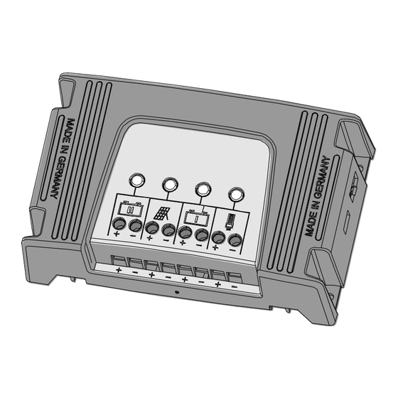
Description Danger of fire and explosion Do not use the solar charge controller in any of the following situations: In dusty environments In the vicinity of solvents In environments where inflammable gases and Do not expose the batteries to open flames or sparks. vapours can be present ... - Page 5 Description USB charge socket (e.g. for charging a mobile phone) Can be expanded with an external remote display Can be integrated into the StecaLink bus system Structure: LED 1 and terminal block for auxiliary battery (battery II) LED 2 and terminal block for solar module LED 3 and terminal block for main battery (battery I) LED 4 and terminal block for connecting loads (load circuit)
- Page 6 Description When only one battery is used then this must be connected to the main battery terminals. The charging times depend on the power provided by the solar module and the capacity of the battery. With a maximum load current of 20 A the load circuit is suitable for external appliances with a power rating of up to 240 W at 12 V and 480 W at 24 V.
-
Page 7: Installation
Installation LED 2 Meaning Solar module Green fully lit Solar module connected, no charging current flowing Green slowly alternating Charging current flowing between bright/dark Yellow fully lit Solar module voltage too low Solar module voltage below 8 V LED 4 Meaning Load circuit Green fully lit... - Page 8 Installation Mount the solar charge controller upright on a non- inflammable surface. Maintain a minimum clearance of 10 cm above and below the unit to ensure free circulation of air. Mount the solar charge controller as close as possible to the batteries (but with a safety clearance of at least 30 cm).
- Page 9 Installation 2.5-10 mm² max. 10 m 2.5-10 mm² max. 2 m 2.5-10 mm² 240 W (12 V) max. 2 m 2.5-10 mm² 480 W (24 V) Fuse Fuse max. 10 m Load output 30/40 A 30/40 A =60 V =20 V Cable cross sections Distance 10 m...
- Page 10 Installation Connecting the batteries (first battery I, then battery II) The main battery is connected to “Battery I”, the auxiliary battery is connected to “Battery II”. 1. Label the battery connection cables as a plus cable (B1+ or B2+) and a minus cable (B1- or B2-). 2.
- Page 11 Installation 5. Connect the minus cable M- with the correct polarity to the solar module terminal pair on the solar charge controller. 6. Remove the covering from the solar module. When the solar module is correctly connected, LED 2 lights up green (permanently or alternating between bright/dark).
-
Page 12: Maintenance
Maintenance Maintenance Clean the solar charge controller as necessary using a brush or soft cloth. Do not use water for cleaning. Ensure adequate ventilation at the rear side of the housing (heatsinks). Check the cable strain relief. ... -
Page 13: Faults And Remedies
Faults and remedies Display Meaning LED 2 flashes red Defective USB charge socket LED 3 flashes red Fault in main battery charge control LED 4 flashes red Defective load switch Faults and remedies After a shutdown the supply to the loads in the load circuit and the battery charging are resumed as soon as the conditions causing the shutdown are again within a permissible range. - Page 14 Faults and remedies Cause Remedy Error/ Fault message No display Hibernation - Check solar module mode active voltage - Wait 30 minutes Charge the battery Battery voltage too low The external fuse Replace the external fuse in the battery connection cable has blown Battery (Battery I) - Disconnect all connec-...
- Page 15 Faults and remedies Cause Remedy Error/ Fault message Load circuit LED 4 lights up Short circuit in - Disconnect loads load circuit - Correct the cause of the short circuit - Reconnect loads LED 4 flashes Overload warning Reduce current con- red (slowly) sumption of the loads, if necessary switch off or...
- Page 16 Faults and remedies Cause Remedy Error/ Fault message Battery LED 1 and/or Battery is con- Connect the battery with the correct polarity LED 3 lights up nected with the blue wrong polarity LED 1 and/or Battery overvolt- - Disconnect the battery LED 3 flashes - Correct the cause of red/green...
- Page 17 Faults and remedies Cause Remedy Error/ Fault message Solar module LED 2 lights up Solar module Connect the solar mod- blue connected with ule with the correct incorrect polarity polarity LED 2 lights up Short circuit at Correct the cause of the short circuit solar module input...
-
Page 18: Technical Data
Technical data Technical data General information Dimensions 190 mm x 120 mm x 58 mm Weight 500 g Current consumption Approx. 20 mA Reference potential Minus Earthing The negative pole can be earthed but this is not essen- tial. Never earth the plus pole! Maximum heatsink tempera- 70 °C ture (rear side of unit) - Page 19 Technical data Battery charging Type Lead-acid batteries with gel (default setting) or liquid elec- trolyte Voltage 12 V DC / 24 V DC Battery I Battery II Mixed connection of 12 V 12 V 12 V and 24 V batteries is only 24 V 24 V permitted according to the...
- Page 20 Technical data Detailed battery charging 12 V system 24 V system data Permissible battery voltage 9-17 V 17.1-34 V range Deep discharge pre-warning at 12.0 V 24 V Deep discharge protection at 11.7 V 23.4 V Switch-on voltage 12.5 V 25 V Cut-off voltage for float 14.1 V...
- Page 21 Technical data Electronic protection functions Overcharge/deep discharge protection for the batteries Reverse polarity protection for the solar module , load circuit and batteries Battery overvoltage shutdown Automatic electronic fuse Overtemperature and overload protection Short-circuit protection for load circuit and solar module ...
-
Page 22: Commercial And Legal Guarantee Conditions
Commercial and legal guarantee conditions Commercial and legal guarantee conditions In accordance with German statutory regulations, there is a 2-year legal guarantee on this product for the customer. The manufacturer provides a voluntary 5-year commercial guarantee to the specialist dealer from the date of invoice or receipt.
Need help?
Do you have a question about the Solarix 2020-x2 and is the answer not in the manual?
Questions and answers