
Related Manuals for Steca coolcept3


Summary of Contents for Steca coolcept3
- Page 1 coolcept coolcept Installation and operating instructions Notice d'installation et d'utilisation 750.661 | Z03 | 2016-09-12...
-
Page 2: Table Of Contents
Table of contents Preface................. 4 General information............5 General safety instructions........... 5 Identification..............6 Scope of delivery............7 Intended use..............7 About this manual............8 Structure and function............. 11 Housing..............11 Operating buttons............. 13 Display............... 13 Cooling..............20 Grid monitoring............20 Data communication.......... - Page 3 Contact................71 Appendix................72 Assembly..............73 Bore dimension drawing for coolcept devices..73 Bore dimension drawing for coolcept -x devices..74 AC plug..............75 Phoenix Contact SUNCLIX (DC connector)....77 750.661 | Z03 | 2016-09-12...
-
Page 4: Preface
Preface Thank you for choosing inverters from the coolcept range of prod- ucts manufactured by Steca Elektronik GmbH. By using solar energy you make a significant contribution to environmental protection by reducing the total amount of atmospheric pollution caused by carbon dioxide (CO ) and other damaging gases. -
Page 5: General Information
General information General safety instructions This document is part of the product. Install and use the device only after reading and understanding this document. Always perform the measures described in this document in the sequence specified. Keep this document in a safe place for the entire service life of the device. -
Page 6: Identification
Safety instructions on the device ① Serial number as a bar code and in plain text ② Warning of hot surface, only coolcept³-x ③ Dangerous voltages can remain present on the components up to 10 minutes after switching off the DC circuit breaker and the line circuit breaker ④... -
Page 7: Scope Of Delivery
Rating plate ① Bar code for internal use ② Technical data of DC-Bat connection (for coolcept devices only) and protection class ③ Technical data - DC-PV input ④ Article number and product designation ⑤ Manufacturer and address ⑥ Cover the Protection class II and CE mark ⑦... -
Page 8: About This Manual
If the maximum AC operating voltage is higher than the max- imum system voltage of the photovoltaic generator, then PV generators must be used that have a maximum system voltage that is higher than the AC grid voltage. The battery connection contacts are intended for an optional energy storage system. -
Page 9: Z03 | 2016
2.5.3 Designations Symbols The following table contains the symbols used in this manual Warning signs Type of danger Warning – high-voltage. Warning – danger zone. Symbols used on the Tab. 1: The following table contains the symbols used on the device. device Cover the Description... - Page 10 Abbreviations Abbreviation Description Derating Power reduction DHCP DHCP automatically integrates the device in an existing network (acronym: Dynamic Host Configuration Protocol) Internal grid monitoring of the inverter (English: Mains monitoring with allocated Switching Devices). Working point producing the most power (English: maximum power point) MPP tracker Controls the power of the connected module strings to match the MPP...
-
Page 11: Structure And Function
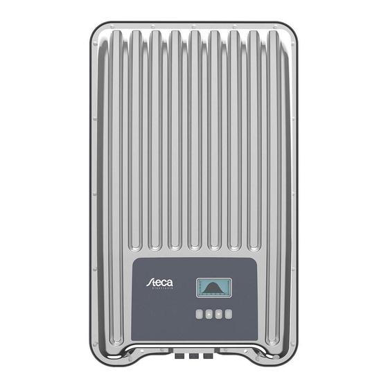
Structure and function Housing 3.1.1 coolcept ① Hood ② Display (monochrome, 128 x 64 pixels) ③ Rating plate, serial number, warnings ④ Operating buttons: ESC, r, s, SET (from left to right) ⑤ 1x AC connection ⑥ 1x DC connection Minus (−) for optional energy storage system (Phoenix Contact SUNCLIX, safe to touch) ⑦... -
Page 12: Z03 | 2016
3.1.2 coolcept ① Hood ② Display (monochrome, 128 x 64 pixels) ③ Rating plate, serial number, warnings ④ Operating buttons: ESC, r, s, SET (from left to right) ⑤ 1x AC connection ⑥ Pressure equalization membrane ⑦ 1x RJ45 socket (RS485 bus) ⑧... -
Page 13: Operating Buttons
Operating buttons The operating buttons ④ in Ä Chapter 3.1.1 „coolcept “ on page 11 and in Ä Chapter 3.1.2 „coolcept -x“ on page 12 have the following functions: Function Button Action General guided operation Press briefly Goes to the next higher menu Navigates 1 step back level Discards any changes... - Page 14 3.3.2 Information The information shown on the display is described below using illus- trative examples. Status display The status display shows the following values: ① Measurement name ② Measurement with units ③ Date is displayed alternatingly with IP address ④ Cover the Non-confirmed event messages;...
- Page 15 Event messages Ä Chapter 6 „Fault rectification“ on page 50 PV generator character- istic curve ① X axis: input voltage in V ② Y axis: power in kW ③ Peak = MPP If the „Ch. Curve“ menu item is called, the inverter records the PV generator characteristic curve and then displays it (Fig.
- Page 16 Network: Network parameters, partially configurable under Settings ▶ Network – Host name: Unique name in the network – DHCP status: DHCP on/off – Link status: Status of the network connection – IP address: IP address of the inverter – Subnet mask: Subnet mask of the inverter –...
- Page 17 Max. daily yield: The maximum daily yield achieved Operating hours: The operating hours during which the device has been connected to the grid (including night-time hours). Total yield: Yield since commissioning savings: CO savings achieved since commissioning Measurement is always displayed (cannot be switched off) Possible causes: –...
-
Page 18: Service Menu
DNS address: IP address of the DNS server web-portal: Settings at the web portal – Web portal setting: Disabling of data transmission and selection of a web portal – Re-transmission: Data in the inverter is transmitted a second time – Connection check: Checks the internet connection and indicates the result 3.3.4... - Page 19 Delete country setting After the country setting has been deleted the device restarts anew and displays the guided 1st commissioning menu. Factory setting Resetting the device to the factory setting deletes the following data: Yield data Event messages Date and time Country setting Display language Network settings...
-
Page 20: Cooling
All parameters Service technicians can use this menu item for changing additional MSD parameters. Cooling The internal temperature control system prevents excessive oper- ating temperatures. When the internal temperature is too high, the inverter adjusts the power consumption from the PV generators to reduce the heat dissipation and operating temperature. - Page 21 2 years from the time of registration. The following applies: Before the Internet portal can be used, the user must go to www.steca.com/portal to register. The local network settings must be set at the inverter in order to establish a connection to the Internet portal server. This can be...
- Page 22 Fig. 1: Graphical representation of the yield data in the Internet portal Furthermore, you can use the TCP/IP interface to display yield data and other information as HTML pages. You need a PC connection to indicate the data. The HTML pages can be displays by means of a browser, such as Mozilla Firefox.
- Page 23 Fig. 4: Example 2 of an HTML page To display the HTML pages, the chart.js licence- free software is used, www.chartjs.org. Copy- right (c) 2013-2015 Nick Downie." The HTML pages are the simplest way to update the firmware of the inverter.
- Page 24 Notice The following inverters have compatible data interfaces and can be connected to the RS485 bus as slaves: – StecaGrid 2020 – StecaGrid 1500, 1800, 2000, 2300, 2500, 3000, 3010, 3600, 4200 and StecaGrid 1500x, 1800x, 2000x, 2300x, 2500x, 3010x, 3600x, 4200x –...
- Page 25 Notice If in the country setting Italy is set, then the RS485 bus must be connected as follows to enable control through an external device in accordance with CEI 0-21. – External fast switch-off (ital.: Teledistacco): If the lines 3 and 8 of the RS485 bus connected, e.
- Page 26 This is available on our homepage see http:// www.steca.com/index.php?StecaGrid_User_de – Connection to the inverter via optional adapter RS485⇔USB is possible; the adapter is available from Steca under Article Number 746.610 (IP21) or 737.707 (IP65). – Load firmware updates (for technical professionals only)
- Page 27 The alternative data connection cable is a Cat-5 cable for long data connections. The following applies to the alternative data connec- tion cable: The total length of the RS485 bus must not exceed 1,000 m (Master/first inverter to last inverter). Use the pin assignment according to the table below if the alternative data connection cable is connected to the RJ45 socket of the first inverter or to the connector of an external...
- Page 28 The address is changed at the inverter via the menu items „Settings“ ▶ „Address“ . Only addresses ranging from 1 – 99 may be set. The bus master devices usually support less than 99 addresses. Consult the respective operating instructions for these devices before setting the addresses of the inverters.
- Page 29 NOTICE! Danger of destroying the Modbus RTU input of the inverter. Contact 4 of the RJ10 socket of the inverter carries voltage <20V. Do not use this contact. 750.661 | Z03 | 2016-09-12...
-
Page 30: Installation
Installation Safety measures during installation Observe the following safety notes when performing the work described in Section Installation . DANGER! Risk of death by electrocution! – Only technical professionals may perform the work described in Section Installation . – Do not connect cables to the inverter until explicitly asked to do so in the manual. - Page 31 Check that all pins of the AC plug are free of voltage. Use a suitable voltmeter for this (do not use a simple neon phase checker). NOTICE! Risk of damage to the inverter or derating! – The mounting location must satisfy the fol- lowing conditions: –...
-
Page 32: Mounting The Inverter
Mounting the inverter Fastening the mounting plate u Screw the mounting plate to the mounting surface using 4 screws: Use screws (and dowels etc.) appropriate for the weight of the inverter. The mounting plate must lie flat on the mounting surface and the metal strips at the sides must point forwards (Fig. -
Page 33: Prepare Ac Connection
Attaching the inverter on the mounting plate NOTICE! How to remove the inverter from the mounting plate is described under Ä Chapter 4.9 „Switch on DC“ on page 44. Grasp inverter on the grip recesses ① (coolcept ) or by the perimeter edge (coolcept -x), fit it onto the mounting plate ➊so that it is centred ②... -
Page 34: Prepare Dc Connections
Only an energy storage system approved by Steca may be connected to the battery connec- tions. If this instruction is not complied with, there is danger of damaging the inverter and the mod- ules. -
Page 35: Initial Commissioning Of The Inverter
NOTICE! – Between the data connection cables (RS485/ Ethernet/Modbus RTU) and the DC/AC lines, maintain a distance of 200 mm, to avoid interference in the data transmission. – The protection class IP65 for type coolcept x is only ensured if the AC and DC plugs are plugged in and the RJ45 sockets are sealed with sealing caps. - Page 36 Countries table on the Steca home- page, www.steca.com/Wechselrichter-Wohnsiedlung. The country can only be set once! Contact the Steca Technical Support if you have set the wrong country. If the Countries table does not list your country, select a country with stricter specifications.
- Page 37 Date format Press rs to select a date format. Press SET. The date format is adopted. ð Press ESC. ✓ The check list is shown. Date Press SET. The day flashes. ð Press rs to change the day. Press SET. The change is adopted.
- Page 38 Time Press SET. The hours display flashes. ð Press rs to change the hour. Press SET. The change is adopted. ð Press s. The minutes are selected. ð Repeat steps 1 to 3 for the minutes. Press ESC. ✓ The check list is shown. Country selection NOTICE! The country can only be set once!
- Page 39 Reactive power NOTICE! The following items are only displayed when the use of a reactive power characteristic curve is prescribed for the country currently selected in the Country item: – Mode: Type of characteristic curve Select one of the following types: - cos phi = 1 - Q(P) - Q(U) linear...
- Page 40 Loading defaults NOTICE! If cosPhi = 1 was not selected, an additional menu item Load defaults is indicated. Press s to select "Load defaults". Press SET. Press rs to select a default characteristic line. Press SET. The default characteristic line is adopted. ð...
- Page 41 Node n NOTICE! P % cannot be changed at the first and last nodes (000 %, 100 %). Press rs to select a parameter for the node. Press SET. The parameter value flashes. ð Press rs to change the value. Press SET.
- Page 42 Press and hold SET (> 1 s) to finish 1st commissioning. ✓ If SET was pressed for a longer time then the inverter starts anew and synchronises itself with the grid (Fig. left). 750.661 | Z03 | 2016-09-12...
-
Page 43: Feed-In Management
Feed-in management Depending on the country, photovoltaic systems must have the pos- sibility of being reduced in the fed-in effective power by the network operator. The following products are recommended for imple- menting this legally prescribed specification: StecaGrid SEM WEB'log from Meteocontrol Solar-Log from Solare Datensysteme Energy-Manager from Kiwigrid Furthermore, an energy meter can be used for feed-in management. -
Page 44: Switch On Dc
Press SET to call up the item. Press rs to select a meter type. Press SET. Press ESC to quit the sub-menu. Switch on DC Place DC load-break switch on the inverter on position I (Fig. left). After testing via the internal MSD (approx. 2 minutes), the power fed into the grid can be shown on the display (assuming that sunlight is present). - Page 45 Disconnecting the DC connections from the inverter Disconnect the DC cable plug connectors according to the manufacturer's instructions; see appendix. WARNING! DC cables carry voltage when the PV generators are subjected to sunlight. Disconnecting the AC plug from the inverter Disconnecting the AC plug from the inverter Release the safety clip at the front of the AC plug by depressing it with a suitable object, then pull the plug out.
-
Page 46: Operation
Operation Overview of operating functions Status Main menu Submenus display Daily Mode *) off *) Output power Yield Time/date Current day Remuneration Remuneration Dyn. feedin Monthly SolUse *) yield *) control *) Self Energy Configuration Energy PV voltage Annual consumption *) management *) meter *) PV current... -
Page 47: General Operating Functions
General operating functions Hidden content is shown using the r and s buttons. Repeated button presses: If rs need to be pressed repeatedly, you can alternatively hold these buttons pressed for a long time. The rate of repetition increases the longer the button is held. - Page 48 Press SET. The selected individual yield is shown in a chart (Fig. ð left). Press rs to page through the charts. Press SET to return to the list. Editing selection lists containing check boxes A selection list with check boxes is displayed (Fig. left). Press rs to select a check box.
-
Page 49: Internet Portal
(e.g. Voltage limits). The menu items are described in Ä Chapter 3.3.4 „Ser- vice menu“ on page 18. Internet portal For a StecaGrid portal description and the registration page of your system, go to www.steca.com/portal. 750.661 | Z03 | 2016-09-12... -
Page 50: Fault Rectification
Fault rectification Faults are indicated by event messages as described below. The dis- play flashes red. The list of event messages below contains informa- tion on troubleshooting and fault correction. Structure Event messages contain the following information: ① Symbol for the type of event message ②... - Page 51 Displaying event mes- Select Event log in the main menu. sages Press SET. The event messages are displayed in chronological order ð (latest message first). Press rs to page through the event messages. Event messages Event message Description Type There is an inconsistency between the selected country setting CountryCode and the country setting stored in memory.
- Page 52 Event message Description Type The grid frequency applied on the inverter is below the permis- Grid frequency sible value. Pursuant to statutory regulations, the inverter too low switches off automatically as long as this fault is pending. u Contact your installer if this error occurs frequently. After switch-off, the inverter cannot inject again because the Grid frequency grid voltage is below the legally prescribed switch-on value.
- Page 53 Event message Description Type u Contact your installer if this alarm occurs frequently. Intern. info u Contact your installer if this alarm occurs frequently. Intern. warning The insulating resistor between plus and minus input and Isolation error ground underranges the permissible value. For safety reasons the inverter is not allowed to inject into the grid.
- Page 54 Event message Description Type The fault current that flows from the plus or minus input via Residual current the PV generators exceeds the permissible value. Pursuant to too high statutory regulations, the inverter switches off automatically as long as this fault is pending. u Notify your installer.
-
Page 55: Maintenance And Disposal
Maintenance and disposal Maintenance The inverter is virtually maintenance-free. Nevertheless, we recom- mend that you inspect it regularly to ensure that the fins on the front and rear of the device are free of dust. Clean the device when necessary as described below. NOTICE! Danger of destroying components on devices of type coolcept... -
Page 56: Disposal
Disposal The crossed-out wheelie bin symbol on the device indicates that this product must not be disposed of with the normal household waste. It must be taken to a collection point for waste electrical and elec- tronic equipment. Information on the collection points can be obtained from the local waste disposal company, the next collection point for household waste or from the dealer where you bought your device. -
Page 57: Technical Data
Technical data Inverter 8.1.1 StecaGrid 3203/3203x/4003/4003x StecaGrid 3203/x StecaGrid 4003/x DC input side (PV generator connection) Number of DC inputs Maximum start voltage 1000 V Maximum input voltage 1000 V Minimum input voltage for 250 V feeding-in Start input voltage 250 V Rated input voltage 415 V... - Page 58 StecaGrid 3203/x StecaGrid 4003/x AC output side (grid connection) Output voltage 320 V to 480 V (depending on the country settings) Rated output voltage 400 V Maximum output current Maximum inrush current 16 A (for 10 ms) (switch-on current) RMS short-circuit current 3.82 A (for 60 ms) Rated output current...
- Page 59 StecaGrid 3203/x StecaGrid 4003/x Efficiency values (at 5 %, 10 %, 82 %, 91.7 %, 95.6 %, 96.2 %, 87.3 %, 93.7 %, 96.5 %, 20 %, 25 %, 30 %, 50 %, 75 %, 96.8 %, 97.5 %, 97.7 %, 97.1 %, 97.4 %, 97.9 %, 100 % of the rated power) at 97.1 %...
- Page 60 StecaGrid 3203/x StecaGrid 4003/x Storage temperature –30 °C ... +70 °C Relative humidity coolcept : 0 % ... 95 %, non-condensing coolcept -x: 0 % ... 100 % Installation altitude ≤ 2000 m above sea level Degree of pollution Noise emission (typical) 29 dBA Impermissible ambient gases Ammonia, solvents...
- Page 61 Certificates download see the product page on our homepage. Technical data at 25 °C / 77 °F Only Steca storage-ready devices may be connected to the storage system connection. Batteries cannot be connected directly. Due to its design the inverter cannot cause any DC fault currents.
- Page 62 StecaGrid 4803x StecaGrid 5503x Derating / power limiting occurs automatically when: input power > max. recommended PV power Cooling is inadequate Input current too high Output current too high Grid frequency too high (in accordance with country setting) Limiting signal on external interface Output power limited (set on the inverter) DC side (storage connection) Voltage...
- Page 63 StecaGrid 4803x StecaGrid 5503x Feeding phases Three-phase Distortion factor (cos φ = 1) < 1 % Power factor cos φ 0.8 capacitive ... 0.8 inductive Characterization of the operating behaviour Maximum efficiency 98.7 % European efficiency 98.2 % 98.3 % California efficiency 98.5 % 98.5 %...
- Page 64 StecaGrid 4803x StecaGrid 5503x Version overvoltage protection Varistors Reverse polarity protection Implementation conditions Implementation area indoor rooms, with or without air conditioning, out of doors with or without protection Climate classification pursuant to 4K4H IEC 60721-3-3 Ambient temperature –15 °C ... +60 °C Storage temperature –30 °C ...
- Page 65 Certificates download see the product page on our home- page. Technical data at 25 °C / 77 °F Only Steca storage-ready devices may be connected to the storage system connection. Batteries cannot be connected directly. Due to its design the inverter cannot cause any DC fault currents.
- Page 66 StecaGrid 5003 StecaGrid 6003 Derating / power limiting occurs automatically when: input power > max. recommended PV power Cooling is inadequate Input current too high Output current too high Grid frequency too high (in accordance with country setting) Limiting signal on external interface Output power limited (set on the inverter) DC side (storage connection) Voltage...
- Page 67 StecaGrid 5003 StecaGrid 6003 Feeding phases Three-phase Distortion factor (cos φ = 1) < 1 % Power factor cos φ 0.8 capacitive ... 0.8 inductive Characterization of the operating behaviour Maximum efficiency 98.7 % European efficiency 98.2 % 98.3 % California efficiency 98.5 % 98.5 %...
- Page 68 StecaGrid 5003 StecaGrid 6003 Version overvoltage protection Varistors Reverse polarity protection Implementation conditions Implementation area Indoor rooms, with or without air conditioning Climate classification pursuant to IEC 60721-3-3 Ambient temperature –15 °C ... +60 °C Storage temperature –30 °C ... +70 °C Relative humidity 0 % ...
-
Page 69: Ac Cables And Line Circuit Breakers
Certificates download see the product page on our home- page. Technical data at 25 °C / 77 °F Only Steca storage-ready devices may be connected to the storage system connection. Batteries cannot be connected directly. Due to its design the inverter cannot cause any DC fault currents. -
Page 70: Liability, Commercial Guarantee, Legal Guarantee
Liability, commercial guarantee, legal guarantee For the warranty terms for your device, go to http://www.steca.com/pv-grid/warranties. 750.661 | Z03 | 2016-09-12... -
Page 71: Contact
Contact In the case of complaints or faults, please contact the local dealer from whom you purchased the product. They will help you with any issues you may have. Europe Steca Elektronik GmbH Mammostrasse 1 87700 Memmingen Germany Phone +49 (0) 700 783 224 743 +49 700 STECAGRID Monday to Friday from 08:00 a.m. -
Page 72: Appendix
Appendix 750.661 | Z03 | 2016-09-12... -
Page 73: A Assembly
Assembly Bore dimension drawing for coolcept devices 750.661 | Z03 | 2016-09-12... -
Page 74: Bore Dimension Drawing For Coolcept -X Devices
Bore dimension drawing for coolcept -x devices 750.661 | Z03 | 2016-09-12... -
Page 75: Ac Plug
AC plug Wieland Electric GmbH gesis gesis RST 20i4/20i5/25i5 Brennerstraße 10-14 Hotline: 96052 Bamberg Montageanleitung für Tel.: +49 (951) 9324-996 Tel. +49 (951) 9324-0 Steckverbinder 4-,5-polig Fax: +49 (951) 9326-996 Fax +49 (951) 9324-198 Email: BIT.TS@wieland-electric.com Internet: www.wieland-electric.com Montageanleitung (Mai 2006) Mounting Instructions for Internet: www.gesis.com Email: info@wieland-electric.com... - Page 76 Gehäuseeinbau mit M20-Durchführung Entriegeln und Trennen Housing installation with M20 feedthrough Housing installation with M20 feedthrough Unlocking and separating Unlocking and separating 8,7 + 0,2 mm Mutter: Anzugsmoment typ. 3…3,5 Nm Detail Nut: ∅ 21,75 ± 1,25 mm Tightening torque typ.
-
Page 77: Phoenix Contact Sunclix (Dc Connector)
Phoenix Contact SUNCLIX (DC connector) 750.661 | Z03 | 2016-09-12... - Page 78 750.661 | Z03 | 2016-09-12...
- Page 79 750.661 | Z02 | 2014-04-02...
- Page 80 750661...
Need help?
Do you have a question about the coolcept3 and is the answer not in the manual?
Questions and answers