
Related Manuals for Steca coolcept


Summary of Contents for Steca coolcept
- Page 1 Installations- und Bedienungsanleitung Installation and operating instructions Notice d'installation et d'utilisation DE EN 747.431 | Z08 | 2014-01-31...
-
Page 2: Table Of Contents
Bedienung........................44 Selbsttest........................55 Störungsbeseitigung...................... 58 Wartung und Entsorgung....................62 Technische Daten......................63 Haftung, Gewährleistung, Garantie................73 Kontakt......................... 75 coolcept – coolcept-x Grid inverter..................Preface........................... 79 General information....................... 80 Structure and function....................86 Installation........................102 Operation........................115 Self test........................126 Troubleshooting...................... - Page 3 Table of contents Preface..........................79 General information......................80 General safety instructions..................80 Identification....................... 81 Scope of delivery......................82 Proper usage....................... 82 About this manual....................... 83 Structure and function......................86 Casing......................... 86 Operating buttons....................... 88 Display......................... 88 Cooling........................96 Grid monitoring......................96 Data communication....................
- Page 4 Liability, commercial guarantee, legal guarantee............... 143 10.1 Exclusion of liability....................143 10.2 Commercial and legal guarantee conditions............143 Contact..........................145 747.431 | Z08 | 2014-01-31...
-
Page 5: Preface
The innovative inverter topology is based on a single-stage transformerless circuit concept and is integrated into all devices in the coolcept series. This unique technology allows peak efficiencies of 98.0 % or 98.6% to be achieved. Depending on the type, the European efficiency of the devices is also significantly greater than 98 % and sets new standards in photovoltaic grid-feed systems. -
Page 6: General Information
General information General safety instructions This document is part of the product. Install and use the device only after reading and understanding this document. Always perform the measures described in this document in the sequence specified. Keep this document in a safe place for the entire service life of the device. Pass the document on to subsequent owners and operators of the device. -
Page 7: Identification
Identification Feature Description coolcept (plastic casing): StecaGrid 1800, StecaGrid 2300, Types StecaGrid 3000, StecaGrid 3010, StecaGrid 3600, StecaGrid 4200 coolcept-x (stainless steel casing): StecaGrid 1800x, StecaGrid 2300x, StecaGrid 3010x, StecaGrid 3600x, StecaGrid 4200x Issue version of the manual Manufacturer's address Ä... -
Page 8: Scope Of Delivery
⇒ PV GRID CONNECTED ⇒ Grid inverters cates for the products are available on Scope of delivery Inverter ①, coolcept type (plastic casing) or coolcept-x type (stainless steel casing, IP65) Mounting plate ② for coolcept or coolcept-x AC plug ③... -
Page 9: About This Manual
About this manual 2.5.1 Contents These instructions describe the type coolcept and coolcept-x inverters. The differences between the types are marked in the text. These instructions contain all information required by a technical professional for setting up and operating the inverters. Follow the instructions of the respective manufacturers when installing other components (e.g. - Page 10 Persons who have the knowledge of terminology and the skills necessary for setting up and operating photovoltaic systems. Persons who have the necessary training, knowledge and experience, and knowledge of the applicable regulations in order to evaluate and recognise the dangers inherent in the following work: –...
- Page 11 Abbreviations Abbreviation Description Derating Derating DHCP The use of DHCP allows automatic integration of the device into an existing network (Dynamic Host Configuration Protocol) Internal grid monitoring of the inverter (Mains monitoring with allocated Switching Devices). Working point producing the most power (Maximum Power Point) MPP tracker Controls the power of the connected module strings to match the MPP SELV, TBTS, MBTS...
-
Page 12: Structure And Function
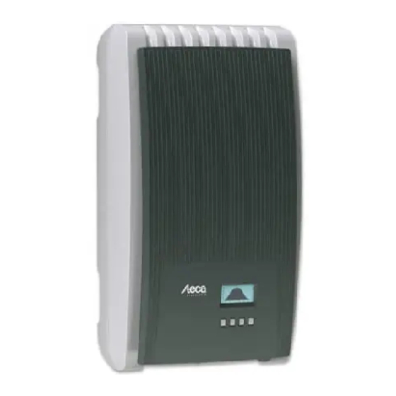
Structure and function Casing 3.1.1 coolcept ① Hood ② Display (monochrome, 128 x 64 pixels) ③ Type plate, warning notices ④ Operating buttons: ESC, r, s, SET (from left to right) ⑤ 1x AC connection ⑥ 2x RJ45 sockets (RS485 bus) ⑦... - Page 13 3.1.2 coolcept-x ① Hood ② Display (monochrome, 128 x 64 pixels) ③ Type plate, warning notices ④ Operating buttons: ESC, r, s, SET (from left to right) ⑤ 1x AC connection ⑥ Pressure equalisation membrane ⑦ 1x RJ45 socket (RS485 bus) ⑧...
-
Page 14: Operating Buttons
Errors are indicated by a red flashing backlighting. An event message is also displayed at the same time. Note The display reacts slower at very low temperatures. This is especially applicable to coolcept-x devices that are used outdoors. 3.3.2 Information The information shown on the display is described below using illustrative examples. - Page 15 Status display The status display shows the following values: ① Measurement name ② Measurement with units ③ Date ④ Non-confirmed event messages ; more information Symbol Ä 7, p. 128 . on this is provided in Section ⑤ Connect symbol with 2‑digit inverter address; Animated indicates data traffic on the RS485 bus.
- Page 16 Graphical yield (day, month, year) Daily, monthly and annual yields can be displayed graphically in a chart. ① Period for a single yield value (here: day yield) ② y-axis: Yield in kWh M : yield in MWh With an extra The scaling changes depending on the maximum value.
- Page 17 Information The menu item Information contains the following submenu items. Contact info System info (see Fig. left): – Product designation – Serial number of the inverter – Information on the software and hardware versions of the inverter (see example ① in Fig. left) –...
- Page 18 Selection of the measurements Selection of the measurements to be shown in the status display. The following measurements can be selected: Output power: output power of the inverter Current day yield: day yield since 0:00 PV voltage: the voltage supplied by the solar modules PV current: the current supplied by the solar modules Grid voltage Grid current: the current fed into the mains grid...
-
Page 19: Service Menu
Backlighting automatic: switches on for 30 seconds when a button is pushed Grid feed: Not feeding : switches on for 30 seconds when a button is – pushed; then switches off Feeding : switches on for 30 seconds when a button is –... - Page 20 Power limiting The inverter output power can be manually limited to a minimum of Derating symbol is 500 W. When the power is manually limited, the ‘Derating’ / ‘Cause: User shown in the status display and the default’ measurement is displayed. Fixed voltage The device can regulate the input voltage to a manually adjustable value.
- Page 21 Voltage limits (peak value) The following voltage limits can be changed: Upper disconnection value Lower disconnection value (Fig. left) The disconnection value relates to the peak value of the voltage. Frequency limits The following frequency limits can be changed: Upper disconnection value Lower disconnection value (Fig.
-
Page 22: Cooling
Technical details Each characteristic curve is defined by 2 to 8 nodes. A node is defined by the output power P of the inverter (x-axis) and the associated phase shift (y-axis). The phase shift can be set over a range of 0.95 (overexcitation) through 1.00 (no phase shift) to 0.95 (underexcitation). - Page 23 Internet portal as illustrated below. This service is free of charge for a period of 2 years from the time of registration. The following applies: www.steca.com/portal before the Internet portal can be used. The user must first register at Ä 5.4, p. 118 .
- Page 24 Notice The network cable must be disconnected in order to prevent transmission of the data. Fig. 3: Graphical representation of the yield data in the Internet portal 3.6.3 RS485 bus The inverter communicates with other devices via an RS485 bus. The following applies: The inverter has two RS485 interfaces (RJ45 sockets) on the lower side of the casing.
- Page 25 Load firmware updates – Read inverter information using Steca service software – An optional RS485⇔USB adapter for connecting to the inverter is also available from Steca. External data loggers, recommended by Steca for professional system monitoring: – WEB‘log (Meteocontrol) –...
- Page 26 The wiring diagram of the RS485 bus is shown below. RS485 RS485 RS485 Fig. 5: Wiring diagram ① External data logger ② First inverter ③ Inverter ④ Last inverter, terminated ⑤ Standard RJ45 cable (patch cable) 3.6.4 Alternative data connection cable ATTENTION! Material damage caused by electrical voltage! The alternative data connection cable may only be manufactured by professional personnel.
- Page 27 Device Inverter Solar-Log WEB‘log Signal Connection RJ45 Terminal strip RJ12 ¤ — — — — — — — — — Ground ATTENTION! Danger of destroying the RS485 input of the inverter. Pin 1 of the RJ12 socket of the Web‘log data logger carries 24 V DC.
-
Page 28: Installation
Installation Safety measures during installation Installation . Observe the following safety notes when performing the work described in Section DANGER! Risk of death by electrocution! Installation . – Only technical professionals may perform the work described in Section – Always disconnect all DC and AC cables as follows before starting work on the inverter: 1. - Page 29 ATTENTION! Danger of damage to the inverter or derating! – The mounting location must satisfy the following conditions: – The mounting location and immediate environment are permanently fixed, vertical, flat, non-inflammable and not subject to constant vibration. Ä Inverter, – The permissible ambient conditions are conformed to;...
-
Page 30: Mounting The Inverter
Mounting the inverter Fastening the mounting plate u Screw the mounting plate to the mounting surface using 4 screws: Use screws (and dowels etc.) appropriate for the weight of the inverter. The mounting plate must lie flat on the mounting surface and the metal strips at the sides must point forwards (Fig. -
Page 31: Preparing The Ac Connection
Mounting the inverter on the mounting plate 1. Grasp the inverter by the recesses ① (coolcept) or the outer edges (coolcept-x), position it ➊ in the middle of the mounting plate ② and press lightly (example in Fig. left). 2. Lower the inverter into place ③ until the retaining plate on the mounting plate clicks audibly into place. - Page 32 Note With a mains grid voltage of 100 V ... 127 V, the inverter can be connected between the L1, L2 and L3 external conductors as follows: 2-phase mains grids N and L are connected between the L1 – L2 external conductors at the inverter side. See ② –...
-
Page 33: Preparing The Dc Connections
Observe the warning notes in Multi- – coolcept: Opposing Multi-Contact connectors must be used for the DC cable to suit the Contact MC4 plug connectors (opposing connectors optionally available). – coolcept-x: Use the SunClix plug connectors provided to ensure that the specified degree of protection is maintained. -
Page 34: Connecting The Inverter And Switching On The Ac Power
Ethernet) and the DC-/AC cables to prevent data transmission interference. – IP65 protection for type coolcept-x is only guaranteed when the AC and DC plugs are inserted and the open RJ45 sockets are closed with sealing caps. If necessary, establish a data connection: Connect the inverter and master using the data connection cable. - Page 35 The country set must always be the same as the country where the inverter is installed. This causes the inverter to load the prescribed grid parameters for the selected country; more infor- mation on this is provided in the country table below. The country can only be set once! Contact your installer if you have set the wrong country.
- Page 36 Language 1. Press rs to select a display language. 2. Press SET. The language is adopted. 3. Press ESC. The check list is shown. Date format 1. Press rs to select a date format. 2. Press SET. The date format is adopted. 3.
- Page 37 Country selection ——————————————————————————— NOTICE The country can only be set once! ——————————————————————————— 1. Press rs to select a country. 2. Press SET. 3. Press ESC; the dialogue shown at the left is displayed. 4. Press ESC to select a different country by performing step 1 and step 2, or Press SET for a longer period of time (>...
-
Page 38: Switching On The Dc Supply
(assuming that sunlight is present). ——————————————————————————— Notice The DC circuit breaker on the coolcept-x devices can be secured with a padlock to prevent unintentional switch-on (maximum padlock size of 7 mm). ———————————————————————————... -
Page 39: De-Installing The Inverter
De-installing the inverter DANGER! Risk of death by electrocution! Only technical professionals may perform the work described in this section. Follow the safety instructions at the beginning of the Section "Installation". Switching off the AC and DC supplies 1. Turn the AC circuit breaker to off. 2. - Page 40 Removing the inverter from the mounting surface 1. Use one hand to press the retaining plate on the mounting plate approx. 5 mm towards the mounting surface ① (Fig. left). 2. Use the other hand to push the inverter upwards, far enough so that the retaining plate no longer latches ②.
-
Page 41: Operation
Operation Overview of operating functions Status display Main menu Submenus Yield Output power (energy fed into Daily yield grid) Remuneration Current day (amount of Daily yield Monthly yield yield money) PV voltage Settings Time/date Time Monthly yield Annual yield Remuneration PV current Self test (currency and... -
Page 42: General Operating Functions
General operating functions Hidden content is shown using the r and s buttons. Repeated button presses: If rs need to be pressed repeatedly, you can alternatively hold long time. The rate of repetition increases the longer the button is these buttons pressed for a held. - Page 43 Displaying yields numerically (list) and graphically (chart) ✔ The status display is shown. ‘SET’ . The main menu is displayed with ‘Yield’ selected. 1. Press ‘SET’ . The list with yield time periods is shown. 2. Press 3. Press rs to select a yield time period. ‘SET’...
-
Page 44: Internet Portal
(e.g. Voltage limits). Ä 3.3.4, p. 93 . The menu items are described in Internet portal Notice The Internet portal only supports inverters in the coolcept product line. – The following illustrations show examples in English. – 747.431 | Z08 | 2014-01-31... - Page 45 Call up the Internet portal, enter the language and serial number Enter the following address into the Internet browser (or click the address if you are reading this document as a PDF on a computer monitor): www.steca.com/portal. Ensure that scripting and cookies for www.steca.com/portal are enabled in the browser.
- Page 46 Entering the user data Fig. 11: Data entry form for user data ATTENTION! The email address can only be entered once and cannot be subsequently changed! The email address is also the user name; see also ① in Fig. 17, p. 124. Enter your email address into the field ①...
- Page 47 Entering system data Fig. 12: Data entry form for the system data 747.431 | Z08 | 2014-01-31...
- Page 48 for your solar system into the field ① in Fig. 12. Enter any desired name of the system into the field ②. Enter the installed power of the system into the field ③. Observe the note ④. Enter a description Use the Google Maps buttons ⑤...
- Page 49 Enter the activation code that you received in the email as per Fig. 13 into the field ② in Fig. 14. Confirm via the button ③. If the registration was successful then Fig. 15 appears and you will receive an additional ð...
- Page 50 Fig. 17: Home page of the Internet portal ① Username data entry field (= email address) ② Password data entry field ③ Button for logging in after ① and ② have been entered. After logging in, the functions as per the legend shown in Fig.
- Page 51 Fig. 18: Yield display ① System data display ② Performance data display ③ Environmentally related data display ④ Buttons for changing the display ⑤ Yield charts display ⑥ Buttons for setting the period shown in ⑤ ⑦ Ä , p. 122 . Button for changing the system data, as described in ⑧...
-
Page 52: Self Test
Self test The self test is mandatory for operation of inverters in Italy. Function The prerequisites for performing the self test are as follows: Italy was selected during initial commissioning. The country The level of solar irradiation is high enough to ensure that the inverter can feed the grid. During the self test, the inverter checks its switch-off behaviour with regard to too high / too low grid voltage and frequency (6 test phases, duration of approx. - Page 53 Operation ✔ The country Italy is set in the inverter to be tested. ‘Information’ ▶ ‘System info’ in 1. Check the country setting via the main menu as required. ‘Self test’ in the main menu. The dialog shown at the 2.
-
Page 54: Troubleshooting
Troubleshooting list of event Faults are indicated by event messages as described below. The display flashes red. The messages below contains information on troubleshooting and fault correction. Structure Event messages contain the following information: ① Symbol for the type of event message ②... - Page 55 Operation Confirming event messages ✔ ‘NEW’ is displayed. An event message with the comment ‘ESC’ /r/s. The event message is confirmed. Press Displaying event messages ‘Event log’ in the main menu. Select ‘SET’ . The event messages are displayed in chronological order (latest message first). Press Press rs to page through the event messages.
- Page 56 Event message Description Type The DC current portion fed into the grid by the inverter exceeds the max- Grid imum permissible value. Due to legal requirements, the inverter switches current DC automatically off while the error state is present. offset too high u Contact your installer.
- Page 57 Event message Description Type u Contact your installer if this message occurs frequently. Intern. info Intern. u Contact your installer if this message occurs frequently. warning Intern. u Contact your installer if this message occurs frequently. error An error occurred during the self test and the self test was cancelled. Self test failed u Contact your installer when...
-
Page 58: Maintenance And Disposal
Clean the inverter when neces- sary as described below. ATTENTION! Danger of destruction of components in devices of type coolcept: – Do not allow cleaning agents and devices to penetrate between the cooling fins at the front of the inverter (under the grey hood). -
Page 59: Technical Data
Technical data Inverter 9.1.1 StecaGrid 1800/1800x/2300/2300x/3010/3010x StecaGrid 1800/x StecaGrid 2300/x StecaGrid 3010/x DC input side (PV generator connection) Number of DC inputs Maximum start voltage 600 V Maximum input voltage 600 V Minimum input voltage for grid- 125 V feeding Startup input voltage 150 V Rated input voltage... - Page 60 StecaGrid 1800/x StecaGrid 2300/x StecaGrid 3010/x Maximum active power (cos φ = 1) 1800 W 2300 W 3000 W Maximum active power 1800 W 2300 W 3000 W (cos φ = 0.95) Maximum apparent power 1900 VA 2420 VA 3160 VA (cos φ...
- Page 61 25 dBA 29 dBA Impermissible ambient gases ammonia, solvents Equipment and design Degree of protection coolcept: IP21 (casing: IP51; display: IP21) coolcept-x: IP65 Overvoltage category III (AC), II (DC) DC connection coolcept: Multi-Contact MC4 (1 pair) coolcept-x: Phoenix Contact SUNCLIX (1 pair)
- Page 62 StecaGrid 1800/x StecaGrid 2300/x StecaGrid 3010/x Dimensions (X x Y x Z) coolcept: 340 x 608 x 222 mm coolcept-x: 399 x 657 x 227 mm Weight coolcept: 9.5 kg; coolcept-x: 12 kg Communication interfaces 3 x RJ45 sockets (2 x RS485 for connection to Meteocontrol WEB‘log or Solar-Log;...
- Page 63 StecaGrid 3000 StecaGrid 3600/x StecaGrid 4200/x Maximum input power at maximum 3060 W 3690 W 4310 W active output power Rated input power (cos φ = 1) 3060 W 3690 W (Portugal: 4310 W (Portugal: 3450 W) 3680 W) Recommended maximum PV output 3800 Wp 4500 Wp 5200 Wp...
- Page 64 StecaGrid 3000 StecaGrid 3600/x StecaGrid 4200/x Maximum efficiency 98.6 % European efficiency 98.3 % 98.3 % 98.2 % CEC efficiency 98.4 % 98.3 % 98.2 % MPP efficiency > 99.7 % (static), > 99 % (dynamic) Efficiency values (at 5 %, 10 %, 95.4 %, 97.3 %, 95.8 %, 97.4 %, 96.2 %, 97.6 %,...
- Page 65 , conductor cross-section ≤ 4 mm Opposing connector included in delivery Dimensions (X x Y x Z) coolcept: 340 x 608 x 222 mm coolcept-x: 399 x 657 x 227 mm Weight coolcept: 9 kg; coolcept-x: 11.5 kg Display Graphical display, 128 x 64 pixels...
-
Page 66: Ac Cables And Line Circuit Breakers
StecaGrid 3000 StecaGrid 3600/x StecaGrid 4200/x coolcept CE symbol, VDE AR N 4105, G83, CE symbol, VDE AR UTE C 15-712-1, AS4777, CEI 0-21 N 4105, G83, CEI 0-21 coolcept-x CE symbol, VDE AR N 4105, G83 under preparation: AS4777, CEI 0-21 Technical data at 25 °C / 77 °F... -
Page 67: Table Of Countries
Table of countries Voltage disconnec- Voltage disconnec- Frequency discon- tion values ø (aver- tion values (peak nection values Country values) age values) upper lower upper lower upper lower Name Display Germany 4900 Deutschland 60 15.0 0.20 0.20 10 600.0 – –... - Page 68 The requirements for the country-specific grid parameters may change at short notice. Contact the Steca Customer Service if the parameters specified in the table below no longer correspond to the legally prescribed requirements in your country. See Ä Contact, p. 145.
-
Page 69: Liability, Commercial Guarantee, Legal Guarantee
The guarantee only applies to defects in materials and workmanship, insofar as these can be attrib- uted to inadequate professional ability on the part of Steca. Steca reserves the right at its own discretion to repair, adapt or replace the faulty products. 2. General information In accordance with statutory regulations, there is a 2 year legal guarantee on all products for the customer. - Page 70 Steca Elektronik GmbH; (5) any other cause that could not be foreseen or avoided with the technology used in manufacturing the product; (6) if the serial number and/or the type number has been manipulated or rendered unreadable;...
-
Page 71: Contact
Contact In the case of complaints or faults, please contact the local dealer from whom you purchased the product. They will help you with any issues you may have. Europe Steca Elektronik GmbH Mammostrasse 1 87700 Memmingen Germany Phone +49 (0) 700 783 224 743 +49 700 STECAGRID Monday to Friday from 08:00 a.m. - Page 72 747.431 | Z08 | 2014-01-31...
- Page 73 Montage – Installation – Montage..................148 Zertifikate – Certificates – Certificats.................. 162 747.431 | Z08 | 2013-12-10...
-
Page 74: Montage – Installation – Montage
Montage – Installation – Montage coolcept 747.431 | Z08 | 2013-12-10... - Page 75 747.431 | Z08 | 2013-12-10...
- Page 76 AC-Stecker – AC plug – connecteur AC Wieland Electric GmbH gesis gesis RST 20i2/20i3 Brennerstraße 10-14 Hotline: 96052 Bamberg Gebrauchsanleitung für Tel.: +49 (951) 9324-996 Tel. +49 (951) 9324-0 Steckverbinder 2-,3-polig Fax: +49 (951) 9326-996 Fax +49 (951) 9324-198 Email: BIT.TS@wieland-electric.com Internet: www.wieland-electric.com Stand/Updated: 10/2009...
- Page 77 Verschließen ACHTUNG / CAUTION Closing Die Steckverbinder sind nicht zur Stromunterbrechung geeignet. Trennen oder stecken Sie die Verbindung niemals unter Last! Verschraubung: The connectors are not for current interrupting. Never connect or Anzugsmoment disconnect under load! typ. 4+1 Nm Screw connection: Leiterdemontage Tightening torque Unlocking...
- Page 78 Gehäuseeinbau mit M25-Durchführung HINWEISE / NOTES Housing installation with M25 feedthrough Die Installationssteckverbinder RST 20i2…- i3… sind nach RL 94/9/EG (ATEX 95) An-hang I Geräte der Gerätegruppe II Kategorie 3G die nach RL 99/92/EG (ATEX 137) in der Zone 2 sowie den Gasgruppen IIA, IIB und IIC, die durch brenn- bare Stoffe im Bereich der Temperaturklassen T1 bis T6 explosionsgefährdet sind, 11,7 0,2 mm eingesetzt werden dürfen.
- Page 79 Multicontact MC4 (DC-Stecker – DC plug – connecteur DC) ⇒ http://www.multi-contact.com/downloads/ma.php?cat=pv ⇒ MA231 Advanced Contact Technology MA000 (de_en) MA231 (de_en) MA000 (de_en) MA231 (de_en) Montageanleitung Montageanleitung Assembly instructions Assembly instructions PV-Kupplungsstecker PV-KST4/...-UR* PV male cable coupler PV-KST4/...-UR* PV-Kupplungsbuchse PV-KBT4/...-UR* PV female cable coupler PV-KBT4/...-UR* Inhalt Content Sicherheitshinweise..............2...
-
Page 80: Safety Instructions
Advanced Contact Technology Sicherheitshinweise Safety Instructions Die Montage und Installation der Produkte darf nur durch The products may be assembled and installed only by suit- qualifi ziertes und trainiertes Fachpersonal unter Berücksichti- ably qualifi ed and trained specialists with due observance of gung aller anwendbaren gesetzlichen Sicherheitsbestimmun- all applicable safety regulations. - Page 81 Advanced Contact Technology Erforderliches Werkzeug Tools required (ill. 1) (ill. 1) Abisolierzange PV-AZM... inkl. ein- Stripping pliers PV-AZM... incl. gebauten Abisolier-Messern sowie built-in blade as well as hexagonal Sechskantschlüssel SW2,5. screwdriver A/F 2,5mm. Leiterquerschnitt: 1,5 / 2,5 / 4 / 6mm² Cable cross section: 1,5 / 2,5 / 4 / 6mm²...
- Page 82 Advanced Contact Technology Vorbereitung der Leitung Cable preparation Anschlussleitungen mit einem Litzen- Cables with a strand construction of aufbau der Klassen 5 und 6 können classes 5 and 6 can be connected. angeschlossen werden. Attention: Achtung: Use no uncoated or already Verwenden Sie keine blanken oxidised conductors.
- Page 83 Advanced Contact Technology (ill. 12) (ill. 12) Drücken Sie die Zange leicht zusam- Press the pliers gently together until men, bis die Crimplaschen sicher the crimp lugs are properly located innerhalb der Crimp-Matritze liegen. within the crimping die. (ill. 13) (ill.
- Page 84 Advanced Contact Technology (ill. 17) (ill. 17) Ziehen Sie die Leitungsverschraubung Screw up the cable gland hand-tight mit den Werkzeugen PV-MS handfest with the tools PV-MS oder tighten the cable gland with the tools ziehen Sie die Leitungsverschraubung PV-WZ-AD/GWD and PV-SSE-AD4. mit den Werkzeugen PV-WZ-AD/GWD und PV-SSE-AD4 In both cases:...
- Page 85 Advanced Contact Technology Leitungsführung Cable routing Die Kräfte dürfen keine sichtbare Ver- The forces must not create a visible formung im Dichtbereich der Isolation deformation in the sealing portion of aufweisen. the insulation. Beachten Sie die Spezifi kationen des Refer to cable manufacturers specifi - Leitungsherstellers betreffend Biege- cation for minimum bending radius.
- Page 86 Phoenix Contact SUNCLIX (DC-Stecker – DC plug – connecteur DC) 747.431 | Z08 | 2013-12-10...
- Page 87 747.431 | Z08 | 2013-12-10...
-
Page 88: Zertifikate – Certificates – Certificats
Zertifikate – Certificates – Certificats 747.431 | Z08 | 2013-12-10... - Page 89 747.431 | Z08 | 2013-12-10...
- Page 90 747431...
Need help?
Do you have a question about the coolcept and is the answer not in the manual?
Questions and answers