Advertisement
Advertisement
Table of Contents

Summary of Contents for fadini DRIVE 700
- Page 1 INSTALLATION MANUAL ®...
-
Page 2: General Features
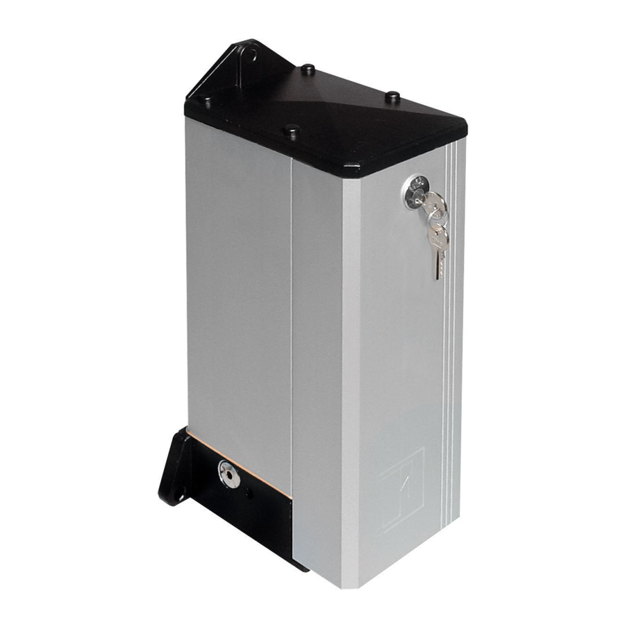
Braking; and eventually they can be fitted with a flow regulator to control and keep constant the speed of the gates during the rotation movements. IMPORTANT: All the above models of DRIVE 700 imply that the gates are fitted with an electric lock in case they are wider than 2 meters. PRELIMINARY INSPECTION OF THE GATE CONDITION... -
Page 3: Preparing The Gate
65 mm PREPARING THE GATE The gate to be operated must be prepared to take the DRIVE 700 mechanism. For a perfect performance of the system, it is most important that the gate is hanged only by the top hinge whereas the mechanism rotation shaft is to provide a seat for the gate and replaces the lower hinge (Pic. - Page 4 - Lay the jack, which is fitted with a guide base plate, on to the ground fixing base plate. - Make sure that the jack, once fitted on to the base plate fixed to the ground, has the shaft straight with the top hinge center line: a “plumb line”...
- Page 5 STRENGTHENING PLATE strictly respected as indicated before. Perfect alignment of the AND THIS TO THE GATE DRIVE 700 shaft with the gate hinge is essential to the correct operation of the gates (Pic.9). FITTING THE MOTOR PUMP UNIT The hydraulic motor pump unit is to be fitted at a suitable distance from the jack so as piping can be as easy as possible in respect of PIC.
- Page 6 - Fix the electro-hydraulic motor pump unit by means of expanding bolts (not included). It is to be fixed close to the gate to operate in the most suitable position considering all the fitting, setting and testing operations involved. FIXING BOLTS - Excavate between the jack and the motor pump (Pic.12) and lay a tube to house the pipes: copper pipes are supplied on request...
-
Page 7: Electric Lock
10)POST-MOUNTED POLO 44 PHOTOCELL RECEIVER BREAKER 11)POLO 44 PHOTOCELL PROJECTOR 4) JUNCTION BOX 12) JUBI 433 EXTERNAL RADIO RECEIVER 5) DRIVE 700 MOTOR PUMP UNIT 13) BIRIO A 8 AERIAL 6) DRIVE 700 JACK 14) PRIT 19 KEYSWITCH 7) POLO 44 PHOTOCELL RECEIVER 15) JUBI 433 TRANSMITTER n°4x1... - Page 8 CCTV etc…, SOLID STATE RELAYS are recommended to be used only. Standard relays would affect the micro-processor. N.W.: THIS PANEL IS TESTED TO OPERATE GATES ONLY THROUGH FADINI ACCESSORIES. NO GUARANTEE FOR ACCESSORIES OF OTHER MAKE OR SPECIAL APPLICATIONS. ALL OPERATIONS OPEN, CLOSE &...
- Page 9 FEATURES OF THE ELECTRONIC PROGRAMMER FOR SWINGING GATES All the electrical connections are to be made as per the following instructions and diagrams. Supply the terminals 24-25 with 230V - 50 Hz single phase voltage. The “red LED” switches on and stays on as long as the board is properly supplied. Through the timer No. 9 you can control the running time of the motor in both cycles, OPEN and CLOSE.
-
Page 10: Features And Technical Specifications
FEATURES AND TECHNICAL SPECIFICATIONS “Elpro 13 CEI” represents the latest state of the art technology for control panels. It is extremely versatile and can meet the most various requirements. It is fitted with the “Cut Off Switch” by cover knob. It has the same functions as “Elpro 9”... -
Page 11: Air Bleeding
PIC. 19 LOCKING FOR MANUAL OPERATIONS BRAKE ADJUSTMENT ie. DAMPENING Should a DRIVE 700 system braking in Open and Close cycles have BRAKE ADJUSTMENT been installed, it is necessary to adjust the brake ie. the dampening SCREW device to slow down speed over the last 40 cm of the gate travel,... -
Page 12: Technical Specifications
The manufacturers reserve the right to change the products without any previous notice and are not liable for possible damages to people and properties. Via Mantova, 177/A - 37053 Cerea (Verona) Italy - Tel. +39 0442 330422 r.a. - Fax +39 0442 331054 - e-mail: info@fadini.net - www.fadini.net...


Need help?
Do you have a question about the DRIVE 700 and is the answer not in the manual?
Questions and answers