
Subscribe to Our Youtube Channel
Related Manuals for Vanco EVMX4X3


Summary of Contents for Vanco EVMX4X3
- Page 1 4K HDBaseT ™ M A T R I X with HDMI Output, IR, IP and RS-232 4K 4x3 HDBaseT™ Matrix Switcher with 1 HDMI Output, IR, IP and RS-232 Part Number: EVMX4X3 www.vanco1.com • 800.626.6445...
- Page 2 DEAR CUSTOMER Thank you for purchasing this product. For optimum performance and safety, please read these instructions carefully before connecting, operating or adjusting this product. Please keep this manual for future reference. This product is 100% inspected and tested in the United States to verify HDMI performance parameters.
-
Page 3: Package Contents
IR control, and an easy to use UI accessible via IP. Control switching sources to displays from a computer or a wireless device such as a tablet or mobile phone. The EVMX4X3 is compatible with both the EVRXHD2 and EVRXDSC HDBaseT receivers for additional flexibility. -
Page 4: Specifications
SPECIFICATIONS Video Input ..............(4) HDMI Video Input Connector ..........(4) Type-A Female HDMI Video HDMI Input Resolution ........Up to 4K@60Hz 4:4:4, HDR10, Dolby Vision Video Output ............. (3) HDBaseT, (1) HDMI Video Output Connector ..........(3) RJ45, (1) Type-A female HDMI Video HDMI Output Resolution ........ - Page 5 SPECIFICATIONS Crosstalk Isolation ............. RCA: < -80 dB, 10KHz sine at 0dBFS level (or max level before clipping); SPDIF: < -70 dB, 10KHz sine at 0dBFS level (or max level before clipping) L+R Level Deviation............ RCA: < 0.3dB, 1KHz sine at 0dBFS level (or max level before clipping) Frequency Response Deviation ........
-
Page 6: Panel Descriptions
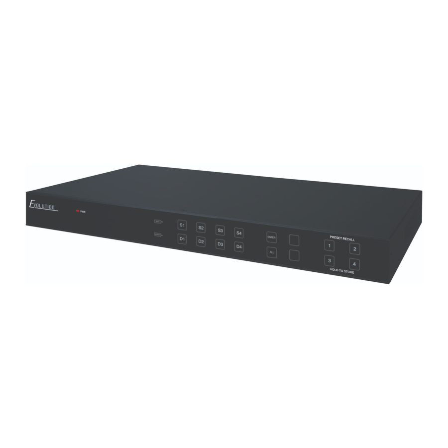
PANEL DESCRIPTIONS Front Panel POWER LED: Illuminates red when the device is in standby mode, illuminates green when device is powered on INPUTS: Inputs 1-4 source selection (buttons will turn blue when selected) OUTPUTS: Outputs 1-4 display selection (buttons will turn blue when selected) Menu Buttons: •... -
Page 7: Rear Panel
Rear Panel INPUTS: Connect HDMI sources to each corresponding HDMI input IR IN: • 1-3: Connect the included IR Receivers (RXs) to each port, the number on the IR input corresponds to the HDBaseT outputs. Connect this if you would like to control the display(s) over HDBaseT (receiver(s) have IR outputs) •... -
Page 8: Connect And Operate
RCA audio breakouts follow output 4 only) OPTIONAL: Connect a router or ethernet switch to the TCP/IP RJ45 jack on the EVMX4X3, this will connect the matrix unit to the network, and can be controlled via IP Connect the included power supply www.vanco1.com... -
Page 9: Front Panel Control
FRONT PANEL CONTROL The EVMX4X3 can be controlled by using the buttons on the front panel. Whenever a command is accepted, the selected input/output buttons will blink three times to confirm. 5.1 Signal Switching (S= Source; D= Display) • Switch an input to an output... -
Page 10: User Interface Control
Press the CLEAR button to cancel USER INTERFACE CONTROL The matrix switcher can be controlled via TCP/IP. Connect the EVMX4X3 to a router or ethernet switch to connect to the local network. The default IP address and settings are: IP Address 192.168.0.178... - Page 11 When using the UI for the first time, an admin password must be set, and then click “Save” to enter the below login tab. Be sure to record the password(s). The UI is available in two formats, one as a master for the integrator and/or admin, and another for end users that restricts access to only switching inputs/outputs: Username Password...
- Page 12 6.1 Switching Tab Use the 4x4 button grid on the page to set which inputs are directed to which outputs. For example, clicking the button on the Input 1 row and Output 1 column, directs input 1 to output 1. Use the 9 numbered buttons under scene area to save and load layout presets.
-
Page 13: Configuration Tab
6.2 Configuration Tab 6.2.1 PoC Setting (you can disable the Power over Cable setting on the EVRXHD2 or EVRXDSC receivers) Turn on or off PoC for 1-HDBT output 6.2.2 EDID Copy Copy the EDID of the selected output device to one or more input source devices 800.626.6445... - Page 14 6.2.2 EDID Setting Select the compatible built-in EDID for the selected one or more input sources. Upload user-defined EDID by the below steps: Prepare the EDID file (.bin) on the control PC. Select the User-defined Click the box and then select the EDID file (.bin) according the tooltip Click Apply to upload the user-defined EDID, and then click Confirm to save setting 6.3 RS-232 Tab 1) Local...
- Page 15 • Local: The RS-232 port of matrix switcher • Baud Rate: 9600 • Command Ending: NULL, CR, LF or CR+LF can be chosen • Command: Type the command in this box to control the third-party device which is connected to the RS- 232 port of the matrix switcher.
-
Page 16: Interface Tab
6.4 Interface Tab • Inputs and outputs can be renamed to make it easier when switching sources to displays. Simply type in the new name for each input/output, then click “Confirm” 6.5 Network Tab • Adjust to Static IP or Dynamic Host Configuration Protocol (DHCP) •... - Page 17 Here you can change the admin password, and lock the front panel” 7 IR Control 7.1 IR Remote Control Connect IR receiver to the IR EYE port on the back of the EVMX4X3, the matrix can be controlled by the included IR remote •...
- Page 18 7.2 IR Pass-through Control The matrix switcher supports bi-directional IR pass-through, allowing the devices to be controlled by both source and display ends. This section provides connection and switching examples to illustrate possible configurations. 7.2.1 Control Local Input Device from Remote The local input source device can be controlled from the remote receiver location.
- Page 19 7.2.2 Control Remote Output Device from Local The remote displays can be controlled from the local matrix switcher location. • Control remote device through IR IN port Example: Switch HDMI input 2 to HDBaseT output 3. Connect an IR receiver to IR IN 3 port on the matrix switcher, then connect an IR emitter to the IR OUT on the receiver, as shown in the diagram below: •...
- Page 20 EVMX4X3 with third party control systems and other IR products to provide a cleaner, faster installation. Eliminates the need to cut and splice wires or tape emitters and receivers together. Simply plug the red connector into the EVMX4X3, and the black connector into the 3rd party control system or IR system.
- Page 21 8.1.2 Control the Matrix Switcher from Remote To control the matrix switcher from a remote location, please connect one or more PCs to the RS-232 ports of HDBaseT receivers with the 3-pin to DB9 RS-232 Cables. The matrix switcher can be controlled by any one of PCs, the connection diagram is shown as below: Note: The command “RS232RCM[X]ON.”...
- Page 22 8.1.4 Control the Local Third-party Device from Remote To control a local third-party device from remote, first determine which HDBaseT receiver is connected to (1 in the diagram below). Next, connect a PC to the RS-232 port of HDBaseT receiver with 3-pin to DB9 RS-232 Cable, then connect a third-party device (e.g.
-
Page 23: Limited Warranty
If repairs are needed during the warranty period the purchaser will be required to provide a sales receipt/sales invoice or other acceptable proof of purchase to the seller of this equipment. The seller will then contact Vanco regarding warranty repair or replacement. - Page 24 ® Vanco International 506 Kingsland Drive Batavia, Illinois 60510 call: 800.626.6445 fax: 630.879.9189 visit: www.vanco1.com...
Need help?
Do you have a question about the EVMX4X3 and is the answer not in the manual?
Questions and answers