
Related Manuals for Vanco Evolution EVMX4K16


Summary of Contents for Vanco Evolution EVMX4K16
- Page 1 HDBaseT™ 16x16 M A T R I X Supports 4K2K @ 60Hz &1080p 3D Signals Vanco Part Number EVMX4K16 HDBaseT™ 16 x 16 Matrix Selector Switch www.vanco1.com • 800.626.6445...
- Page 2 DEAR CUSTOMER Thank you for purchasing this product. For optimum performance and safety, please read these instructions carefully before connecting, operating or adjusting this product. Please keep this manual for future reference. This product is 100% inspected and tested in the United States to verify HDMI performance parameters.
-
Page 3: Package Contents
Receiver unit to be powered without the use of a power supply. The result is an easy and plug and play solution that allows each output with the ability to extend HDMI over long distances in conjunction with the Evolution by Vanco HDBaseT EVRXHD1 receiver (sold separately). -
Page 4: Specifications
SPECIFICATIONS Input ............... 16 HDMI Input Connectors ............Female HDMI Input Level ............... T.M.D.S. 2.9V~3.3V Input Impedance ............100Ω (Differential) Outputs ..............2 HDMI, 14 HDBaseT Output Connectors ............ Female HDMI, Female RJ45(with LED indicators) Output Level ............. T.M.D.S. 2.9V~3.3V Output Impedance ............. -
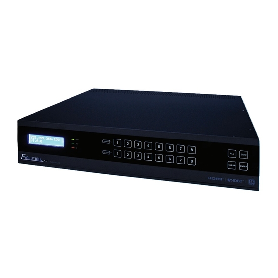
Page 5: Front Panel Descriptions
FRONT PANEL DESCRIPTIONS 1. Firmware: Micro USB port for updating firmware when applicable 2. LCD Screen – displays status 3. Power Indicator – Green: Power On; Red: Standby 4. ACT Indicator – Green: Serial communication is active 5. IR Indicator: feedback for IR, blinks Red when IR signal is received 6. -
Page 6: Back Panel Descriptions
BACK PANEL DESCRIPTIONS 1. HDMI INPUTS: HDMI input ports, 16 in total, connects to source devices 2. IR IN: 16 in total, connect included IR Receivers (IR is routed) - Unit also has bi-directional IR, use IR IN in conjunction with IR OUT on EVRXHD1 receiver to control the display(s) from the matrix unit location 3. -
Page 7: Connection Diagram
CONNECTION DIAGRAM CENTRAL CONTROL SYSTEM iPAD SPEAKERS MATRIX DVD REMOTE REMOTE IR RX IR RX HDTV REMOTE ROUTER EVRXHD1 RECEIVERS IR EMITTER BLU-RAY DVD (SOLD SEPARATELY) HDTV HDTV DVD REMOTE IR EMITTER HDTV HDTV 1. System should be installed in a clean environment and has proper temperature and humidity 2. -
Page 8: Front Panel Button Control
CONNECTION WITH HDBASET POH RECEIVER The EVMX4K16 boasts 14- HDBaseT output ports which support PoH or Power over HDBaseT. Connect the HDBT output ports of the matrix to the HDBaseT Receivers supporting PoH (EVRXHD1) via twisted pair. Plug a power supply to the power port of the matrix and power will be supplied to the accompanying receiver(s) FRONT PANEL BUTTON CONTROL •... - Page 9 EDID The EVMX4K16 features EDID management to maintain compatibility between all devices. It can be controlled via EDID learning and EDID invoking. EDID Learning: • One input port learns the EDID data of one output port: Operation: EDID + INPUT# + OUTPUT# + ENTER Example: Input 1 learns EDID data from output 10: INPUT: OUTPUT:...
- Page 10 • To select an EDID Preset for one input Operation: Long-press EDID for 3 seconds to enter EDID configuration mode, and then press INPUT# + OUTPUT# + ENTER Example: Invoke the first type of embedded EDID for INPUT 4 PRESS INPUT: OUTPUT: (Hold for 3 seconds)
-
Page 11: Remote Control
REMOTE CONTROL 1. INPUTS: - Input channel selection buttons (1-16) 2. OUTPUTS: - Output channel selection buttons (1-16) - Embedded EDID selection buttons (1-6) 3. Menu Buttons: ALL, CLEAR, EDID and ENTER - ALL: Select all input/output channels. - EDID management button: Enable input port to manually capture and learn the EDID data of output devices. - Page 12 The following is the voltage and pinout used for IR of the EVEXHDB1. Due to possible differences in 3rd party IR cables, utilizing the included IR accessories is recommended, any third party IR accessory may not work or can cause damage. Control the EVMX4K16 Connect an IR receiver to the IR EYE port, the EVMX4K16 can be controlled through the included Matrix IR Remote or 3rd party control system.
- Page 13 Example: Switch HDMI input 3 to HDBaseT output 4. Connect one IR Receiver to IR IN 4 port on EVMX4K16, and one IR Emitter to IR OUT 3 port, the connection diagram shown as below: Control the Source(s) from display location(s) Connect IR Receiver(s) to IR IN ports on the HDBaseT Receiver, and IR Emitter(s) to IR OUT ports on the EVMX4K16, and then the local source device (e.g.
- Page 14 Control display(s) from the matrix unit location Connect IR Receiver(s) to IR IN ports on EVMX4K16, and IR Emitter(s) to IR OUT ports on the HDBaseT Receivers, and then the far-end display device (e.g. HDTV) can be control via its IR Remote from local. Connect one IR Receiver to IR IN 4 port on EVMX4K16, Connect one IR Emitter to IR OUT port on HDBaseT Receivers which are connected to HDBaseT output 4 port, and the connection diagram shown as below: www.vanco1.com...
- Page 15 RS232 CONTROL EVMX4K16 features RS232 port which is a 3-pin phoenix connector for RS232 control, and the definition of its pins is listed in the table below. Unused Transmit Receive Unused Ground Unused Unused Unused Unused The RS232 port of EVMX4K16 and HDBaseT Receiver support bi-directional communication, there are three RS232 control modes: •...
-
Page 16: Tcp/Ip Control
TCP/IP CONTROL Control Mode EVMX4K16 features a TCP/IP port for IP control. TCP/IP default settings: Default IP: 192.168.0.178 Gateway: 192.168.0.1 Port: 4001. NOTE: IP & Gateway can be changed as you need, Serial Port cannot be changed. Control via PC/Computer Connect a PC/computer to the TCP/IP port of the EVMX4K16, set its network segment to the same IP information as the default information. - Page 17 Controlled by PC(s) in LAN Connect a router or ethernet switch to the EVMX4K16 via the LAN port (as shown in the following figure). Set the network segment of EVMX4K16 to the same as the router’s, then any PC within the LAN network are able to control the EVMX4K16. Follow these steps to connect the devices: Connect the TCP/IP port of the EVMX4K16 to Ethernet port of PC with Cat5e/6.
- Page 18 There are 2 User Interfaces available: • Admin (default password: admin) • End user (default password: user) The “admin” interface will allow access to more settings and configurations, while the “end user” interface will only give access to switching. Main Menu Interface shown after logging in, provide intuitive I/O connection switching.
- Page 19 Users Menu Click “Users” to enter the below menu: In this section the credentials can be changed and saved, front panel can be locked, and shows which GUI and F/W version the matrix unit has. Main: Interface shown after logging in, provide intuitive I/O connection switching. See the screenshot below: Interface Menu Click “Interface”...
- Page 20 Configuartion Menu Click “Configuration” to enter the below menus: HDCP: Turn on/off HDCP compatible for each input port. (Note: a source that requires HDCP will not work when HDCP is set to OFF) www.vanco1.com...
- Page 21 EDID Copy: One or several input source devices learn EDID from one output display device EDID Setting: One or several input source devices invoke the embedded EDID 800.626.6445...
- Page 22 Network Menu Click “Network” to enter the below menu: Inquiry and configure network settings including MAC address, IP address, subnet mask, and Gateway www.vanco1.com...
-
Page 23: Troubleshooting
TROUBLE-SHOOTING 1. PROBLEM: Color loss or no video signal output. CAUSE: The connecting cables may not be connected correctly or it may be broken. SOLUTION: Check whether the cables are connected correctly and in working condition. 2. PROBLEM: No output image when switching. CAUSE: No signal at the input / output end. Solution: Check with oscilloscope or multi-meter if there is any signal at the input/ output end. - Page 24 4. If you are still encountering issues, attempt the “hot-plug concept. With all of the HDMI cables disconnected, turn on the source and plug in the HDMI cable into it’s output, then power up the Vanco unit and plug the HDMI cable into it’s input, finally turn on the display and plug the HDMI cable from the receiver into it.
-
Page 25: Limited Warranty
If repairs are needed during the warranty period the purchaser will be required to provide a sales receipt/sales invoice or other acceptable proof of purchase to the seller of this equipment. The seller will then contact Vanco regarding warranty repair or replacement. -
Page 26: Technical Support
TECHNICAL SUPPORT In case of problems, please contact Vanco Technical Support by dialing 1-800-626-6445. You can also email technical support issues to techsupport@vanco1.com. When calling, please have the Model Number, Serial Number (affixed to the bottom of the unit) and Invoice available for reference during the call. -
Page 27: Fcc Statement
FCC STATEMENT This equipment generates, uses and can radiate radio frequency energy and, if not installed and used in accordance with the instructions, may cause harmful interference to radio communications. It has been tested and found to comply with the limits for a Class B digital device, pursuant to part 15 of the FCC Rules. These limits are designed to provide reasonable protection against harmful interference in a commercial installation. - Page 28 ® Vanco International 506 Kingsland Drive Batavia, Illinois 60510 call: 800.626.6445 fax: 630.879.9189 visit: www.vanco1.com...
Need help?
Do you have a question about the Evolution EVMX4K16 and is the answer not in the manual?
Questions and answers