FULTON J Series Installation, Operation, Maintenance And Parts Manual
Oil fired steam boilers
Hide thumbs
Also See for J Series:
- Installation, operation and maintenance manual (72 pages) ,
- Installation, operation and maintenance manual (76 pages)

Related Manuals for FULTON J Series


Summary of Contents for FULTON J Series
- Page 1 INSTALLATION, OPERATION, MAINTENANCE AND PARTS MANUAL 'J' SERIES - OIL FIRED STEAM BOILERS (6J - 60J) This Manual must be available to the boiler operator at all times. J OIL-E-10 2008...
- Page 2 Failure to carry out the routine maintenance checks could result in a drastic reduction in the life expectancy of the boiler. Continual improvement in boiler design and fittings may result in some of the components used being different to those in this manual, if in any doubt about individual components or their operation, contact Fulton Service Department. NOTE The Pressure System Safety Regulations 2000 Fulton Boilers fall within the scope of the Pressure Systems Examination Scheme.
-
Page 3: Table Of Contents
LIST OF CONTENTS TITLE SECTION INTRODUCTION General Technical Data INSTALLATION General Siting Ventilation Flue Outlet Water Supply Blowdown Valves Main Steam Valve Steam Safety Valve Water Level Gauge Set Oil Supply 2.10 Electrical Requirements 2.11 Steam Pressure Gauge 2.12 Commissioning the Boiler 2.16 Cleaning Steam Lines and Pressure Vessels 2.17... - Page 4 Do not change the boiler fuel without consulting the Do not try to do repairs or any other maintenance boiler manufacturer. work you do not understand. Obtain a Service Manual from Fulton or call a Fulton Service Engineer WARNINg Non-approved modifications can cause injury and WARNINg damage.
- Page 5 Optional Variations (where fitted) Appendix Spirax High Integrity Level Controls LIST OF ILLUSTRATIONS TITLE FIg. NO. Oil Fired Steam Boiler Boiler Top View Typical Installation Boiler Flue Connection Boiler Feedwater Arrangements Boiler Blowdown (20-60) Boiler Blowdown (6-15) Water Column Sequencing Valve Boiler Top Components Steam Pressure Gauge Nozzle and Ignition Assembly...
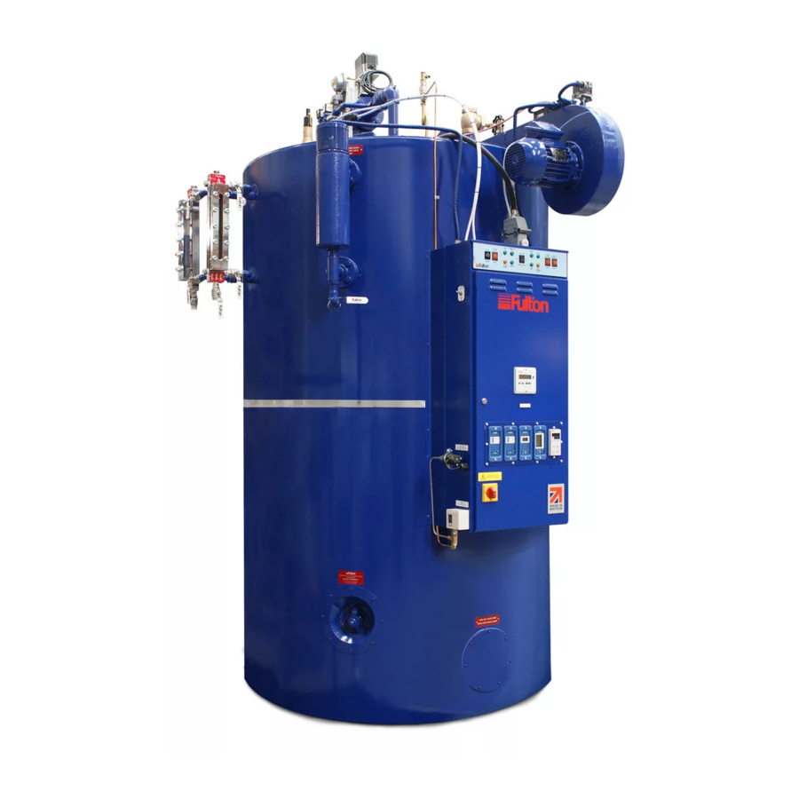
- Page 6 Air Intake Manifold Feed Water to Boiler Steam Supply Valve Pump Water Column Strainer Probes Water Column Feed / Return Lines Boiler Control Panel Cleanout Door Handhole (flue passes and (Pressure Vessel flame turn around) Inspection) FIg.1 OIL FIRED STEAM BOILER J OIL-E-08 2008...
-
Page 7: Introduction
INTRODUCTION SECTION 1 general The Fulton Series J Oil Fired Steam Boiler is a vertical two-pass boiler of simple and efficient design and construction. Every care has been taken in the manufacture of the boiler to ensure that quality and reliability standards are maintained. Satisfactory performance can only be ensured if the installation recommendations, operating routines and maintenance schedules laid out in this manual are adhered to. -
Page 8: Boiler Top View
Flame Main Detector Steam Valve Feed Water and Check Valves Pressure Gauge Ignition Oil Feed Electrodes Steam Pressure Gauge Steam Valve Feed Water Pressure Valves Controllers Ignition Water Level Transformer Probes System Feed Water Supply FIg. 2 BOILER TOP VIEWS J OIL-E-08 2008... -
Page 9: Installation
INSTALLATION SECTION 2 gENERAL The installation of a Series J Oil Fired Steam Boiler should be carried out by competent personnel in accordance with all relevant safety regulations. It is the responsibility of the installer to ensure that these regulations are complied with. SITINg The boiler house should be sufficiently large to allow easy and safe access to all parts of the boiler for installation, operation and maintenance purposes. - Page 10 FIg. 3 TyPICAL INSTALLATION J OIL-E-08 2008...
-
Page 11: Flue Outlet
FLUE OUTLET The boiler is supplied with a stainless steel flue spigot that should be inserted into the flue outlet in the back of the boiler and secured with the three angle clips supplied loose in the trim box. The height and type of flue will generally be subject to local planning regulations and approvals. The following information is intended to provide assistance where the installation of a simple flue is required. Where multi- b oiler flues or difficulties are experienced, specialist advice should be obtained. -
Page 12: Water Supply
Care should be taken to ensure the pipework is properly aligned and not placing any strain upon the feed water pump. Note: The boiler feed water pump may contain an inhibitor and this should be flushed from the pump prior to fitting the pump to the boiler. Failure to do so may result in water bounce or foaming due to the inhibitor forming a seal in the boiler. If the boiler is to be operated with little or no condensate return, consideration should be given to pre-heating the feed water. If in doubt consult Fulton Boiler Works. The Feed water inlet connection on some boilers is located on the left hand side of the boiler below the sight glass assembly. Feed Water Check Feed Water Stop Valve Valve Dip Pipe... -
Page 13: Blowdown Valves
2.6. BLOWDOWN VALVE FIg. 6 BOILER BLOWDOWN (models 20-60) FIg. 6A BOILER BLOWDOWN (models 6 - 15) 2.6.1 BLOWDOWN VALVE - Water Column (Australian boilers only). The valve is a three position isolation valve, each position is indicated on a backing plate mounted with the valve, (the valve is shown in the blowdown position). - Page 14 Oil Supply Flame Detector Location Ignition Electrical Transformer Connection Box Oil Supply Valves Adjustable Ignition Secondary Air Oil Pump Air Control Electrodes Damper Flame Detector Steam Supply Burner Assembly Oil Supply Safety Valve Pipe Connections Water Level Probes Ignition Electrodes FIg.
-
Page 15: Main Steam Valve
MAIN STEAM VALVE The main steam stop valve should be inserted in the steam line approximately 12in. (305 mm) from the top of the boiler. STEAM SAFETy VALVES Safety Valves are factory fitted and preset, they MUST NOT be adjusted. The discharge outlet should be piped to a safe discharge point and the piping so arranged that any condensate trapped in the pipework will drain away from the valve. -
Page 16: Steam Pressure Gauge
2.16 COMMISSIONINg THE BOILER It is essential that the commissioning procedures listed below are carried out by a Fulton Service Engineer who will have the necessary experience and testing equipment to ensure that the installation is not only correct, but is operating safely and at optimum efficiency. - Page 17 2.16 COMMISSIONINg THE BOILER - continued INSPECTION Ensure the boiler has been washed out after installation. Conduct a water analysis before operating the boiler. Examine the probes in the water column and the boiler shell. Replace any damaged probes. Remove the burner and check the electrodes have not been damaged and that their settings are correct. If the burner is fitted with a photocell, remove it and check for damage.
-
Page 18: Commissioning The Boiler
Feed Water Oil Supply Pipes Line Main Steam Valve Main Air Intake Oil Strainer Boiler Data Plate Water Level Sight Gauges Flow / Sight Gauge Return Blowdown Pipes Valves Engineers Test Water Column Button (PM5) Blowdown Valve Control Box Isolator Switch Cleanout Handhole Cleanout Door FIg. - Page 19 2.16 COMMISSIONINg THE BOILER - continued (e) A barometric type draught stabiliser (if fitted in the flue) should be set for a draught of - 0.01in. to - 0.02in. (- 0.025mb to - 0.050 mb) of water column pressure with the burner off. Open all the valves in the water feed line. Open all the valves in the feed water line. FEED PUMP Close the isolating valve on the discharge side of the pump.
-
Page 20: Cleaning Steam Lines And Pressure Vessels
2.16 COMMISSIONINg THE BOILER - continued Adjust the steam pressure control to suit the boiler application. It should be borne in mind that boiler are designed to operate most efficiently at their maximum operating temperature. When boilers are to be operated below a pressure of 80 psi (5.5 bar) consideration should be given to the fitting of a pressure reducing set (see Section 2.8 - Steam Safety Valves). -
Page 21: Operation
OPERATION SECTION 3 gENERAL The following instructions are given for the guidance of the operator in the use of the J Series gas fired boiler and to provide adequate information to ensure that when the boiler is put into use it will be done safely and without risk to health. Where original equipment Service Manuals are supplied, they must be read and understood in conjunction with this manual. -
Page 22: Boiler Controls
BOILER CONTROLS continued. Fuel Pump Mounted on the burner scroll and driven by the burner motor, the fuel pump delivers oil to the burner nozzles at the correct pressure to allow complete atomisation and therefore combustion. PUMP CONTROL Pump Interrupt/Pump Run Switch. Fitted on the left side of the control panel, used to override (switch off) the pump controls during evaporation tests. - Page 23 INDICATOR LIgHTS Indicator lights are fitted to the control panel as an additional aid to the operator. The meaning and operating sequence of these lights is as follows: Start / Low Water Reset This switch is used to start the boiler and to reset the low water alarm. When the switch is pressed to initiate the start-up sequence, the low water alarm lamp also illuminates and the low water audible alarm sounds.
-
Page 24: Filling The Boiler - All Models
FILLINg THE BOILER - ALL MODELS Carry out the following procedure on the initial start up of the boiler and on every subsequent occasion when restarting the boiler after a shut down: Ensure that the main steam stop valve is OPEN. Ensure that the steam pressure gauge isolating valve is OPEN. -
Page 25: Daily Operating Tests
STARTINg THE BURNER - continued. When the boiler has achieved the required (set) pressure, the main steam isolating valve should be slowly opened allowing steam to enter the system distribution pipework. WARNINg The system should be raised to temperature slowly to allow for expansion and to avoid thermal shock and water hammer. - Page 26 3.6.5 2nd. (Overriding) Low Water Check (for boilers fitted with Spirax High Integrity Level Controls, see Appendix 'C') Ensure the following: The burner is firing. The water level is correct in the boiler. The water pump is not running. Switch the pump OFF at the pump override switch. OPEN the main blowdown valve. When the water level nears the bottom of the water level gauge sight glass, the LOW WATER ALARM lamp should illuminate, the low water audible alarm should sound and the burner should stop firing.
-
Page 27: Blowdown Procedures
Keep the boiler, water gauge, water column and interconnecting pipework free from sludge and scale buildup by blowing down in the following manner: Note: Where a boiler is operating continuously at steam pressure, advice should be sort from Fulton regarding the appropriate blowdown procedure. -
Page 28: Evaporation Checks
On completion of the blowdown procedure ensure that all isolation valves are OPEN and all blowdown valves CLOSED. Note: Where a Boiler is operating continuously at steam pressure, advice should be taken from a Fulton agent as to the appropriate blowdown procedure. STEAM WORKING... -
Page 29: Draining The Boiler
DRAININg THE BOILER, Boilers with manual blowdown valves CAUTION Your local regulations could state boiler water above 43 C must not be discharged into the drain. ALWAYS check your local regulations. Ensure the boiler is cold. Isolate the boiler electrics at the isolator on the control box door. Isolate the feed water tank and the feed water pump. -
Page 30: Troubleshooting
3.11 TROUBLESHOOTINg Problem Cause Remedy Ignition Failure 1. Oil tank empty Refill the oil tank. A slight delay in the re-priming of the fuel pump may cause the burner programmer to require resetting before the boiler operates satisfactorily. 2. Power Supply Check fuse or Circuit breaker. Reset or replace as required. 3. - Page 31 3.11 TROUBLESHOOTINg - continued. Problem Cause Remedy Boiler Fails to Start 1. No Power Check fuse or circuit breaker. Reset or replace as necessary. 2. Pressure Control Disconnect all power to the controller. Disconnect the wires from the controller. connect an ohmmeter between the switch terminals.
- Page 32 3.11 TROUBLESHOOTINg - continued. Problem Cause Remedy Poor Combustion 1. Refractory Bricks Check the bricks are not plugged with soot or broken into pieces. Clean and replace as required. 2. Stainless Steel Ring Check to ensure the ring is present and fits securely against the furnace wall. 3. Main Air Adjustment Check air adjustment. Open main air until fire brushes the furnace wall.
- Page 33 Raise the set point and recheck, switch should break. If the controller operates improperly, replace it. 7. Scale buildup in boiler Consult Fulton. 8. Refractory Bricks Check the bricks are not plugged with soot, cracked or broken into pieces. Clean and replace as required.
- Page 34 3.11 TROUBLESHOOTINg - continued. Problem Cause Remedy Boiler is Surging 1. Steam Traps Check traps, clean or replace as required. blowing through. 2. Scale buildup or Call water treatment company and consult lime deposits. the factory. 3. Too much water Dump the return tank and flush the system. treatment. Test the water treatment.
-
Page 35: Pressure Controller
Boiler Ignition Flame Burner Boiler Poor Burner Fault will not Cutoff Failure Failure Combustion Back will not Maintain Fires Maintain Cause Pressure Water Supply Oil Supply Refractories S.S. Ring Ignition Electrodes Oil Nozzle Main Air Adjustment Oil Valves Oil Pump Photoelectric Cell Low Water Probes Low Water Control... -
Page 36: Maintenance Log
This log should be completed regularly as a record of boiler maintenance. MAINTENANCE LOg Date Action Remarks Sig. J OIL-E-08 2008... -
Page 37: Maintenance
SECTION 4 gENERAL To ensure the efficiency of the boiler, carry out the regular maintenance instructions detailed below. If any fault is found during these operations contact your Fulton representative. CAUTION It is essential that regular checks are made to ensure that scale buildup is not taking place within the boiler. Such checks will ensure that water treatment being applied to the boiler feed water is effective. -
Page 38: Daily
The following procedures are designed to prevent the buildup of scale, silt or sludge in the bottom of the boiler, water gauge and water column pipework. In addition to these procedures, the advice of a water treatment specialist should be sought and followed. Note: for boilers fitted with Spirax High Integrity Level Controls see Appendix 'C'. -
Page 39: Monthly
Ensure the main electrical supply is isolated before starting work. Inspect the hand holes in the boiler. If any leakage is evident proceed as follows: Note: Use only genuine Fulton replacement parts. Using the special tee handle wrench, remove the handhole assembly. - Page 40 Handhole Cover Plate Gasket Crab FIg. 18 HANDHOLE Ignition Burner Plate Screws Ignition Leads Transformer Burner Burner Motor Scroll Photocell Air Gate Electrodes Oil Feed Pipe Air Damper Burner Plate Burner Top Plate Oil Line Rubber Spider Coupling Electrode Nozzle Holder Deflector Fuel Pump...
-
Page 41: Six Monthly
SIx MONTHLy (including three monthly) It should be noted that after a Fulton boiler has been in operation for several months, pieces of burned metal will be found in the space at the bottom of the boiler. These pieces of metal are the remains of a light gauge metal form which was used during manufacture for forming the boiler insulation. - Page 42 J OIL-E-08 2008...
- Page 43 Appendix ‘C’ Spirax High Integrity Level Controls The daily testing of boiler water level controls is a mandatory requirement as defined in the Health & Safety Executive Guidance Note PM5. The level of supervision is dependent upon the type of level controls (limiters) fitted. Boilers fitted with self monitoring high integrity controls (limiters) should be tested daily by a qualified boiler at- tendant, but may be supervised during the silent hours and weekends by a Competent Person trained to re- spond to an alarm. Daily testing of the controls is required which can be by simulation, with a weekly test by interrupting the feed water pump and lowering the water by evaporation.
- Page 44 Spirax High Integrity Level Controls, continued. Weekly Test (Daily test plus) 1st. Low Water 1. With the burner firing 2. Switch the pump interrupt switch to the pump interrupt position. 3. By evaporation lower the water level in the boiler until the first low water alarm sounds and the low water indicator lamp illuminates, and the burner shuts down 4.
-
Page 45: General Data
GENERAL DATA SECTION 5 L (dia) FIg. 21 BOILER DIMENSIONS Dimensions (mm) Model 6/8J 2300 2300 2400 2600 2800 3100 3100 3100 1840 1840 1930 2060 2240 2490 2490 2490 1060 1060 1155 1285 1465 1710 1710 1710 1025 1025 1115 1245 1385... - Page 46 WARNINg It is the responsibility of the installer to ensure all parts supplied with the boiler are fitted to the boiler in a correct and safe manner. Connection Sizes (DN) (F=female, M=male) All connections BSP Model 1. Steam Outlet 2. Feed Water 3.
- Page 47 IMPORTANT Recommended Water Conditions It is very important that a strict water management program is followed to ensure trouble free boiler operation. The following are recommended for feedwater and boiler water. FEEDWATER (water entering boiler) pH Value 8.5 to 9.5 tested at room temperature, Hardness less than 2.0 mg/kg in the form of CaCO Suspended Solids...
- Page 48 FIg. 22 BOILER SUPPLy CIRCUIT J OIL-E-08 2008...
- Page 49 FIg. 23 ANCILLARy CONTROL CIRCUIT J OIL-E-08 2008...
- Page 50 FIg. 24 SPIRAx LEVEL CONTROL CIRCUIT J OIL-E-08 2008...
- Page 51 FIg. 25 LC LEVEL CONTROL CIRCUIT J OIL-E-08 2008...
- Page 52 FIg. 26 TDS and BLOWDOWN CONTROL CIRCUIT J OIL-E-08 2008...
- Page 53 FIg. 27 6J - 30J BURNER CONTROL CIRCUIT (Oil Boilers only) J OIL-E-08 2008...
- Page 54 FIg. 28 40J - 60J BURNER CONTROL CIRCUIT (Oil Boilers only) J OIL-E-08 2008...
-
Page 55: Spare Parts
SPARE PARTS SECTION 6 In order to ensure spare parts are correct, please complete the details below and have them at hand when ordering parts or making enquires regarding the boiler. Boiler number Boiler type Type of fuel used Wiring Diagram No. Commissioning Date WARNINg The type, size and lift pressure of the safety valve fitted to a boiler is specific to that boiler. - Page 56 A0-2-1 BOILER, OIL, J OIL-E-08 2008...
- Page 57 A0-2-1 BOILER, OIL, J OIL-E-08 2008...
- Page 58 A1-1-1 BOILER SHELL AND FITTINGS, 6 - 15 (UK and Australia) A1-1-1, 6-15, oil December 2004 J OIL-E-08 2008...
-
Page 59: Boiler Shell And Fittings
A1-1-1 BOILER SHELL AND FITTINgS, 6 - 15 (UK and Australia) Item Part Number Description Remarks Size 10535 Valve, steam stop DN20 6 - 8 10536 Valve, steam stop DN25 10537 Valve, steam stop DN32 10566 Gauge, pressure 4in. x 250psi 6 - 15 SA0001 Gauge, pressure assy. - Page 60 A1-2-1 20/60 June 07 December 2004 J OIL-E-08 2008...
- Page 61 Item Part Number Description Remarks Size 10537 Valve, steam stop DN32 10538 Valve, steam stop DN40 10539 Valve, steam stop DN50 40 - 60 SA0044 Valve, check assembly 20 - 60 11825 Flange 20 - 60 11824 Gasket 20 - 60 14126 Valve, check 20 - 60...
- Page 62 B2-1-1, 12 2004 December 2004 J OIL-E-08 2008...
-
Page 63: Burner Assembly
B2-1-1 BURNER ASSEMBLy, OIL, 6 - 15 Item Part Number Description Remarks Size SA0032 Burner assembly SA0033 Burner assembly SA0034 Burner assembly SA0035 Burner assembly 10285 Adaptor, photocell 6 - 15 3 10290 Sensor, flame 6 - 15 10595 Tube, photocell adaptor 6 - 15 10729 Connector... -
Page 64: Burner Assembly
B2-2-1 BURNER ASSEMBLy, OIL, 20 - 30 10 - 35 B2-2-1 Oil, 20 - 30, 10 2008 December 2004 J OIL-E-08 2008... -
Page 65: Burner Assembly
B2-2-1 BURNER ASSEMBLy, OIL, 20 - 30 Item Part Number Description Remarks Size SA0036 Burner assembly complete SA0037 Burner assembly complete 10285 Adaptor, photocell 20 - 30 3 10290 1 Sensor, flame 20 - 30 10595 Tube, photocell adaptor 20 - 30 10729 Connector 16mm... -
Page 66: Burner Assembly
B2-3-2 BURNER ASSEMBLy, OIL, 40 - 60 7 - 38 B2-3-2 Oil 40 - 60 12 2004 December 2004 J OIL-E-08 2008... - Page 67 B2-3-2 BURNER ASSEMBLy, OIL, 40 - 60 Item Part Number Description Remarks Size SA0041 Burner assembly complete SA0042 Burner assembly complete SA0043 Burner assembly complete 10289 Sensor, flame 40 - 60 SA0012 Lead, ignition assembly 40 - 60 10249 Electrode, angle Rajah 40 - 60 10321 Cable, ignition 40 - 60...
- Page 68 D2-1-1 BURNER SCROLL ASSEMBLY, OIL, 6 - 15 D2-1-1 Oil 6 - 15 12 2004 December 2004 J OIL-E-08 2008...
-
Page 69: Burner Scroll
D2-1-1 BURNER SCROLL ASSEMBLy, OIL, 6 - 15 Item Part Number Description Remarks Size 006EO340 Scroll assembly 6 - 8 010EO340 Scroll assembly 015EO340 Scroll assembly 10239 Transformer 2P 240V 6 - 15 10242 Motor, burner 550W 240/1/50 6 - 15 10247 Motor, burner 250W 2P 415/3/50... -
Page 70: Burner Scroll
D2-2-1 BURNER SCROLL ASSEMBLy, OIL, 20 - 30 D2-2-1, oil, 20-30 12 2004 December 2004 J OIL-E-08 2008... -
Page 71: Burner Scroll
D2-2-1 BURNER SCROLL ASSEMBLy, OIL, 20 - 30 Item Part Number Qty Description Remarks Size 020EO340 Scroll assembly 030EO340 Scroll assembly 10239 Transformer, ignition 2 P 240V 20 - 30 10242 Motor, burner, 550W 240/1/50 20 - 30 10248 Motor, burner, 550W 380-415/3/50 20 - 30 10269... - Page 72 D2-3-1 BURNER SCROLL ASSEMBLy, OIL, 40 - 60 D2-3-1 Oil 40-60 12 2004 December 2004 J OIL-E-08 2008...
- Page 73 D2-3-1 BURNER SCROLL ASSEMBLy, OIL, 40 - 60 Item Part Number Description Remarks Size 050EO340 Scroll assembly 40-50 060EO340 Scroll assembly SA0010 Mesh, air gate 40- 60 10239 Transformer 2P 240V 40- 60 10268 Pump, oil AJ6CE 40- 60 10277 10in.
-
Page 74: Water Column
E1-6-1 WATER COLUMN, 6 - 60 E1-6-1 12 2004 December 2004 J OIL-E-08 2008... - Page 75 E1-6-1 WATER COLUMN, 6 - 60 Item Part Number Description Remarks Size December 2004 J OIL-E-08 2008...
-
Page 76: Water Level Gauge Assembly (350Mm)
F1-4-1 WATER LEVEL gAUgE ASSEMBLy, 6 - 60 350mm and 300mm (Clifton) December 2004 J OIL-E-08 2008... -
Page 77: F1-4-1
F1-4-1 WATER LEVEL gAUgE ASSEMBLy, 6 - 60 350mm and 300mm (Clifton) Item Part Number Description Remarks Size 12444 Gauge, water level assy 350mm centres 6 - 60 12207 Gauge, water level assy 300mm centres 6 - 60 12199 Valve 300 &... - Page 78 G2-1-1 6 - 15 oil 12 2004 December 2004 J OIL-E-08 2008...
- Page 79 Item Part Number Description Remarks Size 004EO322UK Control Box assy 240V/1/50 6 - 15 004EO324UK Control Box assy 400V/3/50 6 - 15 10448 Switch, isolator 25Amp 6 - 15 10496 Contactor 220 - 240V 6 - 15 10507 Contactor, n/open 3ph only 6 - 15 11327...
- Page 80 December 2004 J OIL-E-08 2008...
-
Page 81: Control Box Assembly
Item Part Number Description Remarks Size 020EO324UK Control box assembly 400/3/50 20 - 30 020EO322UK Control box assembly 240/1/50 20 - 30 10448 Switch, isolator 20 - 30 10496 Contactor CI 220 - 240V 20 - 30 10507 Contactor, n/open 3ph only 20 - 30 11327... - Page 82 December 2004 J OIL-E-08 2008...
-
Page 83: Control Box Assembly
Item Part Number Description Remarks Size 050EO324UK Control box assembly 400/3/50 40 - 60 050EO322UK Control box assembly 240/1/50 40 - 60 10448 Switch, isolator 40 - 60 10496 Contactor CI 220 - 240V 40 - 60 10507 Contactor, n/open 40 - 60 11327 Switch, single pole... - Page 84 J OIL-E-08 2008...
- Page 85 H1-1-1 PUMP, FEED WATER Item Part Number Description Remarks Size 14284 Pump assy, 3ph 125psi 8.6bar. 6 - 15 14285 Pump assy, 3ph 125psi 8.6bar. 20 - 30 14285 Pump assy, 3ph 150psi 10.34bar. 6 - 20 14286 Pump assy, 3ph 150psi 10.34bar.
- Page 87 5 year Warranty On the Fulton Boiler Pressure Vessel Fulton Boiler Works (Great Britain) Ltd. will repair or replace FoB factory any Fulton pressure vessel which within five (5) years of the date of delivery is found to be defective in workmanship, or material, provided this equipment is operated and maintained by the buyer for the purpose for which it was designed and in accordance with the Manufacturer’s Handbook.
- Page 88 Fulton Boiler Works (Great Britain) Ltd. Broomhill Road, Bristol, BS4 4TU, England. Telephone 0117 972 3322 Fax: 0117 972 3358 e -mail: uk-info@fulton.com web site: www.fulton.com FM 28400...
Need help?
Do you have a question about the J Series and is the answer not in the manual?
Questions and answers