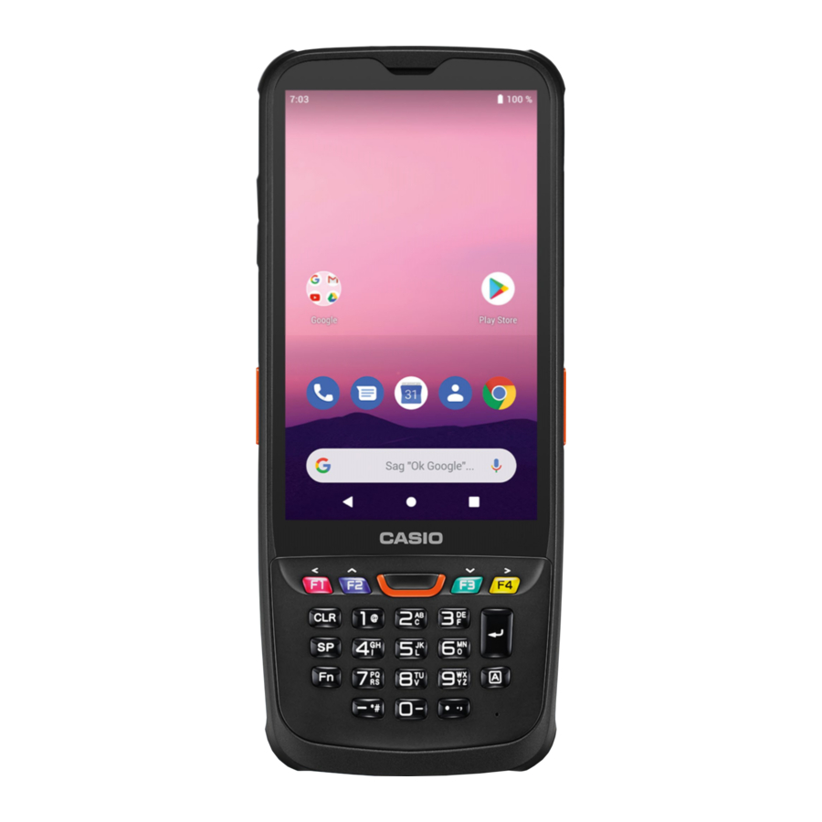
Casio IT-G600 Series User Manual
Rugged smart handheld terminal
Hide thumbs
Also See for IT-G600 Series:
- User manual (41 pages) ,
- Instruction manual (25 pages) ,
- Manual (5 pages)


Need help?
Do you have a question about the IT-G600 Series and is the answer not in the manual?
Questions and answers