Table of Contents
Advertisement
Quick Links
Advertisement
Table of Contents

Related Manuals for socomec SIDER


Summary of Contents for socomec SIDER
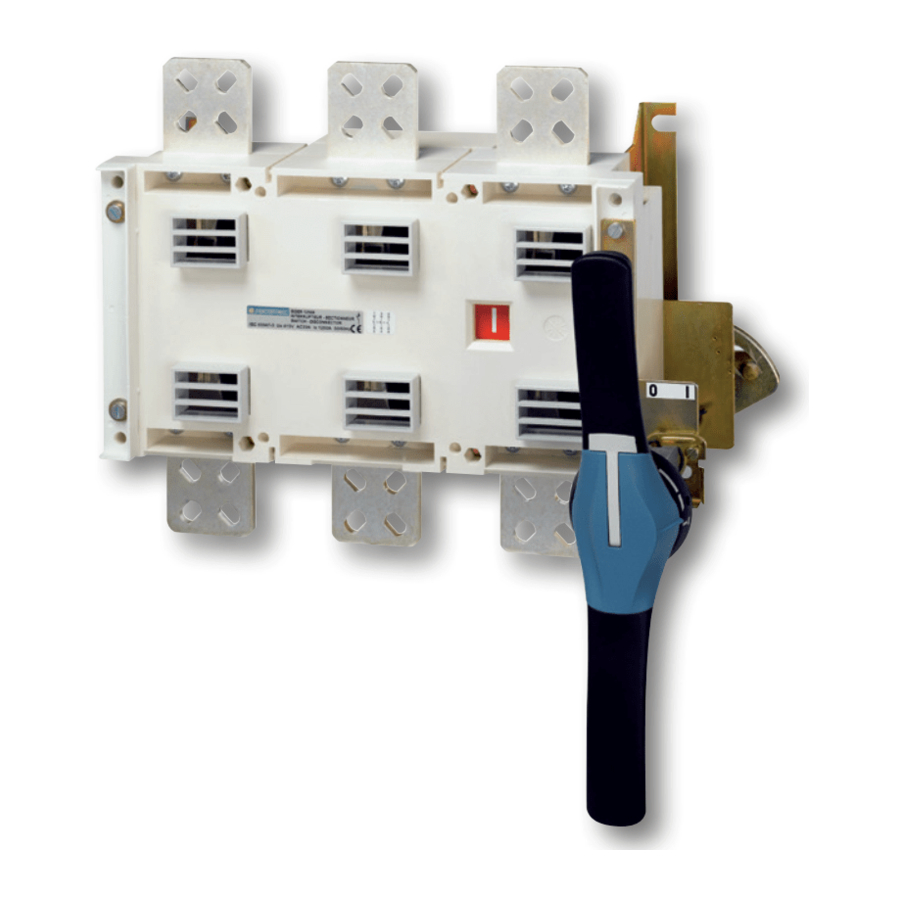
- Page 1 SIDER Visible breaking Switch www.socomec.com...
-
Page 2: Table Of Contents
..............7 3.2. COPPER BAR CONNECTION FOR SIdER FROm 2000 TO 3200 A . -
Page 3: General Safety Instructions
• The SIDER meets the European Directives and Custom Union (EAC) governing this type of product and includes CE and EAC marking on each product. • No covers on the SIDER should be opened (with or without voltage) as there may still be dangerous voltages inside the product such as those from external circuits. -
Page 4: General Overview
2. GENERAL OVERVIEW 2.1. Product introduction 1. Power Section : multipolar load break switch (3 poles) 2. Load break switch terminals 3. Back-plate mounting SIDER fixing lugs 4. Sliders for Terminal Shields 5. Fixing holes for terminal Shields 2.2. Product identification 1. -
Page 5: Environmental
60 °C … 70 °C * Simplified derating method: Ithu ≤ Ith x Kf * A more precise calculation may be done for specific applications. Should this be required please contact SOCOMEC. 2.3.2.2. Hygrometry • 80% humidity without condensation at 55°C •... -
Page 6: Sider References Available
• The Electromagnetic compatibility no. 2004/108/CE dated 15th of December 2004. • Low voltage directive no. 2006/95/CE dated 12th of December 2006. The SIDER complies with CUSTOMS UNION (EAC) technical regulations on: • Electromagnetic compatibility of technical equipment no. TR CU 020/2011 dated 9th December 2011 •... -
Page 7: Installation
ø 12,5 0.19 0.19 1. Terminal screens 0.98 0.98 2. Phase Barriers 1.18 1.18 0.77 0.77 3.54 3.2. Copper bar connection for SIDER from 2000 to 3200 A 2.91 2.91 2.91 2.91 1.46 1.46 1.46 1.46 SIDER - 546 418 A - SOCOMEC... -
Page 8: Mounting Orientation
3.4. Assembly of customer mounted accessories Never handle any customer mounted accessories while there may be the risk of dangeR voltage being or becoming present. 3.4.1. Connection kits for sIdeR from 2000 to 3200 a 708 lb-in 80 Nm Version* Minimum Cu bar Maximal rating without derating n°... -
Page 9: Terminal Screens
3.4.2. terminal screens Top/Bottom B7 (1250 to 1800 A): ref. 1509 3160 Top/Bottom B8 (2000 to 3200 A): ref. 1509 3200 SIDER - 546 418 A - SOCOMEC... -
Page 10: Factory Fitted Accessory
3.5.2. Additional auxiliary contacts for B8 2000 to 3200 A (standard) Pos I Pos I Pos I Intended for pre breaking and signaling of positions I. Up to 2 additional NO/NC auxiliary contacts can be fitted. SIDER - 546 418 A - SOCOMEC... -
Page 11: Connections
• Apply a sufficient progressive action in the direction as indicated on the handle Impossible to padlock • Verify that the SIDER is in 0 position (Padlocking is only possible in 0 position for standard products) SIDER - 546 418 A - SOCOMEC... - Page 12 CORPORATE HQ CONTACT: SOCOMEC SAS 1-4 RUE DE WESTHOUSE 67235 BENFELD, FRANCE www.socomec.com 546 418 A - EN - 09/16...
Need help?
Do you have a question about the SIDER and is the answer not in the manual?
Questions and answers