Table of Contents
Advertisement
Quick Links
Advertisement
Table of Contents

Related Manuals for socomec STATYS series


Summary of Contents for socomec STATYS series
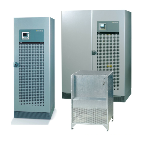
- Page 1 STATYS 200 - 1000A Cabinet and Integrable Frame Operating manual...
-
Page 3: Table Of Contents
Index WArrAnty CertIFICAte SAFety proCedureS 2. 1. oreword 2. 2. recautions 2. 3. lectrical risk 2. 4. isk oF Power cut the role oF StAtyS operAtIng prInCIple operAtIng modeS 5. 1. anual transFer 5. 2. utoMatic transFer 5. 3. utoMatic restart Function 5. - Page 4 SoComeC warranty is strictly limited to the product(s) and does not extend to equipment which may be integrated with this/these product(s), nor the performance of such equipment.
-
Page 5: Oreword
2. 1. F oreword thank you for choosing the StAtyS Static transfer System from SoComeC. this equipment complies with the IeC 62310-2 product standard concerning Static transfer Systems (StS). this equipment conforms to the eC directives applicable to this type of product. this conformity is indicated by the Ce mark: 2. - Page 6 3. the role of StatyS the role of StAtyS is to monitor the alternate source, to detect any failure of the preferred source and, if this should occur, to ensure that the load is automatically transferred to the alternate source. 4.
-
Page 7: Anual Transfer
5. operatIng modeS 5. 1. M anual transFer the user is able to control the transfer of the load from one source to another, both via the keypad and via commu- nication (see "communication interface" § 9). manual transfer does not disturb the supply to the load. If the synchronisation conditions are not met after 30 seconds (factory default setting), an asynchronous transfer oc- curs, if authorised, otherwise the request is cancelled. -
Page 8: Utomatic Restart Function
5. O pEratING mOdES sYnchronous transFer Automatic asynchronous transfer occurs only if it is authorised by the software configuration (standard factory con- figuration, advanced parameters see §10) and if the sources S1 and S2 are not synchronised, e.g. their phase de- viation exceeds the tolerance window. - Page 9 6. functIonal dIagramS Cabinet Integrated Integrable chassis Source 1 Source 2 Source 1 Source 2 Logique de Logique de commande commande Q50-1** Q50-2** STATYS Q50-1** Q50-2** STATYS load load * = optional ** = Q51 and Q52 for Statys 800/1000A legendS: Source 1 input switch*, Source 2 input switch*,...
- Page 10 7. mImIc panel 7. 1. lcd Presentation 7. 1.1. the mimic panel consists of: – an lCd screen permitting: display of electrical magnitudes of an input or output (in Aut mode) • activation of system controls (in Control mode) • display of maintenance codes (in teSt mode) •...
-
Page 11: Password Management
7. m ImIc paNEL 7. 1.2. Meaning of leds BlInKIng load supplied by StAtyS output shutdown imminent output not supplied by StAtyS output supplied directly by source 1 output supplied directly by source 2 general Alarm Critical alarm no alarm active Source outside tolerated Source within tolerances Source absent... - Page 12 7. m ImIc paNEL 7. 1.4. Keypad functIon Accesses different menus (Aut, Control, teSt and prog) once in a menu, cancels an ongoing command In Control mode, activates source 1 conduction Scrolls display, menu or digit In Control mode, stops conduction Scrolls display, menu or digit In Control mode, activates source 2 conduction modifies the blinking value...
- Page 13 7. m ImIc paNEL 7. 1.5. Display the lCd screen displays: the following icons (irrespective of which mode is selected): = indicates the preferred source off = synchronous sources Blinking = sliding sources on = permanently asynchronous sources = password protection is on electrical magnitudes: voltages and frequency of each source on 1 page marked with the number to indicate the source in ques-...
-
Page 14: Operating Modes
7. m ImIc paNEL 7. 1.6. Operating modes there are 4 modes: – automatic (Aut) – control (Control) Whatever the mode selected, STATYS operation remains prioritised. – test (teSt) – programming (prog) press the key to select the next mode (the corresponding led will blink), press the key to enter the se- lected mode. - Page 15 7. m ImIc paNEL Activate source 2 conduction press the key (2), the message "use S2" blinks, press the key to validate this choice or press the key to cancel the command. These changeovers are performed whether the sources are synchronous or asynchronous, unless the factory setting of the device is changed to "synchronous only"...
-
Page 16: Programming Mode
7. m ImIc paNEL 7. 1.9. Test mode this mode enables maintenance codes to be displayed in the form of pages marked with a number For each maintenance page the following information appears: – on the bottom line, the message "StS Code n° xxx" where xxx corresponds to the page n°, –... - Page 17 7. m ImIc paNEL timestamp (user access) display: day time date display: day default value: current day possible choice: day-month-year with day from 1 to 31, month from Jan to dec and year from 00 to 99 time display: time default value: actual hour System configuration (System access) display: sys cfg...
- Page 18 7. m ImIc paNEL Automatic load resupply (System access) display: aut on (automatic on) use of automatic resupply display: aut on (automatic on) default value: no possible choice: yes or no delay before automatic resupply display: dly (delay) default value: 0 seconds possible choice: 0 to 65535 (if aut on = yes) Automatic retransfer to the preferred source (System access) display: aut sb (automatic switchback)
-
Page 19: Alarm Management
7. m ImIc paNEL 7. 1.11. Alarm management When an alarm is triggered (see alarms table), a flashing message (and his number) appears on the screen regard- less of which mode is in use. If the alarm is critical the LED flashes, otherwise it is lit continuously. In addition to the message and the led warning, a buzzer will sound. - Page 20 7. m ImIc paNEL 7. 2. G adicoM raPhic MiMic Panel the graphic mimic panel on the StAtyS door displays information regarding operating status, electrical measure- ments, access to control functions and configuration parameters. It includes a colour graphic display and a luminous status bar, and provides access to: •...
- Page 21 7. m ImIc paNEL 7. 2.1. Mimic panel overview 7. 2.1-1 upper Bar (always displayed). Total output load (A). operating modes (normal or Service during factory setting). Unit status: – Messages displayed: • ON PREFERRED, • ON ALTERNATE, • ON BY-PASS 1, •...
- Page 22 7. m ImIc paNEL 7. 2.1-4 floW dIagram anImatIon. Static Switch 1 output unit output Static Switch 2 output colour of the bar: – blue: active/mains present. – grey: mains not present. priority of colours of the symbols “~” (from highest to lowest): main source 1 –...
- Page 23 7. m ImIc paNEL 7. 2.1-6 StatIc SWItch StatuS. Static Switch Closed Static Switch open 7. 2.1-7 menu IconS. Menu Menu CONTROLS. MONITORING. Menu Help. MEASUREMENTS. STATYS 200-1000A - Ref.:OPMSTA200910-GB_06...
- Page 24 7. m ImIc paNEL 7. 2.2. Mimic panel menu 7. 2.2-1 7. 2.2-2 Legend of symbols. Controls Log file. measurements Status. monitoring help Confirm settings. Cancel Select one of the four menus. home page. Increment 7. 2.2-3 previous page. decrement.
- Page 25 7. m ImIc paNEL 7. 2.3. Entering passwords (when required) 7. 2.3-1 7. 2.3-2 7. 2.3-3 7. 2.3-4 Select the password to be set. • Password to config: protects the MONITORING menu; if set, generates the Control password (user modifiable). •...
- Page 26 7. m ImIc paNEL enter password. 7. 2.3-5 type of character: Cancel character. InS Insert character. 0-9 number Special characters a-Z letters Select the type of character. Quit without Increment value Go to previous Go to next Decrement value Confirm saving or next letter character...
- Page 27 7. m ImIc paNEL 7. 2.3-6 7. 2.3-7 7. 2.3-9 7. 2.3-8 STATYS 200-1000A - Ref.:OPMSTA200910-GB_06...
-
Page 28: Control Menu
7. m ImIc paNEL 7. 2.4. CONTROLS menu this menu is used to send some immediate commands to activate StAtyS operating modes (activate source conduction...). It can also be used to define some STATYS settings (preferred source). Note. The access to configuration and control is protected by password.. •... - Page 29 7. m ImIc paNEL 7. 2.7-2 7. 2.7-3 If StAtyS is stopped, you have access on the two sources, if StAtyS is on one source, you have only access to the other one. 7. 2.7-4 7. 2.7-5 You have to confirm your choice or cancel without saving. If sources are asynchronous, you can force the transfer or waiting for the transfer to occur automatically once the 2 sources become synchronous.
- Page 30 7. m ImIc paNEL 7. 2.7-6 to switch off the load, press on the doWn button, enter button and validate your choice . To cancel this action, valid “Cancel load OFF” with ENTER button. 7. 2.7-7 press on the enter button and validate your choice to modified the preferred source.
- Page 31 7. m ImIc paNEL 7. 2.7-9 MEASUREMENTS menu use up/doWn and leFt/rIght button to navigate between output value and Input value 7. 2.7-10 7. 2.7-11 7. 2.7-12 STATYS 200-1000A - Ref.:OPMSTA200910-GB_06...
- Page 32 7. m ImIc paNEL MONITORING menu 7. 2.7-13 7. 2.7-14 • to modify the password, see on the beginning of this paragraph. • Use “+” and “-” to modify the value selected, “V” to validate and “X” to cancel without saving. 7.
- Page 33 7. m ImIc paNEL 7. 2.7-17 7. 2.7-18 7. 2.7-19 7. 2.7-20 • Use “+” “-” to modify the value selected, “V” to validate and “X” to cancel without saving. STATYS 200-1000A - Ref.:OPMSTA200910-GB_06...
- Page 34 7. m ImIc paNEL 7. 2.7-21 7. 2.7-23 7. 2.7-22 7. 2.7-25 7. 2.7-24 STATYS 200-1000A - Ref.:OPMSTA200910-GB_06...
- Page 35 7. m ImIc paNEL 7. 2.7-26 7. 2.7-27 7. 2.7-28 7. 2.7-29 7. 2.7-30 STATYS 200-1000A - Ref.:OPMSTA200910-GB_06...
-
Page 36: Tart Conditions
8. commISSIonIng 8. 1. s tart conditions - Source 1 and Source 2 voltages are present. In the case of a standard cabinet installation: - switches Q41, Q42, Q30 are open, - inverter Q50 is set to position "0" (or Q51 and Q52 on 0 for Statys 800/1000A). 8. - Page 37 8. c OmmISSIONING 8. 6. “M ” aintenance bYPass return Since each source has its own “maintenance bypass”, two cases may be considered: a. Inverter Q50 is set to position I (or Q51 on 1 for Statys 800/1000A): – Close Q41, –...
- Page 38 HEaD oFFIcE SaLES, MarKETInG anD Your DISTrIBuTor SErvIcE ManaGEMEnT SOCOMEC GROUP SOCOMEC Paris S.A. SOCOMEC capital 10 951 300 € 95, rue Pierre Grange R.C.S. Strasbourg B 548 500 149 F-94132 Fontenay-sous-Bois Cedex B.P. 60010 - 1, rue de Westhouse FRANCE F-67235 Benfeld Cedex - FRANCE Tel.
Need help?
Do you have a question about the STATYS series and is the answer not in the manual?
Questions and answers