
Related Manuals for Rockwell Automation Allen-Bradley 1606-XLE480EP


Summary of Contents for Rockwell Automation Allen-Bradley 1606-XLE480EP
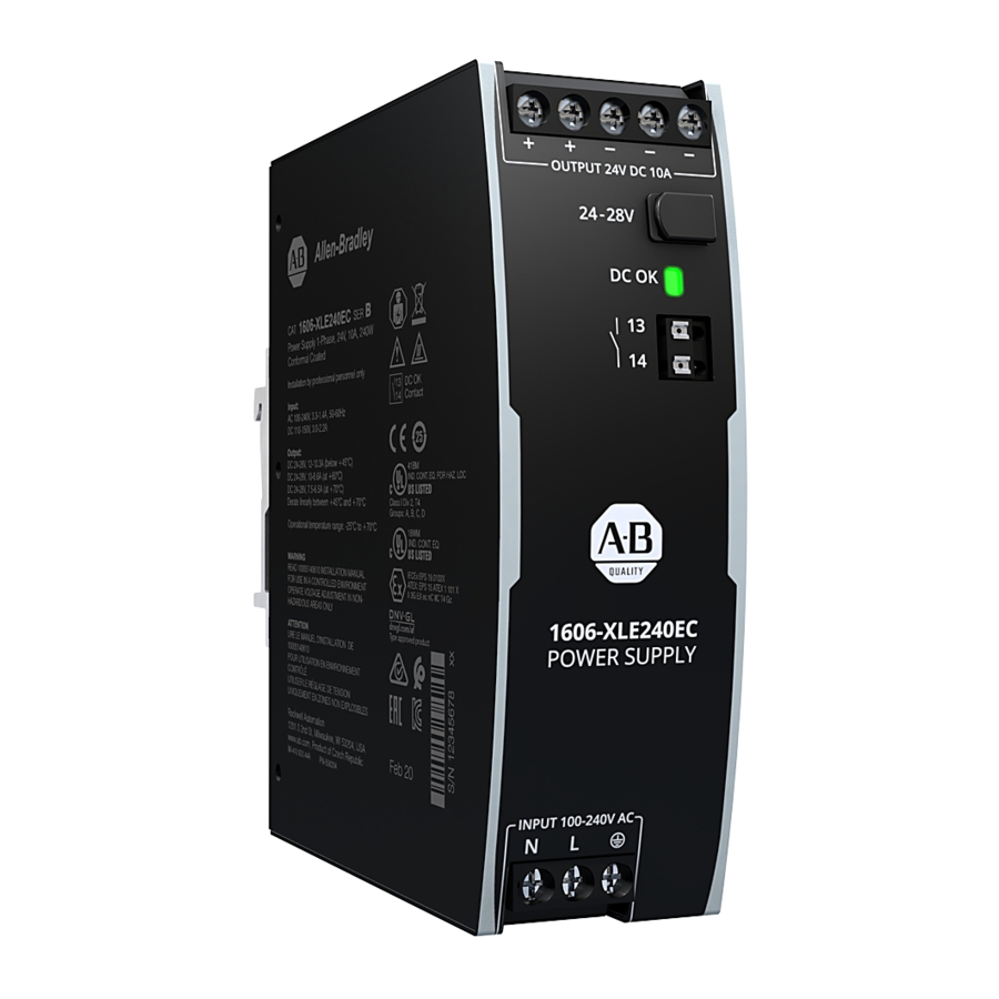
- Page 1 Power Supply - 24V, 20 A, 480 W, Single-phase Input Catalog Numbers 1606-XLE480EP, 1606-XLE480EPC, 1606-XLE480EL, 1606-XLE480EH, 1606-XLE480EM, 1606-XLE480EP-D Reference Manual Original Instructions...
- Page 2 If this equipment is used in a manner not specified by the manufacturer, the protection provided by the equipment may be impaired. In no event will Rockwell Automation, Inc. be responsible or liable for indirect or consequential damages resulting from the use or application of this equipment.
-
Page 3: Table Of Contents
Additional Resources ..........37 Rockwell Automation Publication 1606-RM102A-EN-P - July 2020... - Page 4 Notes: Rockwell Automation Publication 1606-RM102A-EN-P - July 2020...
-
Page 5: Terminology And Abbreviations
Bulletin 1606-XLE480 power supplies have the features and approval ratings to meet the needs of a wide range of applications. Features include a high resistance to transients and power surges, low electromagnetic emission, and DC OK relay contact. Rockwell Automation Publication 1606-RM102A-EN-P - July 2020... - Page 6 Safe Hiccup overload mode • Active power factor correction (PFC) • Minimal inrush current surge • Full power between -25…+60 °C (-13…140 °F) • DC OK relay contact • Current-sharing feature for parallel use Rockwell Automation Publication 1606-RM102A-EN-P - July 2020...
-
Page 7: Specifications
With built-in redundancy 1606-XLE480ERZ With built-in redundancy Mount bracket 1606-XLA-XLE Wall/Panel mount bracket Buffer module 1606-XLSBUFFER24 Buffer module 1606-XLSRED40 Dual redundancy module Redundancy modules 1606-XLSRED4HE Dual redundancy module 1606-XLSREDS40HE Single channel redundancy module Rockwell Automation Publication 1606-RM102A-EN-P - July 2020... -
Page 8: Ac Input
230V Ac a) 100V AC 0.85 b) 120V AC c) 230V AC Output Current Output Current 0.75 8 10 12 14 16 18 20 22 8 10 12 14 16 18 20 22 Rockwell Automation Publication 1606-RM102A-EN-P - July 2020... -
Page 9: Dc Input
375V DC Continuous according to IEC 60664-1 Turn-on voltage 80V DC Steady state value Shut-down voltage Typ 70V DC Steady state value Figure 11 - Wiring for DC Input Battery Power Supply Load Rockwell Automation Publication 1606-RM102A-EN-P - July 2020... -
Page 10: Input Inrush Current
Temperature independent Inrush current 12 A pk 10 A pk 4.5 A pk Temperature independent Inrush energy Temperature independent Figure 12 - Typical turn-on behavior at nominal load and 25 °C (77 °F) ambient Rockwell Automation Publication 1606-RM102A-EN-P - July 2020... -
Page 11: Output
(2) At heavy overloads (when output voltage falls below 13V), the power supply delivers continuous output current for 2 s. Next, the output is switched off for approximately 18 s. Next, a new start attempt is automatically performed. This cycle is repeated as long as the overload exists. If the overload has been cleared, the device operates normally. See Figure 15 on page Rockwell Automation Publication 1606-RM102A-EN-P - July 2020... -
Page 12: Hold-Up Time
Hold-up Time Zero Transition 80 ms Input 24V, 10 A, typ. Voltage 24V, 10 A, min. 24V, 20 A, typ. - 5% Output 24V, 20 A, min. Voltage Hold-up Time Input Voltage 230V AC Rockwell Automation Publication 1606-RM102A-EN-P - July 2020... -
Page 13: Dc Ok Relay Contact
Minimal permissible load: 1 mA at 5V DC Isolation voltage Dielectric Strength on page Figure 19 - DC OK relay contact behavior 0.9* V A DJ < > 100 ms 1 ms 1...4 ms open closed open closed Rockwell Automation Publication 1606-RM102A-EN-P - July 2020... -
Page 14: Remote On/Off Function
25% of the nominal load for 25% of the time 50% of the nominal load for 25% of the time 75% of the nominal load for 25% of the time 100% of the nominal load for 25% of the time Rockwell Automation Publication 1606-RM102A-EN-P - July 2020... -
Page 15: Functional Diagram
Active Inrush Limiter Link for Output Para llel Voltage Temper- Output Output Regulator ature Over- Power Shut- Voltage Manager down Protection DC-ok Output Voltage DC-ok Monitor DC-ok Relay Contact Remote Remote ON/OFF ON/OFF Rockwell Automation Publication 1606-RM102A-EN-P - July 2020... -
Page 16: Front Side And User Elements
DC OK Relay Contact on page 13 for details. Remote ON/OFF Input Pin 15 and 16 must be connected to turn off the power supply. See Remote ON/OFF Function on page 14 for details. Rockwell Automation Publication 1606-RM102A-EN-P - July 2020... -
Page 17: Connection Terminals
Daisy chaining (jumping from one power supply output to the next) is not allowed. Use a separate distribution terminal block as shown in Figure Figure 26 - Using distribution terminals Distribution Terminals Power Power Supply Supply Load Output Output Rockwell Automation Publication 1606-RM102A-EN-P - July 2020... -
Page 18: Lifetime Expectancy
42,000 h 50,000 h At 24V, 20 A and 40 °C (104 °F); Ground Fixed GF40 53,000 h 55,000 h 67,000 h At 24V, 20 A and 25 °C (77 °F); Ground Fixed GF25 Rockwell Automation Publication 1606-RM102A-EN-P - July 2020... -
Page 19: Electromagnetic Compatibility
This device complies with FCC Part 15 rules. Operation is subjected to following two conditions: (1) this device may not cause harmful interference, and (2) this device must accept any interference received, including interference that may cause undesired operation. Rockwell Automation Publication 1606-RM102A-EN-P - July 2020... -
Page 20: Environment
A...85 to 2 64V AC, continuou s B... sho rt term (max. 60 s eve ry 10 minutes) 70°C Altitude 2000 m 6000 m 110 kPa 80 kPa 47 kPa Ambie nt Temperature *) Atmospheric pressure Rockwell Automation Publication 1606-RM102A-EN-P - July 2020... -
Page 21: Safety And Protection Features
At 110V AC, 50 Hz, TN-,TT-mains / IT-mains 0.23 mA / 0.55 mA At 132V AC, 60 Hz, TN-,TT-mains / IT-mains 0.39 mA / 0.94 mA At 264V AC, 50 Hz, TN-,TT-mains / IT-mains Rockwell Automation Publication 1606-RM102A-EN-P - July 2020... -
Page 22: Dielectric Strength
(1) When testing input to DC OK, ensure that the maximal voltage between DC OK and the output is not exceeded (column D). We recommend connecting DC OK pins and the output pins together when performing the test. Rockwell Automation Publication 1606-RM102A-EN-P - July 2020... -
Page 23: Approvals
Council of June 1, 2007 regarding the REACH Directive Registration, Evaluation, Authorization, and Restriction of Chemicals (REACH) IEC/EN 61558-2-16 Safety Isolating Safety Isolating Transformers corresponding to Part (Annex BB) Transformer 2…6 of the IEC/EN 61558 Rockwell Automation Publication 1606-RM102A-EN-P - July 2020... -
Page 24: Physical Dimensions And Weight
Penetration protection Small parts like screws and nuts with a diameter larger than 5 mm (0.20 in.) Figure 30 - Dimensions from Front View Figure 31 - Dimensions from Side view 1606-XLE480EP, 1606-XLE480EPC, 1606-XLE480EM 1606-XLE480EH 1606-XLE480EP-D 1606-XLE480EP-D All dimensions in mm All dimensions in mm Rockwell Automation Publication 1606-RM102A-EN-P - July 2020... -
Page 25: Accessories
Figure 36 - Hole pattern for wall Figure 37 - Power supply mounted on bracket, on bracket, front view mounting left view All dimensions in mm All dimensions in mm All dimensions in mm Rockwell Automation Publication 1606-RM102A-EN-P - July 2020... -
Page 26: 1606-Xlsbuffer24 Buffer Module
A feature of this redundancy module is a special circuit, which keeps the losses and temperature low, even at overload and short circuit conditions up to 65 A continuous current. Parallel Use for Redundancy on page 32 for wiring information. Rockwell Automation Publication 1606-RM102A-EN-P - July 2020... -
Page 27: 1606-Xlsred4He Redundancy Module
22 A. This is typically achieved when the power supply is featured with an intermittent overload behavior (Hiccup Mode). Parallel Use for Redundancy on page 32 for wiring information. Rockwell Automation Publication 1606-RM102A-EN-P - July 2020... -
Page 28: Peak Current Capability
At 40 A for 50 ms, resistive load Peak current voltage dips from 24V to 21V At 100 A for 2 ms, resistive load from 24V to 17V At 100 A for 5 ms, resistive load Rockwell Automation Publication 1606-RM102A-EN-P - July 2020... -
Page 29: Output Circuit Breakers
(1) Remember to consider twice the distance to the load (or cable length) when calculating the total wire length (+ and – wire). Figure 41 - Test circuit Power Supply Load Wire length S1... Fault simulation switch Rockwell Automation Publication 1606-RM102A-EN-P - July 2020... -
Page 30: Use The Power Supply To Charge Batteries
Do not use power supplies in series in mounting orientations other than the standard mounting orientation. Leakage current, EMI, inrush current, and harmonics increase when using multiple devices. Figure 42 - Series operation Unit A Input Output Unit B Load Input Output Rockwell Automation Publication 1606-RM102A-EN-P - July 2020... -
Page 31: Parallel Use To Increase Output Power
Leakage current, EMI, and inrush current increase when using multiple devices. Figure 43 - Parallel use to increase output power Unit A Input Output Unit B Load Input Output Rockwell Automation Publication 1606-RM102A-EN-P - July 2020... -
Page 32: Parallel Use For Redundancy
Module Power Power Supply Supply Output Input Input L N PE L N PE 20 A Load Alternatively, the 1606-XLSRED4HE redundancy module can be used, but has the input and output terminals reversed. Rockwell Automation Publication 1606-RM102A-EN-P - July 2020... -
Page 33: N+1 Redundancy
Input Input L N PE L N PE L N PE L N PE 60 A Load Alternatively, the 1606-XLSRED4HE redundancy module can be used, but has the input and output terminals reversed. Rockwell Automation Publication 1606-RM102A-EN-P - July 2020... -
Page 34: Operation On Two Phases
24V, 20 A; (=100%) Temperature inside the box 51.7 °C (125.06 °F) 55.8 °C (132.44 °F) Temperature outside the 25.9 °C (78.62 °F) 25.6 °C (78.08 °F) Temperature rise 25.8 K 30.2 K Rockwell Automation Publication 1606-RM102A-EN-P - July 2020... -
Page 35: Mounting Orientations
Figure 50 - Mounting orientation D (horizontal cw) Allowed Output Current at 24V 24 A 13 A +70°C Ambient Temperature Mounting orientation E (horizontal ccw) Allowed Output Current at 24V 24 A 13 A +70°C Ambient Temperature Rockwell Automation Publication 1606-RM102A-EN-P - July 2020... - Page 36 Notes: Rockwell Automation Publication 1606-RM102A-EN-P - July 2020...
-
Page 37: Additional Resources
Power Supply - 24V, 20 A, 480 W, Single-phase Input Reference Manual Original Instructions Additional Resources These documents contain additional information concerning related products from Rockwell Automation. Resource Description Switched Mode Power Supply Specifications Technical Data, publication Provides specifications for Bulletin 1606-XL, -XLE, -XLP, and -XLS products and applications. - Page 38 At the end of life, this equipment should be collected separately from any unsorted municipal waste. Rockwell Automation maintains current product environmental information on its website at rok.auto/pec. Allen-Bradley, expanding human possibility, and Rockwell Automation are trademarks of Rockwell Automation, Inc. Trademarks not belonging to Rockwell Automation are property of their respective companies.
Need help?
Do you have a question about the Allen-Bradley 1606-XLE480EP and is the answer not in the manual?
Questions and answers