
Related Manuals for Rockwell Automation Allen-Bradley 1606-XLE192BM


Summary of Contents for Rockwell Automation Allen-Bradley 1606-XLE192BM
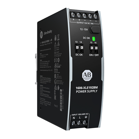
- Page 1 Power Supply - 12V, 16 A, 192 W, Single-phase Input Catalog Numbers 1606-XLE192BM, 1606-XLE192BDM Reference Manual Original Instructions...
- Page 2 If this equipment is used in a manner not specified by the manufacturer, the protection provided by the equipment may be impaired. In no event will Rockwell Automation, Inc. be responsible or liable for indirect or consequential damages resulting from the use or application of this equipment.
-
Page 3: Table Of Contents
Additional Resources ..........31 Rockwell Automation Publication 1606-RM113A-EN-P - September 2020... - Page 4 Notes: Rockwell Automation Publication 1606-RM113A-EN-P - September 2020...
-
Page 5: Terminology And Abbreviations
45 °C (113 °F). They can deliver three times the nominal output current for at least 12 ms, which helps to trip fuses on faulty output branches. Rockwell Automation Publication 1606-RM113A-EN-P - September 2020... -
Page 6: Specifications
600 g (1.3 lb) — Catalog Numbers Catalog Numbers Descriptions 1606-XLE192BM Power supply without extended DC input 1606-XLE192BDM Power supply with extended DC input 1606-XLA-S44 Side mount bracket 1606-XLA-XLE Wall or panel mount bracket Rockwell Automation Publication 1606-RM113A-EN-P - September 2020... -
Page 7: Ac Input
Input Current, typ Power Factor, typ 0.95 a) 100V AC b) 120V AC c) 230V AC (a) 100V AC 0.85 (b) 120V AC (c) 230V AC Output Current Output Current 0.75 20 A 20 A Rockwell Automation Publication 1606-RM113A-EN-P - September 2020... -
Page 8: Dc Input
• Connect + pole to L and – pole to N. • Connect the PE terminal to an earth wire or to the machine ground. Rockwell Automation Publication 1606-RM113A-EN-P - September 2020... -
Page 9: Input Inrush Current
Output voltage 10V/DIV Figure 9 - Typical Turn-on Behavior at Nominal Load, 230V AC Input, and 25 °C (77 °F) Ambient 50 ms/DIV Input current 2 A/DIV Input voltage 500V/DIV Output voltage 10V/DIV Rockwell Automation Publication 1606-RM113A-EN-P - September 2020... -
Page 10: Output
Output Current Output Current 35 A 80 A PLUS Figure 12 - Short-circuit on Output, Hiccup Mode, Typ Output Current Normal Normal Short -circuit operation operation 23 A 18 s 18 s 18 s Rockwell Automation Publication 1606-RM113A-EN-P - September 2020... -
Page 11: Hold-Up Time
Minimal permissible load 1 mA at 5V DC Isolation voltage Dielectric Strength on page Figure 15 - DC OK Relay Contact Behavior 0.9* V < > 100 ms 1 ms 1 ms open closed open closed Rockwell Automation Publication 1606-RM113A-EN-P - September 2020... -
Page 12: Remote On/Off Function
Pulses shorter than 1 s will be extended to 1 s A: Turn-on delay. See Figure 4 on page B: Rise time. See Figure 4 on page C: No active discharge of the output after switch-off. Rockwell Automation Publication 1606-RM113A-EN-P - September 2020... -
Page 13: Efficiency And Power Losses
Figure 20 - Efficiency Versus Input Voltage at 12V, 16 A, Typ Figure 21 - Losses Versus Input Voltage at 12V, 16 A, Typ Efficiency Power Losses 20 W Input Voltage Input Voltage 264V AC 264V AC Rockwell Automation Publication 1606-RM113A-EN-P - September 2020... -
Page 14: Lifetime Expectancy
Converter Input Rectifier Converter Inrush Current Limiter DC OK Status Indicator DC OK DC OK Temper- Output Relay Contact Output ature Over- Power Shut- Voltage Manager down Protection Remote ON / OFF (Shut-down) Rockwell Automation Publication 1606-RM113A-EN-P - September 2020... -
Page 15: Terminals And Wiring
Figure 23 - Daisy Chaining of Outputs Figure 24 - Using Distribution Terminals Distribution Terminals Power Power Supply Supply Power Power Supply Supply Load Load Output Output Output Output max 25 A continuous Rockwell Automation Publication 1606-RM113A-EN-P - September 2020... -
Page 16: Front Side And User Elements
DC OK Relay Contact (quick-connect spring-clamp terminals) Monitors the output voltage of the running power supply. See DC OK Relay Contact on page 11 for details. Input Terminals (screw terminals) N, L Line input PE (Protective Earth) input Rockwell Automation Publication 1606-RM113A-EN-P - September 2020... -
Page 17: Electromagnetic Compatibility
(2) Tested with constant current loads, non-pulsing Switching frequency information is provided in the following table. Attributes Values Notes PFC converter 110 kHz Fixed frequency Main converter 84…140 kHz Output load dependent Auxiliary converter 60 kHz Fixed frequency Rockwell Automation Publication 1606-RM113A-EN-P - September 2020... -
Page 18: Environment
Metal Oxide Input transient protection For protection values, see Electromagnetic Compatibility on page Varistor (MOV) Internal input fuse Included Non-user-replaceable, slow-blow, high-braking capacity fuse Rockwell Automation Publication 1606-RM113A-EN-P - September 2020... -
Page 19: Safety Features
(1) When testing input to DC OK, ensure that the max voltage between DC OK and the output is not exceeded (column D). We recommend connecting DC OK pins and the output pins together when performing the test. Rockwell Automation Publication 1606-RM113A-EN-P - September 2020... -
Page 20: Approvals
REACH Directive June 1, 2007 regarding the Registration, Evaluation, Authorization, and Restriction of Chemicals (REACH) IEC/EN 61558-2-16 Safety Isolating Transformers corresponding to Part 2-6 of the Safety Isolating (Annex BB) Transformer IEC/EN 61558 Transformer Rockwell Automation Publication 1606-RM113A-EN-P - September 2020... -
Page 21: Physical Dimensions And Weight
5 mm (0.20 in.) to 15 mm (0.59 in.). Figure 30 - Front View Figure 31 - Side View All dimensions in mm Rockwell Automation Publication 1606-RM113A-EN-P - September 2020... -
Page 22: Wall Or Panel Mount Bracket
Figure 33 - Right Front Isometric View Figure 34 - Right Back Isometric View Figure 35 - Wall/Panel Mounting, Front View Figure 36 - Hole Pattern for Wall Mounting Figure 37 - Wall/Panel Mounting, Side View Rockwell Automation Publication 1606-RM113A-EN-P - September 2020... -
Page 23: Side Mount Bracket
Due to the low power losses, the unit is slender and only requires 36 mm (1.42 in.) width on the DIN rail. Rockwell Automation Publication 1606-RM113A-EN-P - September 2020... -
Page 24: Peak Current Capability
Peak current voltage dips Typically dips from 12V to 7.4V At 80 A for 2 ms with resistive load Typically dips from 12V to 7.1V At 80 A for 5 ms with resistive load Rockwell Automation Publication 1606-RM113A-EN-P - September 2020... -
Page 25: Back-Feeding Loads
3 m (9 ft) 3 m (9 ft) 4 m (13 ft) S1: Fault simulation switch B-13 A 1 m (3 ft) 2 m (6 ft) 3 m (9 ft) 4 m (13 ft) Rockwell Automation Publication 1606-RM113A-EN-P - September 2020... -
Page 26: Parallel Use To Increase Output Power
(terminals on bottom of the unit) • altitude Leakage current, EMI, inrush current, and harmonics increase when using multiple power supplies. Figure 44 - Parallel Use to Increase Output Power Unit A Unit B Load Rockwell Automation Publication 1606-RM113A-EN-P - September 2020... -
Page 27: Parallel Use For Redundancy
(± 100 mV) or leave the output voltages of all units at the factory setting. Figure 45 - 1+1 Redundant Configuration with One 1606-XLSRED4HE Redundancy Module Load Failure Monitor optional Output Output Output Power Power Supply Supply Redundancy Module Input Input Input Input Rockwell Automation Publication 1606-RM113A-EN-P - September 2020... -
Page 28: Series Operation
40 °C (104 °F). • The return current to the power supply (battery discharge current) is 2.6 mA typ when the power supply is switched off (except when a blocking diode is used). Rockwell Automation Publication 1606-RM113A-EN-P - September 2020... -
Page 29: Operation On Two Phases
24.6 °C (76.28 °F) 25.7 °C (78.26 °F) 24.4 °C (75.92 °F) 26.0 °C (78.8 °F) Temperature rise 22.8 K (41.04 °F) 30.6 K (55.08 °F) 21.8 K (39.24 °F) 27.4 K (49.32 °F) Rockwell Automation Publication 1606-RM113A-EN-P - September 2020... -
Page 30: Mounting Orientations
Horizontal with Input on the Left Ambient Temperature 60 °C Output Current 20 A 15 A Figure 52 - Mounting Orientation E: 10 A Horizontal with Input on the Right Ambient Temperature 60 °C Rockwell Automation Publication 1606-RM113A-EN-P - September 2020... -
Page 31: Additional Resources
Power Supply - 12V, 16 A, 192 W, Single-phase Input Reference Manual Additional Resources These documents contain additional information concerning related products from Rockwell Automation. Resource Description Switched Mode Power Supply Specifications Technical Data, publication Provides specifications for Bulletin 1606 products and applications. - Page 32 At the end of life, this equipment should be collected separately from any unsorted municipal waste. Rockwell Automation maintains current product environmental information on its website at rok.auto/pec. Allen-Bradley, expanding human possibility, and Rockwell Automation are trademarks of Rockwell Automation, Inc. Trademarks not belonging to Rockwell Automation are property of their respective companies.
Need help?
Do you have a question about the Allen-Bradley 1606-XLE192BM and is the answer not in the manual?
Questions and answers