
Related Manuals for Rockwell Automation Allen-Bradley 1606-XLE260F


Summary of Contents for Rockwell Automation Allen-Bradley 1606-XLE260F
- Page 1 Power Supply - 48V, 5.4 A, 260 W, Single-phase Input Catalog Number 1606-XLE260F Reference Manual Original Instructions...
- Page 2 If this equipment is used in a manner not specified by the manufacturer, the protection provided by the equipment may be impaired. In no event will Rockwell Automation, Inc. be responsible or liable for indirect or consequential damages resulting from the use or application of this equipment.
-
Page 3: Table Of Contents
Additional Resources ..........33 Rockwell Automation Publication 1606-RM112A-EN-P - September 2020... - Page 4 Notes: Rockwell Automation Publication 1606-RM112A-EN-P - September 2020...
-
Page 5: Terminology And Abbreviations
All parameters in this document are specified under the following conditions unless otherwise noted: • 48V, 5.4 A output load • 230V AC, 50 Hz input voltage • 25 °C (77 °F) ambient temperature • after a 5 minutes run-in time Rockwell Automation Publication 1606-RM112A-EN-P - September 2020... -
Page 6: Product Overview
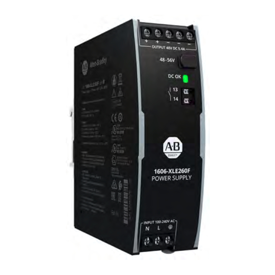
Safe Hiccup Overload mode • Active power factor correction (PFC) • Minimal inrush current surge • Full power between -25…+60 °C (-13…+140 °F) • DC OK relay contact Figure 1 - 1606-XLE260F Power Supply Rockwell Automation Publication 1606-RM112A-EN-P - September 2020... -
Page 7: Specifications
Size (w x h x d) Without DIN rail (1.54 x 4.88 x 4.61 in.) Weight 600 g (1.3 lb) — Catalog Numbers Catalog Numbers Descriptions 1606-XLE260F Power supply 1606-XLA-XLE Wall/panel mount bracket 1606-XLA-S44 Side mount bracket Rockwell Automation Publication 1606-RM112A-EN-P - September 2020... -
Page 8: Ac Input
Input Current, typ 0.95 a) 100V AC b) 120V AC c) 230V AC (a) 100V AC, 0.85 (b) 120V AC, (c) 230V AC Output Current Output Current 0.75 0.5 1 0.5 1 5 5.5 Rockwell Automation Publication 1606-RM112A-EN-P - September 2020... -
Page 9: Dc Input
Figure 8 - Derating Requirements for DC Input Allowed Output Current at 48V Battery Power Supply 5.4 A A: below 60°C ambient temperature Load B: below 55°C ambient temperature C: below 45°C ambient temperature 93.5 187V DC DC Input Voltage Rockwell Automation Publication 1606-RM112A-EN-P - September 2020... -
Page 10: Input Inrush Current
Output voltage 40V/DIV Figure 10 - Typical Turn-on Behavior at Nominal Load, 230V AC Input, and 25 °C (77 °F) Ambient 50 ms/DIV Input current 2 A/DIV Input voltage 500V/DIV Output voltage 40V/DIV Rockwell Automation Publication 1606-RM112A-EN-P - September 2020... -
Page 11: Output
Output Current Output Current 10 A 25 A PLUS Figure 13 - Short-circuit on Output, Hiccup Mode, Typ Output Current Normal Normal Short -circuit operation operation 18 s 18 s 18 s Rockwell Automation Publication 1606-RM112A-EN-P - September 2020... -
Page 12: Hold-Up Time
Minimal permissible load: 1 mA at 5V DC Isolation voltage Dielectric Strength on page Figure 16 - DC OK Relay Contact Behavior 0.9* V < > 100 ms 1 ms 1 ms open closed open closed Rockwell Automation Publication 1606-RM112A-EN-P - September 2020... -
Page 13: Efficiency And Power Losses
Figure 19 - Efficiency Versus Input Voltage at 48V, 5.4 A, Typ Figure 20 - Losses Versus Input Voltage at 48V, 5.4 A, Typ Efficiency Power Losses 22 W Input Voltage Input Voltage 264V AC 264V AC Rockwell Automation Publication 1606-RM112A-EN-P - September 2020... -
Page 14: Lifetime Expectancy
Input Rectifier Converter Inrush Current Limiter Output Voltage Regulator DC OK Temper- Output Output Output Status Indicator ature Over- Power Voltage Shut- Voltage Manager DC OK Monitor DC OK down Protection Relay Contact Rockwell Automation Publication 1606-RM112A-EN-P - September 2020... -
Page 15: Terminals And Wiring
Figure 22 - Daisy Chaining of Outputs Figure 23 - Using Distribution Terminals Distribution Terminals Power Power Power Power Supply Supply Supply Supply Load Load Output Output Output Output max 25 A continuous Rockwell Automation Publication 1606-RM112A-EN-P - September 2020... -
Page 16: Front Side And User Elements
On when the output voltage is >90% of the adjusted output voltage. DC OK Relay Contact (spring-clamp terminals) Monitors the output voltage of the running power supply. See DC OK Relay Contact on page 12 for details. Rockwell Automation Publication 1606-RM112A-EN-P - September 2020... -
Page 17: Electromagnetic Compatibility
(2) Tested with constant current loads, non-pulsing. Switching frequency information is provided in the following table. Attributes Values Notes PFC converter 110 kHz Fixed frequency Main converter 85…140 kHz Dependent on output load Auxiliary converter 60 kHz Fixed frequency Rockwell Automation Publication 1606-RM112A-EN-P - September 2020... -
Page 18: Environment
Figure 26 - Output Current Versus Altitude Allowed Output Current at 48V Allowed Output Current at 48V A: 90...264V AC, continuous B: short term 70 °C 2000 m 4000 m 6000 m Ambient Temperature Altitude Rockwell Automation Publication 1606-RM112A-EN-P - September 2020... -
Page 19: Protection Features
At 110V AC, 50 Hz, TN-,TT-mains / IT-mains Max 0.26 mA / 0.61 mA At 132V AC, 60 Hz, TN-,TT-mains / IT-mains Max 0.44 mA / 1.05 mA At 264V AC, 50 Hz, TN-,TT-mains / IT-mains Rockwell Automation Publication 1606-RM112A-EN-P - September 2020... -
Page 20: Dielectric Strength
(1) When testing input to DC OK, ensure that the max voltage between DC OK and the output is not exceeded (column D). We recommend connecting DC OK pins and the output pins together when performing the test. Rockwell Automation Publication 1606-RM112A-EN-P - September 2020... -
Page 21: Approvals
Council of June 1, 2007 regarding the Registration, Evaluation, Authorization, and Restriction of Chemicals (REACH) IEC/EN 61558-2-16 Safety Isolating Safety Isolating Transformers corresponding to Part 2-6 of the (Annex BB) IEC/EN 61558 Transformer Rockwell Automation Publication 1606-RM112A-EN-P - September 2020... -
Page 22: Physical Dimensions And Weight
DIN rail mounting, the removed aluminum brackets and the black plastic slider must be mounted on the steel bracket. Figure 30 - Side Mounting with DIN Rail Brackets Figure 31 - Side Mounting without DIN Rail Brackets Rockwell Automation Publication 1606-RM112A-EN-P - September 2020... -
Page 23: Wall/Panel Mount Bracket
Figure 33 - Right Front Isometric View Figure 34 - Right Back Isometric View Figure 35 - Wall/Panel Mounting, Front View Figure 36 - Hole Pattern for Wall Mounting Figure 37 - Wall/Panel Mounting, Side View Rockwell Automation Publication 1606-RM112A-EN-P - September 2020... -
Page 24: Redundancy Modules
Redundancy Module Redundancy Module Power Supply Power Supply Power Supply Power Supply Output L N PE L N PE L N PE L N PE 48V, 5 A 48V, 5 A Load Load Rockwell Automation Publication 1606-RM112A-EN-P - September 2020... -
Page 25: Peak Current Capability
If an external fuse is used, minimum requirements must be considered to avoid nuisance tripping of the circuit breaker. A minimum value of 6 A B- or C- Characteristic breaker should be used. Rockwell Automation Publication 1606-RM112A-EN-P - September 2020... -
Page 26: Back-Feeding Loads
109 m (357 ft) C-3A 13 m (42 ft) 24 m (78 ft) 28 m (91 ft) 42 m (137 ft) Figure 43 - Test Circuit Power Supply Load Wire length S1: Fault simulation switch Rockwell Automation Publication 1606-RM112A-EN-P - September 2020... -
Page 27: Parallel Use To Increase Output Power
(terminals on bottom of the unit) • altitude Leakage current, EMI, inrush current, and harmonics increase when using multiple power supplies. Figure 44 - Parallel Use to Increase Output Power Unit A Unit B Load Rockwell Automation Publication 1606-RM112A-EN-P - September 2020... -
Page 28: Parallel Use For Redundancy
Failure Monitor - - - - - - Input Input 48-56V 48-56V DC OK DC OK Redundancy Module Power Supply Power Supply Output L N PE L N PE 48V, 5 A Load Rockwell Automation Publication 1606-RM112A-EN-P - September 2020... -
Page 29: Series Operation
If very large capacitors, such as electric double layer capacitors Loads (EDLCs or “UltraCaps”) with a capacitance larger than 0.5 F, are connected to PLUS the output, the unit might charge the capacitor in the Hiccup mode (see Output on page 11). Rockwell Automation Publication 1606-RM112A-EN-P - September 2020... -
Page 30: Charging Of Batteries
The power supply can also be used on two-phases of a three-phase-system. Such a phase-to-phase connection is allowed as long as the supplying voltage is below 240V+10%. Figure 47 - Operation On Two Phases Power Supply Center Rockwell Automation Publication 1606-RM112A-EN-P - September 2020... -
Page 31: Use In A Tightly Sealed Enclosure
24.1 °C (75.38 °F) 25.4 °C (77.72 °F) 23.9 °C (75.02 °F) 25.0 °C (77 °F) Temperature rise 19.6 K (35.28 °F) 23.2 K (41.76 °F) 17.0 K (30.6 °F) 20.0 K (36 °F) Rockwell Automation Publication 1606-RM112A-EN-P - September 2020... -
Page 32: Mounting Orientations
Figure 51 - Mounting Orientation D: Horizontal with Input on the Left Ambient Temperature 60 °C Output Current Figure 52 - Mounting Orientation E: Horizontal with Input on the Right Ambient Temperature 60 °C Rockwell Automation Publication 1606-RM112A-EN-P - September 2020... -
Page 33: Additional Resources
Power Supply - 48V, 5.4 A, 260 W, Single-phase Input Reference Manual Additional Resources These documents contain additional information concerning related products from Rockwell Automation. Resource Description Switched Mode Power Supply Specifications Technical Data, publication Provides specifications for Bulletin 1606 products and applications. - Page 34 At the end of life, this equipment should be collected separately from any unsorted municipal waste. Rockwell Automation maintains current product environmental information on its website at rok.auto/pec. Allen-Bradley, expanding human possibility, and Rockwell Automation are trademarks of Rockwell Automation, Inc. Trademarks not belonging to Rockwell Automation are property of their respective companies.
Need help?
Do you have a question about the Allen-Bradley 1606-XLE260F and is the answer not in the manual?
Questions and answers