
Related Manuals for SEA ALPHA Series


Summary of Contents for SEA ALPHA Series
- Page 1 International registered trademark n. 2.777.971 ALPHA SATANDARD/PLUS INSTALLATION MANUALS AND SAFETY INFORMATION 67410247 REV 03 - 05/2011...
-
Page 2: Table Of Contents
ALPHA International registered trademark n. 2.777.971 TABLE OF CONTENTS A)SAFETY AND INSTALLATION INSTRUCTION ..........3 GATE WARNINGS ....................5 PRECAUTIONS ....................5 B)INSTALLATION MANUAL TECHNICAL FEATURES ..................6 DIMENSIONS......................6 STANDARD INSTALLATION................7 GATE ARRANGEMENT ..................8 INSTALLATION OF THE OPERATORS ..............8 DIMENSIONS FOR INSTALLATION ..............9 CONNECTIONS....................12 ACCESSORIES ....................14 PERIODICAL MAINTENANCE .................15 RELEASING SYSTEM OF THE OPERATOR ...........16... -
Page 3: A)Safety And Installation Instruction
ALPHA International registered trademark n. 2.777.971 Details General An appliance shall be provided with an instruction manual. The instruction manual shall give instructions for the installation, operation, and user maintenance of the appliance. The installation instructions shall specify the need for a grounding-type receptacle for connection to the supply and shall stress the importance of proper grounding. - Page 4 ALPHA International registered trademark n. 2.777.971 g) The Stop and/or Reset button must be located in the line-of-sight of the gate. Activation of the reset control shall not cause the operator to start. h) A minimum of two (2) WARNING SIGNS shall be installed, one on each side of the gate where easily visible. i) For gate operators utilizing a non-contact sensor: 1) See instructions on the placement of non-contact sensors for each Type of application, 2) Care shall be exercised to reduce the risk of nuisance tripping, such as when a vehicle, trips the sensor while the gate is...
-
Page 5: Gate Warnings
(fig. 5). Important: For a higher security, SEA advices to install infrared photocells. Fig. 1 - Do not Install the front bracket in a weak part of the gate Fig. -
Page 6: Technical Features
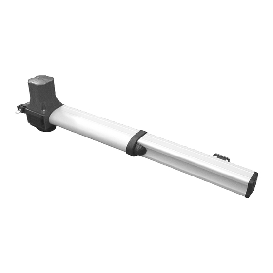
ALPHA International registered trademark n. 2.777.971 MECHANICAL INSTALLATION 1. FEATURES AND SPECIFICATIONS The ALPHA is provided with a mechanical locking system that grants the operator locking in the opened and closed position avoiding any needs for electric locks and/or magnetic locks. The torque intensity and the anti-crushing safety are adjustable through the control board. -
Page 7: Standard Installation
ALPHA International registered trademark n. 2.777.971 MECHANICAL INSTALLATION 2. TYPICAL INSTALLATION Fig 8 1) Operator 2) Warning notice inside 3) Electronic Unit 4) Tx Photocell 5) Rx Photocell 6) Key Switch 7) Radio Receiver Notice: 8) Antenna The operator must be installed with the motor facing 9) Column for photocells upward (Fig. -
Page 8: Gate Arrangement
ALPHA International registered trademark n. 2.777.971 MECHANICAL INSTALLATION 3. GATE ARRANGEMENT Fig. 10 It is necessary to make controls on the gate to make sure the application of ALPHA automation can be possible. Make sure that: A. the gate fixed and moving parts have a strong and crush-proof structure;... -
Page 9: Dimensions For Installation
ALPHA International registered trademark n. 2.777.971 MECHANICAL INSTALLATION DIMENSIONS FOR INSTALLATION Fig. 13 3,14 in (Alpha 330) 4,72 in (Alpha 550) (See Fig. 15) ALPHA 550 PLUS Fig. 14 Angolo di apertura 12,20 11,41 10,62 90° 8,66 9,44 10,23 10,23 120°... - Page 10 ALPHA International registered trademark n. 2.777.971 MECHANICAL INSTALLATION 4.3. Attach the operator on the previously installed back-bracket and fix it with the provided pivot (Fig 16) Fig. 16 4.4. Release the arm (see paragraph 3) 4.5. WARNING: Turn the shaft up to its max. extension, afterwards turn it about at least half turn into the opposit direction (screw it) see Fig. 17 and 18.
- Page 11 ALPHA International registered trademark n. 2.777.971 MECHANICAL INSTALLATION 4.8. Drill a hole into the gate (Fig 20) to be able to attach the front bracket with the supplied bolts being careful to place the operator perfectly horizontal (Fig 21). Fig. 20 Fig.
-
Page 12: Connections
ALPHA International registered trademark n. 2.777.971 MECHANICAL INSTALLATION ALPHA STANDARD 110V CONNEXIONS MOTOR Common CONTROL UNIT GROUNDING When inserting the lids (1) make sure that the Fig. 24 gaskets (2) are correctly installed. ALPHA PLUS 110V CONNEXIONS RIGHT LEFT Fig. 25 Fig. - Page 13 ALPHA International registered trademark n. 2.777.971 MECHANICAL INSTALLATION ALPHA 24V CONNEXIONS LIMIT SWITCH LIMIT SWITCH MOTOR OPENING CLOSING Fig. 27 Fig. 28 4.9. Release the arm (see paragraph 3) 4.10. Remove the pull tongue from the shaft-cover (Fig 29) and mount it on the operator through the two tie-rods without excessively tightening the two cover-nuts (Fig 30).
-
Page 14: Accessories
ALPHA International registered trademark n. 2.777.971 ALPHA ACCESSORIES KEY SWITCH EXTERNAL LOOP DETECTORS RADIO RECEIVER PHOTOCELLS SAFETY GATE MAGNETIC LOCK CARD TRANSMITTER FLASHING LAMP MAGNETIC LOCK BATTERY BACK-UP ELECTRIC LOCK 67410247 REV 03 - 05/2011... -
Page 15: Periodical Maintenance
ALPHA International registered trademark n. 2.777.971 PERIODICAL MAINTENANCE 1) Check the release function 2) Check the fixing pin 3) Check the integrity of the connection cables 4) Check the function and the limit switch condition in opening and closing 5) Clean the hinge of the leaf and lubricate it with recommended lubricant 6) Check for all corroded parts and replace them 7) Check the tight of the hardware of the gate 8) Check the operating of all accessories. -
Page 16: Releasing System Of The Operator
SEA recommend to the end user to release the operator only in case of power failure. Always contact the professional installer in case of not correct working of the operators. -
Page 17: Risk Examination
As for misunderstandings that may arise refer to your area distributor or call our help desk. These instructions are part of the device and must be kept in a well known place.The installer shall follow the provided intructions thoroughly. SEA USA Inc. products must only be used to automise doors, gates and lwings. Any initiative taken without SEA USA Inc. -
Page 18: Sales Conditions And Warranty
SEA. Recognized defects, whatever their nature, will not produce any responsibility and/or damage claims to SEA USA Inc and SEA s.r.l. Warranty shall not cover any required labor activities. Warranty will in no case be recognized if alterations and any other changes will be found on products. Warranty will not cover damages caused by carriers, expendable materials and faults due to improper use with the products specifications. - Page 20 International registered trademark n. 2.777.971 SEA USA Inc. 10850 N.W. 21st unit 160 DORAL MIAMI Florida (FL) 33172 Phone:++1-305.594.1151 Fax: ++1-305.594.7325 Toll Free: 800.689.4716 web site: www.sea-usa.com e-mail: sales@sea-usa.com...
Need help?
Do you have a question about the ALPHA Series and is the answer not in the manual?
Questions and answers