
Subscribe to Our Youtube Channel
Related Manuals for Parker MX80L


Summary of Contents for Parker MX80L
- Page 1 Manual No. : 100-5326-01 Rev: M Effective: June 10, 2021 Supersedes: March 6, 2020 MX80L Product Manual Automation...
-
Page 2: Important User Information
The information in the product manual, including any apparatus, methods, techniques, and concepts de- scribed herein, are the proprietary property of Parker Hannifin Corporation, Irwin Division or its licensors, and may not be copied, disclosed, or used for any purpose not expressly authorized by the owner thereof. -
Page 3: Table Of Contents
Encoder Specifications Hall Effect Specification Limit and Home Sensor Specifications Low ESD Specifications Standard Cabling and Wiring Diagrams Chapter 3 - How to Use the MX80L Mounting Orientations Mounting Surface Requirements Load Mounting Requirements Limit and Home sensor operation Adjusting the Limit Flag Procedure... -
Page 4: Revision Notes
MX80L Series Product Manual Revision Notes Revision 1 -Original Document Revision 2 – 8/25/03 Made numerous spelling corrections Added precision grade tables Page 9 – Modified configurable to include precision grade tables Page 13 – Modified specifications to include precision grade tables Page 25 –... -
Page 5: Chapter 1 - Introduction
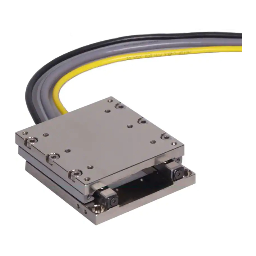
MX80L Positioner Although the MX80L is small in size and weight, it is large on performance and reliability. All key components are integral to the unit - residing within the body of the stage to provide a clean looking, reliable, unobstructed package. At the heart of the MX80L is an inno- vative non-contact linear servo motor (patent pending). -
Page 6: Return/Service Information
Vertical Operation The MX80L is NOT recommended for vertical operation unless it is configured with the pneumatic assist option. If the pneumatic assist is not used, the carriage and customer's load will fall in power loss situations potentially causing product or load damage or personal injury. -
Page 7: Specification Conditions
MX80L Series Product Manual Specification Conditions Specifications Are Temperature Dependent Catalog specifications are obtained and measured at 20 Degrees C. Specifications at any other temperature may deviate from catalog specifications. Minimum to maximum continuous operating temperature range (with NO guar- antee of any specification except motion) of a standard unit before failure is 5 - 40 degrees C. -
Page 8: Assembly Diagram
MX80L Series Product Manual Assembly Diagram Parker Hannifin Corporation Automation Irwin, Pennsylvania... -
Page 9: Chapter 2 - Mx80L Series Table Specifications
MX80L Series Product Manual Chapter 2 - MX80L Series Table Specifications Order Number Nomenclature ① ② ③ ④ ⑤ ⑥ ⑦ ⑧ ⑨ ⑩ ⑪ ⑫ ⑬ ⑭ Order Example: MX80L – CM05 ① Series ⑨ Z Channel Location MX80L... -
Page 10: Dimensional Drawings
MX80L Series Product Manual Dimensional Drawings Parker Hannifin Corporation Automation Irwin, Pennsylvania... - Page 11 MX80L Series Product Manual Z-axis configuration with counter balance (not available on 200mm Travel) 25 and 50mm travel MX80L-T01 or T02 5.6[0.22] 16.0[0.63] 100-9822-01 Qty (2) 002-2223-01 Cylinder assembly 125.0[4.92] 13.1[0.51] 45.0[1.77] Z axis shown at mid-travel position 100mm travel MX80L-T03 5.6[0.22]...
- Page 12 MX80L Series Product Manual 150mm travel MX80L-T04 5.7[0.22] 16.0[0.63] 002-2223-01 Cylinder assembly 285.0{11.22] 100-9822-02 Qty (2) 75.0[2.95] 7.1 [0.28] Z axis - shown at mid-travel Parker Hannifin Corporation Automation Irwin, Pennsylvania...
-
Page 13: General Table Specifications
MX80L Series Product Manual General Table Specifications MX80LP Precision Grade MX80LS Standard Grade Travel (mm) 8 (18) Normal Load Capacity kg (lb) 8 (18) 8 (18) 8 (18) 8 (18) 8 (18) 8 (18) 8 (18) 8 (18) Maximum Acceleration... -
Page 14: Test Methodology
Tests are performed with the table mounted to a granite table, unload- ed at 20 In this example, the accuracy of an MX80L-T02 ranges from -3.68 microns to 2.64 microns. This table and travel- would have its accuracy specified as 6.32 micron since the worst case would be starting at one extreme ing to the other. -
Page 15: Mx80L Series Technical Data
MX80L Series Product Manual MX80L Series Technical Data The useful life of a linear table at full catalog specifications is dependent on the forces acting upon it. These forces include both static components resulting from payload weight, and dynamic components due to acceleration/deceleration of the load. - Page 16 MX80L Series Product Manual [T01] Travel Moment Life-Load Charts Life - Moment Chart 25mm travel Pitch-Yaw Loading 100000 10000 1000 1 50 Load [kg] Life - Moment Chart 25mm travel Roll Loading 100000 10000 1000 Load [kg] Parker Hannifin Corporation...
- Page 17 MX80L Series Product Manual [T02] Travel Moment Life-Load Charts Life-Moment Chart 50mm travel Pitch-Yaw Loading 100000 10000 1000 Load [kg] Life-Moment Chart 50mm travel Roll Loading 100000 10000 1000 Load [kg] Parker Hannifin Corporation Automation Irwin, Pennsylvania...
- Page 18 MX80L Series Product Manual [T03] Travel Moment Life-Load Charts Life- Moment Chart 100mm travel Pitch-Yaw Loading 100000 10000 1000 Load [kg] Life - Moment Chart 100mm travel Roll Loading 100000 10000 1000 Load [kg] Parker Hannifin Corporation Automation Irwin, Pennsylvania...
- Page 19 MX80L Series Product Manual [T04] Travel Moment Life-Load Charts Life- Moment Chart 150mm travel Pitch-Yaw Loading 100000 10000 1000 Load [kg] Life- Moment Chart 150mm travel Roll Loading 100000 10000 1000 Load [kg] Parker Hannifin Corporation Automation Irwin, Pennsylvania...
- Page 20 Linear Motion Guide Bearing Life/Load Computation To predict the travel life of the MX80L cross roller bearings under a moment load use the curve with the correspond- ing lever arm and given load. Factor in dynamic as well as static loads. For compound loading (multiple moments) use an “effective lever arm of 2x actual lever arm.
- Page 21 Force/ Speed Chart The Force/Speed Charts for the MX80L are shown for all available travels. In the maximum allowable travel range the motor force is the same for 80 and 48 VDC bus voltage. See Electrical Specifications for motor parameters. Performance based on table mounted to 200mmx150mmx20mm Aluminum plate.
-
Page 22: Electrical Specifications
MX80L Series Product Manual Electrical Specifications Specifications for both the 4 pole and 8 pole linear servo motors 25 & 50 mm 100 mm 150 mm Parameter: Symbol: Units: Stall Force Continuous [1] Stall Current Continuous [1, 4, 8] Ics(sine) Amps Peak 1.13... -
Page 23: Clean Room Preparation
0.3 mm diameter and larger particles. Based on results from testing following the 209E Federal Standard, the following chart shows the expected clean room compatibility of the MX80L with Class 10 clean room prep. Consult factory for details on test methodology and results. -
Page 24: Encoder Specifications
MX80L Series Product Manual Encoder Specifications Description Specification Input Power 5 VDC +/-5% 150 to 220 mA depending on encoder resolution Output (Incremental) Square wave differential line driver (EIA RS422) 2 channels A and B in quadrature (90 ) phase shift. -
Page 25: Standard Cabling And Wiring Diagrams
MX80L Series Product Manual Standard Cabling and Wiring Diagrams Connector Pin Out and Extension Cable Wire Color Codes for the 5, 1, 0.5 and 0.1 micron resolution encoders Not included HD15M-VL - LIMITS with [H1][L1] HD15M-VF - FEEDBACK MOTOR HD15M-VL – LIMITS CONNECTOR HD15M-VF –... -
Page 26: Chapter 3 - How To Use The Mx80L
Z-BRACKET Mounting Surface Requirements Proper mounting of the MX80L is essential to optimize product performance. All specifications are based on the follow- ing conditions: • The positioner must be bolted down using all counter bored mounting holes provided (4 on T01 & T02, 8 on T03, T04, &... -
Page 27: Load Mounting Requirements
M4 with 7mm of engagement as to not damage the table. Use appropriate length bolt. The MX80L compact design requires proper sized bolts to be used when mounting payloads to the carriage. Excessive length bolts can damage bearings or pin the table in position. -
Page 28: Limit And Home Sensor Operation
The MX80L utilizes an innovative method for setting limit and home positions. The magnetic sensors embedded in the base of the MX80L change state based on the limit “flag”. This space saving, compact design consists of three (3) parts; magnetic sensors, limit flag and limit flag bracket. -
Page 29: Adjusting The Limit Flag Procedure
Step 1: Remove power from the unit and allow time for stage base and carriage to reach room temperature Step 2: Remove the limit flag bracket from the MX80L by re- moving the button head cap screws (BHCS) that secure the bracket to the side of the carriage. -
Page 30: Setting Home Sensor
Z Channel Position Reference The Z channel is an output on the encoder. Many servo controllers support this input. The Z channel on the MX80L is at mid travel. The Z channel is a unidirectional device. This means that the final homing direction must occur in one direction. -
Page 31: Grounding / Shielding
Cabling The MX80L is provided with high flex cabling which is strain relieved at the connection point on the positioner. The Hall/ Encoder cable is terminated with a high density 15 pin D-sub connector, HD15M-VF which is compatible with IPA, Vix and Aries drives. -
Page 32: Pneumatic Counterbalance
MX80L Series Product Manual Pneumatic Counterbalance Cylinder Specification Description Specifications Cylinder Piston Area 0.105 in Cylinder Mounting Torque Head nut 0.45 – 0.90 Nm (4 – 8 in-lbs) Rod End. 0.23 – 0.56 Nm (2 – 5 in-lbs) Maximum Compressive Rod Force... -
Page 33: Chapter 4 - Performance
Travel Length The short travel length of the MX80L is the main limiting factor for maximum speed. The T01 and T02 options (25mm and 50mm) a triangular motion profile with 5g accel/decel will only yield peak speeds of 1.1m/sec and 1.5 m/s respectively. -
Page 34: Thermal Effects On Accuracy
(0.000022mm/mm/° C)*150mm*5 C. However, this additional error can be compensated for since the error is linear. The accuracy of the MX80L is plotted with respect to carriage temperature in the graph below for the 25 mm, 50 mm, 100 mm and 150 mm travel lengths. -
Page 35: Causes Of Temperature Increases
Motor heating from MX80L Since the MX80L uses a servo motor as its drive, it produces no heat unless there is motion, or a force being gen- erated. In low duty cycle applications heat generation is low, however as duty cycles increase, temperature of the MX80L will increase, causing thermal expansion of the base. -
Page 36: Chapter 5 - Connecting To Drives
MX80L Series Product Manual Chapter 5 - Connecting to Drives Compax3 Cabling and Wiring Diagrams Compax3 Connector Pin Out and Extension Cable Wire Color Codes HD15M-CL - LIMITS HD15M-CF12 - FEEDBACK MOTOR HD15M-CF12 – FEEDBACK-HALL CONNECTOR FUNCTION WIRE COLOR Sense- WHITE/GREEN HD15M-CL –... -
Page 37: Vix Cabling And Wiring Diagrams
Limits use Inputs The ViX drive has 5 digital inputs. When using with MX80L, the EOT Limits and Home use 3 of the 5 inputs. A VM15-PF screw terminal breakout board may be purchased to allow access to the remaining 2 inputs and all of the outputs. -
Page 38: Chapter 6 - Maintenance And Lubrication
MX80L Series Product Manual Chapter 6 - Maintenance and Lubrication Cross Roller Bearing Lubrication Standard Prep: • Recommended Lubricant: Mobil Vactra No. 2, oil • Lubrication Interval: 1000 hours* • Method: Lightly coat the bearing surfaces with oil. Bearings surfaces can be exposed by moving the table to the end of trav- el lubricating the now exposed surfaces, then moving the table to the other end of travel and lubricating the other set of surfaces. -
Page 39: Appendix A - Internal Protection
MX80L Series Product Manual Appendix A - Internal Protection Parker has conducted testing to determine the degree to which the positioner is protected by using a British standard called an Ingress Protection Rating (IP Rating). The MX80L has an IP 10 protection rating. -
Page 40: Appendix B - Ce Declaration Of Conformity
MX80L Series Product Manual Appendix B - EC Declaration of Conformity Parker Hannifin Corporation Automation Irwin, Pennsylvania...
Need help?
Do you have a question about the MX80L and is the answer not in the manual?
Questions and answers