Sign In
Upload
Download
Table of Contents
Contents
Add to my manuals
Delete from my manuals
Share
URL of this page:
HTML Link:
Bookmark this page
Add
Manual will be automatically added to "My Manuals"
Print this page
×
Bookmark added
×
Added to my manuals
Manuals
Brands
Parker Manuals
Valve Positioners
LCR Series
Product manual
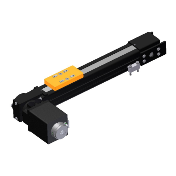
Parker LCR Series Product Manual
Light capacity rodless miniature linear positioners
Hide thumbs
1
2
Table Of Contents
3
4
5
6
7
8
9
10
11
12
13
14
15
16
17
18
19
20
21
22
23
24
25
26
27
28
29
30
31
32
33
34
35
36
37
38
39
page
of
39
Go
/
39
Contents
Table of Contents
Bookmarks
Table of Contents
Table of Contents
Chapter 1 Introduction
Product Description
Unpacking
Warranty Repair
Warnings Precautions
Specification Conditions
Chapter 2 LCR Specifications
Configurable Part Number
LCR22 Screw Drive Dimensional Drawing
LCR30 Belt Drive Dimensional Drawing
LCR22 Screw Drive Dimensional Drawing
LCR30 Belt Drive Dimensional Drawing
LCR22 Idler Dimensional Drawing
LCR30 Idler Dimensional Drawing
LCR22 Screw Drive Performance Specifications
LCR30 Screw Drive Performance Specifications
LCR22 Belt Drive Performance Specifications
LCR30 Belt Drive Performance Specifications
Chapter 3 Component Specifications
Motor Specifications
Stepper Motor Encoder Specifications
Limit Home Switch Specifications
LCR22 Screw Drive Reflected Inertias
LCR22 Maximum Allowable Speeds
LCR30 Screw Drive Reflected Inertias
LCR30 Screw Drive Maximum Allowable Speeds
Chapter 4 Set up and Usage
Base Mounting
Coupling Installation Screw Drives
Payload Mounting
Moment Load Pre-Cautions
Limit/Home Adjustment
Chapter 5 Maintenance and Repair
Lubrication
LCR22 Belt Drive Motor Mounting
LCR30 Belt Drive Motor Mounting
LCR Belt Drive Tensioning
Strip Seal Replacement
Accessories & Spare Parts List
Chapter 6 Compliance Documents
Advertisement
Quick Links
Download this manual
MANUAL NO. 102-4109-01
REV E
EFFECTIVE
: May 18, 2018
SUPERCEDES : July 11, 2014
Table of
Contents
Previous
Page
Next
Page
1
2
3
4
5
Advertisement
Table of Contents
Need help?
Do you have a question about the LCR Series and is the answer not in the manual?
Ask a question
Questions and answers
Related Manuals for Parker LCR Series
Valve Positioners Parker LCR30 Product Manual
Light capacity rodless miniature linear positioners (39 pages)
Valve Positioners Parker 406LXR Series Product Manual
Electromechanical positioning systems (68 pages)
Valve Positioners Parker 404 Product Manual
Electromechanical positioning systems (47 pages)
Valve Positioners Parker Daedal 412T01LXR Product Manual
Electromechanical positioning systems (47 pages)
Valve Positioners Parker HMR Series Assembly And Operating Instructions Manual
(49 pages)
Valve Positioners Parker 404LXR Series Product Manual
Electromechanical positioning systems (48 pages)
Valve Positioners Parker MX80L Product Manual
(40 pages)
Valve Positioners Parker MSR Series User's Information Manual
(23 pages)
Valve Positioners Parker 412LXR Series Product Manual
Electromechanical positioning systems (45 pages)
Valve Positioners Parker Daedal 400LXR Series Product Manual
Electromechanical positioning systems (47 pages)
Valve Positioners Parker 404XE Series Product Manual
Electromechanical positioning systems (35 pages)
Valve Positioners Parker MX80L series Product Manual
Electromechanical positioning systems. precision grade and standard grade (44 pages)
Valve Positioners Parker 401XE Series Product Manual
Electromechanical positioning systems (37 pages)
Valve Positioners Parker MX80S Series Product Manual
Electromechanical positioning systems (36 pages)
Valve Positioners Parker 401XR Series Product Manual
Electromechanical positioning systems (31 pages)
This manual is also suitable for:
Lcr22
Lcr30
Lcr22 series
Lcr30 series
Table of Contents
Print
Rename the bookmark
Delete bookmark?
Delete from my manuals?
Login
Sign In
OR
Sign in with Facebook
Sign in with Google
Upload manual
Upload from disk
Upload from URL


Need help?
Do you have a question about the LCR Series and is the answer not in the manual?
Questions and answers