
Related Manuals for Parker HMR Series


Summary of Contents for Parker HMR Series
- Page 1 MANUAL NO. 109-0523-01 REV F EFFECTIVE: August 3, 2020 SUPERCEDES: December 13, 2018 HMR Series Positioners Assembly and Operating Instructions...
- Page 2 Parker-Hannifin shall not be held liable, regardless of any legal basis, except for cases of intent or gross negligence; injuries to life, body or health; or defects of malicious nondisclosure or whose absence was expressly guaranteed in writing.
- Page 3 HMR Series Positioners Revision Notes Revision—8/15/15 Original Document Revision A - 9/23/2015 Revised graphs with updated information Revision B– 12/2/15 Fixed chart on pg 15 with correct MP values, added revision page (renumbered) Revision C– 8/31/17 Added not that limit/ home choice is restricted with short travel options p 53, 55 Revision D–...
-
Page 4: Table Of Contents
HMR Series Positioners Page Contents Foreword to the Operating Instructions Safety Product Information Scope of Application Type Plate Application, Proper Use Prerequisite for Product Usage Conversions and Modifications Spare Parts and Accessories Transportation and Storage Transportation Storage Brief Description and Function... -
Page 5: Foreword To The Operating Instructions
Operators Operators for the overall system must ensure that the HMR is only operated by authorized and qualified personnel. Authorized personnel include trained specialists from the operator, from the manufacturer (Parker-Hannifin ) and from an approved service partner. Working in a safety-conscious manner Check at reasonable intervals that personnel are working in a safety-conscious manner and adhering to the operating instructions. -
Page 6: Product Information
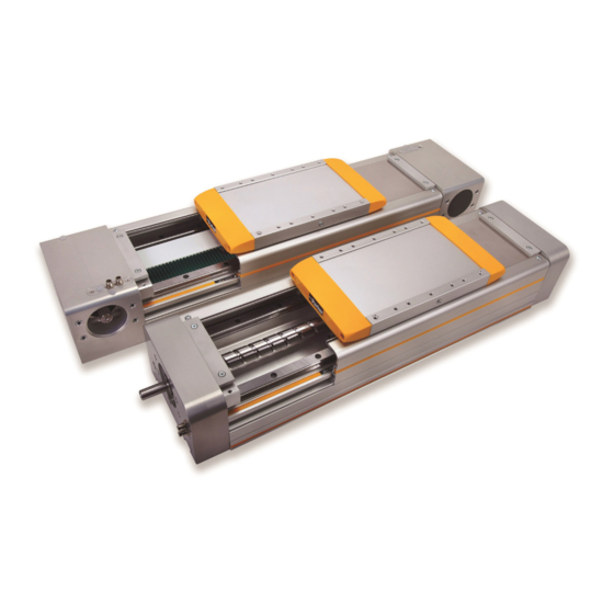
HMR Series Positioners Product Information Ball screw drive Belt drive Scope of Application The description in these operating instructions relates to the products. 3.1.1 Ball Screw Drive Linear drive with ball screw drive and dual ball bearing rail guides. HMRS08... -
Page 7: Application, Proper Use
Conversions and Modifications HMR linear drives may not be modified with respect to the design or safety-related features without the written approval of Parker-Hannifin . Any unauthorized modification in this respect will exclude any liability on the part of Parker-Hannifin . -
Page 8: Transportation And Storage
• Larger deformations could result in a reduced service life, increased wear, and increased friction. These must therefore be avoided! • Attach ropes as shown/use fork as shown. NOTE Notify the shipping company and Parker-Hannifin or the delivery company immediately, in writing, of any transportation damage or missing parts. Storage The storage location must be: •... -
Page 9: Brief Description And Function
• Load-carrying capacity, forces and torques • Weights and further technical data The electric linear drives from the HMR series may only be operated within the permissible specifications. We reserve the right to make technical changes. Setup and Mode of Action The electric HMR linear drives are used for the linear moving and positioning of an external payload. - Page 10 HMR Series Positioners 6.3.1 HMRS Ball Screw Drive A carriage is linearly moved by a rotating ball screw drive driven by the motor; the carriage is mounted on a guide system in a movable manner. The screw turns clockwise. The load to be moved is fastened onto the carriage.
- Page 11 HMR Series Positioners 6.3.2 HMRB Belt Drive A carriage is linearly moved by a toothed belt driven by the motor; the carriage is mounted on a guide system in a movable manner. The load to be moved is fastened onto the carriage.
-
Page 12: Profile Versions
Ball bearing guide Runner blocks with balls are moved linearly on a precision guide rail made of steel. The maintenance schedule recommended by Parker Hannifin in section 9 must be followed. Carriage The carriage moves an externally connected load in a linear fashion. The external load may only be fastened at the pre-existing threaded holes. -
Page 13: Assembly
Maximum permissible loads must not be exceeded. The sum of all loads must under no circumstance be > 1. Take note of the additional information in the Parker HMR catalog on the “Maximum permissible load”. Electrical information The controller, motor, position detection and all other necessary electrical elements must be connected according to technical rules, within the responsibility of the operator. -
Page 14: Installation Of Linear Drive
HMR Series Positioners Installation of Linear Drive All installation measurements can be found under “6.3 Carrier profile and drive body” and in the HMR catalog. During assembly, the HMR must be sufficiently supported and securely placed in a machine/system. ATTENTION... - Page 15 HMR Series Positioners 7.2.2 Mounting with T-slot fixture Use of the side T-slot profile. Screwing direction downwards. Clamps can be supplied as accessories, see Parker HMR catalog. NOTE Adhere to the tightening torques for screws according to section 7.1. Please observe the required number of T-sliding blocks in accordance with the axial holding force for secure assembly (see...
- Page 16 HMR Series Positioners 7.2.3 Distance between supports WWW.PARKERMOTION.COM PH: (724)-861-8200...
-
Page 17: Attaching The Payload
HMR Series Positioners Attaching the Payload The user is responsible for the use of the HMR and makes decisions on the attachment of loads as well as the operating status with speed, acceleration and frequency of movements. The HMR may only be installed according to the catalog’s specifications. -
Page 18: Cover For Ip54
HMR Series Positioners Cover for IP54 It is also possible to install various assemblies and equipment as a retrofit. When doing so, remove the cover as necessary. HMRS Clamping plate Top Cover Carriage End Cap Outer band Deflector Rubber Side Scraper... - Page 19 HMR Series Positioners For HMR installation, maintenance purposes or conversion: 7.4.1 IP54 Cover Disassembly Cord Top Cover Carriage End Cap Clamping Plate Outer band HMRB • Remove the clamping plate of the outer band on the end caps. • Disassemble the carriage top cover. Note that if only replacing outer band, do not remove top cover—remove end caps only.
- Page 20 HMR Series Positioners 7.4.2 IP54 Cover Assembly The cover can be retrofitted; refer to section 11.1. The following instructions also apply to retrofitting, converting or maintaining the HMR. For information on necessary disassembly, refer to section 7.4.1. ATTENTION It is possible to implement an incorrect assembly sequence.
-
Page 21: 7.4.3 Outer Band Install
HMR Series Positioners 7.4.3 Outer Band Install Outer band Clamping Plate Side Scraper Support Clamp Cover Cord HMRB Attention Premature wear of the outer band Careful tightening of the clamping strip - Outer band not twisted - Install without forming any ripples. - Page 22 HMR Series Positioners • Insert side scrapers into the grooves on the carriage - lips should face outward. • Wrap black cord around carriage and tie. Cord to be trimmed at the end of outer band install. • Place support clamps in cover holders with cushion tape facing upwards and towards the carriage.
-
Page 23: Position Detection With Magnetic Switches
HMR Series Positioners Position Detection with Magnetic Switches ATTENTION Potential damage to equipment! Missing or incorrect signals from the end position switches in the controller Essentially, clamp and set up end switches before commissioning 7.5.1 Definition End position switch The use of end position switches is highly recommended for operating electric linear drives to prevent mechanical damage in the end positions. - Page 24 HMR Series Positioners 7.5.2 Magnetic Switch Types Electrical connection: Electrical connection: Electrical connection: Cable type RST-K Cable type EST-K Plug type RST-S Reed 2-pole PNP 3-pole Reed 2-pole Type EST-S PNP 3-pole 7.5.3 Connection Assignment for M8 Connector The connector assignment complies with DIN EN 50044 3-pin connector assignment 7.5.4...
-
Page 25: Impact Protection
HMR Series Positioners 7.5.5 Setting up and replacement of internal magnetic switches For service on internal magnetic switches, please contact the factory for support. Impact Protection Impact protection reduces the risk of mechanical damage from an unbraked, unforeseeable impact in the end position. -
Page 26: Motor And Gearbox Mounting
HMR Series Positioners Motor and Gearbox Mounting Overview / exploded view of motor installation with a flange plate, using a toothed belt as an example. Motor coupling Motor Drive shaft Coupling housing Motor flange Overview / exploded view of gearbox installation with two flange plates, using a spindle drive as an example. - Page 27 Parker-Hannifin or the operator. EL-sizing, the software-based design program from Parker-Hannifin, also provides reliable combinations of linear drive and drive system. The maximum torque on the drive shaft of the linear drive must not be exceeded at any time.
- Page 28 HMR Series Positioners 7.7.3 Drive System Installation NOTE When installed, both parts of the motor coupling must have a defined gap dimension “Y”. Also note the clearance dimensions in the following table in relation to the shaft of the motor or gearbox used.
- Page 29 HMR Series Positioners • Mount the motor coupling with clearance “Z” to Gearbox Motor Coupling the motor shaft or gearbox shaft WARNING Shaft breakage due to Non-Alignment Severe injuries and damage to property caused by unbraked payload. Centering of drive shaft and motor shaft / gearbox shaft via coupling housing and flange.
-
Page 30: Commissioning
HMR Series Positioners Commissioning The HMR linear drive can generate quick linear movements with great force. This can result in injuries due to crushing of body parts or damage caused by collision with other system parts if the safety regulations are not observed. -
Page 31: Maintenance And Repair
HMR Series Positioners Maintenance and Repair Customer Service To obtain the address for spare parts and customer service, see the back of these operating instructions. General Cleaning Maintenance and repair work may only be carried out by trained personnel Caution... -
Page 32: Checking The Play Of The Guide System
HMR Series Positioners Checking the Play of the Guide System Horizontal and vertical play can occur after a certain number of operating hours and service time. Checks for play should only be evaluated and conducted by trained mechanical technicians. NOTE With the ball bearing guide, no play must be discernible when the carriage is rotated by hand. - Page 33 HMR Series Positioners 9.7.1 Check belt tensioning The most certain results measuring belt tensioning can be adjusted and reviewed in practice by an experienced specialist. However, the toothed belt tension is measured and adjusted most reliably by using a belt tension measuring device. One method is to adjust using the frequency meter.
- Page 34 HMR Series Positioners 9.7.2 Testing the toothed belt tension with a force/displacement measuring device Please direct any queries on the force/displacement measuring device to Parker, ID no. 037-000202. Measurement process: • For vertical alignment of the drive, first dismantle the payload.
-
Page 35: Disassembling Of Belt Drive
HMR Series Positioners Disassembly of Drive Type Belt If present, the IP54 cover must be removed as per section 7.4.1 . The belt tensioning block needs to be removed on both sides. Following the procedure is described for one side. -
Page 36: Installing Belt Drive
HMR Series Positioners Belt clamping assembly Belt • Remove the screws of the belt clamping assembly and lay out the belt. • Repeat this with the other belt tensioning block. Cover End cap drive end Cover • Remove cover from the end cap drive end and end cap non drive end side. -
Page 37: 9.10 Drive Shaft Installation For Belt Units
HMR Series Positioners 9.10 Drive Shaft Installation for Belt Units • Disassemble belt from instructions in previous section 9.10.3 Disassembling of Drive Belt. Snap Ring • Remove snap rings from each side of shaft. • Remove old drive shaft and replace. Insert new snap rings into grooves inside end block housing. -
Page 38: Decommissioning
HMR Series Positioners Decommissioning 10.1 Disassembly of a Machine or System Disassembly and the final decommissioning of the HMR must be carried out by trained mechanical or electrical specialists. No stored energy (springs, fluid, pressure). Caution Crushing hazard due to unexpected movements This could result in sever injuries or damage to property Bring system to a standstill and secure. -
Page 39: Retrofit Kits
HMR Series Positioners Retrofit Kits 11.1 IP54 Cover If the cover is to be completely retrofitted, the product key must be indicated. Example: HMRS15C050-1250-00000K1AF Frame Size **Carriage type includes 0 = Standard (One Carriage) Carriage Type** 1 = Tandem (Two Carriages) -
Page 40: Spare Part / Wearing Part Kits
HMR Series Positioners Spare Part / Wearing Part Kits 12.1 Outer Band Package If the outer band package needs to be replaced, the product key must be indicated. Example: HMRS15C050-1250-00000K1AF Frame Size **Carriage type includes 0 = Standard (One Carriage) -
Page 41: Belt
HMR Series Positioners 12.3 Belt If the belt is to be replaced, the product key must be indicated. Example: HMRB15CBD 0-1250-00000K1AF Frame Size * Drive Shaft Options **Carriage type includes Drive Shaft* BD/DD =Front/Back 0 = Standard (One Carriage) Carriage Type**... -
Page 42: Belt Pulleys
HMR Series Positioners 12.4 Drive Shafts Belt * Drive Shaft Options BD - 090 degree front with double plain shaft If the belt is to be replaced, the product key must be indicated. DD - 270 degree back with double plain shaft... -
Page 43: Impact Protection
HMR Series Positioners 12.5 Impact protection If the impact protection is to be replaced, the product key must be indicated. Example: HMRS15C100-1200-000000000 Example: HMRB15CBD0-1200-000000000 To ensure that a suitable impact protection can be delivered, the following must be known at the very least: •... -
Page 44: Compliance Documentation
HMR Series Positioners Compliance Documentation DECLARATION OF INCORPORATION ACCORDING TO EC DIRECTIVE 2006/42/EC (ANNEX II, PART 1,SECTION B) FOR PARTLY COMPLETED MACHINERIES EN ISO 12100 Safety of Applications Plant and Machinery EN/IEC 60204-1 Safety of machinery - Electrical equipment of machines - Part 1: general requirements WWW.PARKERMOTION.COM... -
Page 45: Configurable Order Number
HMR Series Positioners Configurable Order Number 14.1 HMRS HMRS Order Code: ① ② ③ ④ ⑤ ⑥ ⑦ ⑧ ⑨ ⑩ ⑪ ⑫ ⑬ ⑭ - 0250 - ① HMR ② Type of Actuator Ball Screw Drive ③ Frame Size... - Page 46 HMR Series Positioners ⑬ Mounted Gearhead Mounted Gearhead (with flange and coupling for motor as selected in position 14) No Gearhead Mounted H1 PS115-003-S2- 3:1 PV60TA-010 10:1 PS60-003-S2- 3:1 H2 PS115-005-S2- 5:1 PV90TA-003 3:1 PS60-005-S2- 5:1 H3 PS115-010-S2- 10:1 PV90TA-005 5:1...
-
Page 47: Hmrb
HMR Series Positioners 14.2 HMRB HMRB Order Code: ① ② ③ ④ ⑤ ⑥ ⑦ ⑧ ⑨ ⑩ ⑪ ⑫ ⑬ ⑭ 1 - 0250 - ① ② Type of Actuator B Timing Belt Drive ③ Frame Size Profile Width- 085mm... - Page 48 HMR Series Positioners ⑪ Place Holder ⑫ Place Holder ⑬ Mounted Gearhead Mounted Gearhead (with flange and coupling for motor as selected in position 14) No Gearhead Mounted H1 PS115-003-S2- 3:1 PV60TA-010 10:1 PS60-003-S2- 3:1 H2 PS115-005-S2- 5:1 PV90TA-003 3:1...
- Page 49 HMR Series Positioners Parker Hannifin Corporation Electromechanical Automation Div. 1140 Sandy Hill Road Irwin, PA 15642 1-800-245-6903 WWW.PARKERMOTION.COM PH: (724)-861-8200...
Need help?
Do you have a question about the HMR Series and is the answer not in the manual?
Questions and answers