Fortinet FortiGate-7000E Series System Manual
Hide thumbs
Also See for FortiGate-7000E Series:
- System manual (61 pages) ,
- Manual (29 pages) ,
- Manual (31 pages)
Table of Contents
Advertisement
Quick Links
Advertisement
Table of Contents

Related Manuals for Fortinet FortiGate-7000E Series


Summary of Contents for Fortinet FortiGate-7000E Series
- Page 1 FortiGate-7060E System Guide FortiGate-7000E Series...
-
Page 2: Connecting To The Fortios Cli Of The Fim In Slot
FORTINET DOCUMENT LIBRARY https://docs.fortinet.com FORTINET VIDEO GUIDE https://video.fortinet.com FORTINET BLOG https://blog.fortinet.com CUSTOMER SERVICE & SUPPORT https://support.fortinet.com FORTINET TRAINING & CERTIFICATION PROGRAM https://www.fortinet.com/support-and-training/training.html NSE INSTITUTE https://training.fortinet.com FORTIGUARD CENTER https://fortiguard.com/ END USER LICENSE AGREEMENT https://www.fortinet.com/doc/legal/EULA.pdf FEEDBACK techdoc@fortinet.com Email: January 4, 2021 FortiGate-7060E 6.4.2 System Guide... -
Page 3: Table Of Contents
Mounting the FortiGate-7060E chassis in a four-post rack Mounting the FortiGate-7060E chassis in a two-post rack Cooling air flow and required minimum air flow clearance Inserting FIMs and FPMs Recommended slot locations for FIMs Getting started with FortiGate-7000 Multi VDOM mode FortiGate-7060E System Guide Fortinet Technologies Inc. - Page 4 Fortinet Technologies Inc. Confirming startup status Setting up management connections Setting up a single management connection Setting up redundant management connections Adding a password to the admin administrator account Changing data interface network settings Resetting to factory defaults Restarting the FortiGate-7060E...
- Page 5 Fortinet Technologies Inc. Industry Canada Equipment Standard for Digital Equipment (ICES) – Canada European Conformity (CE) - EU Voluntary Control Council for Interference (VCCI) – Japan Product Safety Electrical Appliance & Material (PSE) – Japan Bureau of Standards Metrology and Inspection (BSMI) – Taiwan...
-
Page 6: Change Log
Added DC terminal rings and information about included DC cables. See Optional accessories and replacement parts on page 14 DC PSUs and supplying DC power to the chassis on page October 29, 2019 Misc changes throughout. October 16, 2019 Restructuring and bug fixing. FortiGate-7060E 6.4.2 System Guide Fortinet Technologies Inc. -
Page 7: Fortigate-7060E Chassis
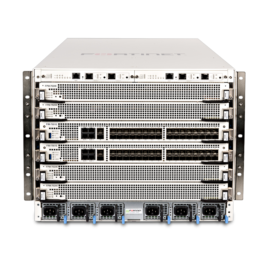
The FortiGate-7060E is a 8U 19-inch rackmount 6-slot chassis with a 80Gbps fabric and 1Gbps base backplane designed by Fortinet. The fabric backplane provides network data communication and the base backplane provides management and synch communication among the chassis slots. -
Page 8: Fim Modules
FortiGate-7060E chassis Fortinet Technologies Inc. Do not operate the FortiGate-7060E chassis with open slots on the front or back panel. For optimum cooling performance and safety, each chassis front panel slot must contain an FIM or FPM or an FIM or FPM blank panel (also called a dummy card). In addition, all cooling fan trays, power supplies or power supply slot covers must be installed while the chassis is operating. -
Page 9: Fpm-7630E
FortiGate-7060E chassis Fortinet Technologies Inc. FPM-7630E The FPM-7630E is a hot swappable processor module that provides FortiOS firewalling and security services. FPMs in the chassis function as workers, processing sessions load balanced to them by the FIMs. FPMs include multiple NP6 network processors and CP9 content processors to accelerate traffic. -
Page 10: Power Consumption For Different Fortigate-7060E Configurations
FortiGate-7060E chassis Fortinet Technologies Inc. FortiGate-7060E back panel Fan Tray 3 Fan Tray 2 Fan Tray 1 Chassis Ground Connector Power consumption for different FortiGate-7060E configurations The tables in this section provide information about how to calculate average and maximum power consumption for a FortiGate-7060E system with four and with two FPMs two FIM-7901Es. -
Page 11: Power Consumption Calculation With Four Fpm-7620Es
FortiGate-7060E chassis Fortinet Technologies Inc. Power consumption calculation with four FPM-7620Es Module Average power Max power Number of Total Max power consumption (W) consumption (W) modules average power (W) FPM-7620E 1280 1640 FIM-7901E Fan trays and SMMs Totals 2330 3277... -
Page 12: Power Consumption Calculation With Two Fpm-7630Es
FortiGate-7000 series products are registered according to the chassis serial number. You need to register your chassis to receive Fortinet customer services such as product updates and customer support. You must also register your product for FortiGuard services. Register your product by visiting https://support.fortinet.com... -
Page 13: Chassis Hardware Information
FortiGate-7060E chassis Fortinet Technologies Inc. MGMT1 (inactive by default, IPMB 0x22) MGMT2 (active by default, IPMB 0x20) IPMB SMC SDI SMC SDI SERIAL FPM5 IPMB 0x8A IPMB NP6 CP9 SERIAL SMC SDI FPM3 IPMB 0x86 IPMB NP6 CP9 SERIAL SMC SDI... -
Page 14: Shipping Components
FortiGate-7060E chassis Fortinet Technologies Inc. Shipping components The FortiGate-7060E chassis ships pre-assembled with the following components: The 8U FortiGate-7060E chassis. Two FIM modules. Up to four FPM modules. Two System Management Modules (SMMs) in the front of the chassis. (SMMs are not field replacable. If a SMM fails, you must RMA the chassis. -
Page 15: Physical Description Of The Fortigate-7060E Chassis
FortiGate-7060E chassis Fortinet Technologies Inc. The following optional accessories can be ordered separately: Additional FIM and FPM modules Transceivers DC PSUs Additional AC PSUs Additional FAN trays Air Filter kit FPM and FIM blank panels to be installed in empty chassis slots Physical description of the FortiGate-7060E chassis The FortiGate-7060E chassis is a 8U chassis that can be installed in a standard 19-inch rack. -
Page 16: Cooling Fans, Cooling Air Flow, And Minimum Clearance
FortiGate-7060E chassis Fortinet Technologies Inc. Cooling fans, cooling air flow, and minimum clearance The FortiGate-7060E chassis contains three hot swappable cooling fan trays installed in the back of the chassis. Each fan tray includes two fans that operate together. When the fan tray LED is green, both fans are operating normally. If the LED turns red or goes off, one or both of the fans is not working and the fan tray should be replaced. -
Page 17: Cooling Air Flow And Required Minimum Air Flow Clearance
FortiGate-7060E chassis Fortinet Technologies Inc. Cooling Fan Tray Retention Retention Screw Screw Outlet Grill Outlet Grill Retention Retention Screw Screw Cooling air flow and required minimum air flow clearance . The following diagram When installing the chassis, make sure there is enough clearance for effective cooling air flow shows the cooling air flow through the chassis and the locations of fan trays. -
Page 18: Optional Air Filter
FortiGate-7060E chassis Fortinet Technologies Inc. FortiGate-7060E cooling air flow and minimum air flow clearance Back Front FortiGate-7060E chassis (side View) 100 mm 100 mm Trays Left and Right Side Cool Air Cool air Intakes Warm Air Intake 50 mm Exhaust... -
Page 19: Hot Swapping An Ac Psu
FortiGate-7060E chassis Fortinet Technologies Inc. Use a C15 Power cable, supplied with the chassis, to connect power to each PSU C16 power connector. C15/C16 power connectors are used for high temperature environments and are rated up to 120°C. AC PSU showing C16 power connector... - Page 20 FortiGate-7060E chassis Fortinet Technologies Inc. FortiGate-7060E front panel on page 7 for locations of the PSUs. The diagram shows AC PSUs, with a DC version of the chassis the AC PSUs are replaced with DC PSUs. Each PSU is designed to be installed in a Telecom data center or similar location that has available -48VDC power fed from a listed 40A circuit breaker.
-
Page 21: Crimping Guidelines
FortiGate-7060E chassis Fortinet Technologies Inc. State Description voltage outside of normal operating range. Flashing Amber Warning that power input or output is close to outside of normal operating range. PSU should be replaced. Crimping guidelines To connect the PSUs to data center power you should use 8 AWG or larger wires depending on the wire length and the power requirements of your chassis. -
Page 22: Hot Swapping A Dc Psu
FortiGate-7060E chassis Fortinet Technologies Inc. One red 8 AWG stranded wire with attached UL approved ring terminal for 8/M4 studs with ext ring diameter < 9.8 To connect a PSU to DC power 1. Attach the ESD wrist strap to your wrist and to an ESD socket or to a bare metal surface on the chassis or frame. -
Page 23: Connecting The Fortigate-7060E Chassis To Ground
FortiGate-7060E chassis Fortinet Technologies Inc. Connecting the FortiGate-7060E chassis to ground The FortiGate-7060E chassis includes a ground terminal on the rear the bottom of the FortiGate-7060E back panel. The ground terminal provides two connectors to be used with a double-holed lug such as Thomas & Betts PN 54850BE. This connector must be connected to a local ground connection. -
Page 24: Fortigate-7060E Hardware Assembly And Rack Mounting
The front mounting brackets are not required to mount the FortiGate-7060E in a two-post rack (see Mounting the FortiGate-7060E chassis in a two-post rack on page 27). FortiGate-7060E 6.4.2 System Guide Fortinet Technologies Inc. -
Page 25: Left And Right Cable Management Brackets
(FIM-7910E/FIM-7920E only) Front cable management brackets (FIM-7910E and FIM-7920E only) These front cable management brackets are not included with the FortiGate-7060E package. Fortinet ships a front cable management bracket with each FIM-7910E and FIM-7920E module. These brackets help support the relatively large CFP2 transceivers used with FIM-7910E modules and QSFP28 transceivers used with FIM-7920E modules. -
Page 26: Power Cord Clamps
FortiGate-7060E hardware assembly and rack mounting Fortinet Technologies Inc. Power cord clamps You can also install power cord clamps into the back of the chassis beside each PSU. Install the clamps by inserting them into the holes adjacent each supply at the back of the chassis. Use the clamps to secure the AC power cords so they are not accidentally disconnected. -
Page 27: Mounting The Fortigate-7060E Chassis In A Two-Post Rack
FortiGate-7060E hardware assembly and rack mounting Fortinet Technologies Inc. Mounting the FortiGate-7060E chassis in a two-post rack The FortiGate-7060E package includes two mid-mount trays and two mid-mount ears that you can use to mount the chassis in a 2-post rack. As shown in the diagram, first attach the mid-mount trays to the rack making sure to leave enough space above the trays for the chassis. -
Page 28: Inserting Fims And Fpms
FortiGate-7060E hardware assembly and rack mounting Fortinet Technologies Inc. FortiGate-7060E cooling air flow and minimum air flow clearance FortiGate-7121F chassis (side View) Front Back 100 mm 100 mm Trays Cool air Warm Air Intake Exhaust Trays 675 mm Cool air enters the chassis through the chassis front panel and warm air exhausts out the back. For optimal cooling, allow 100 mm of clearance at the front and back of the chassis. -
Page 29: Recommended Slot Locations For Fims
FortiGate-7060E hardware assembly and rack mounting Fortinet Technologies Inc. Do not operate the FortiGate-7060E chassis with open slots on the front or back panel. For optimum cooling performance and safety, each chassis front panel slot must contain an FIM or FPM or an FIM or FPM blank panel (also called a dummy card). In addition, all cooling fan trays, power supplies or power supply slot covers must be installed while the chassis is operating. - Page 30 FortiGate-7060E hardware assembly and rack mounting Fortinet Technologies Inc. if your chassis includes a FIM-7901E and a FIM-7904E, install the FIM-7901E in chassis slot 1 and the FIM-7904E in chassis slot 2. If your chassis includes a FIM-7904E and a FIM-7920E, install the FIM-7904E in chassis slot 1 and the FIM-7920E in chassis slot 2.
-
Page 31: Getting Started With Fortigate-7000
VDOM and a management VDOM named mgmt-vdom . The management interface (mgmt) and the HA heartbeat interfaces (M1, M2) are in mgmt-vdom and all of the data interfaces are in the root VDOM. FortiGate-7060E 6.4.2 System Guide Fortinet Technologies Inc. -
Page 32: Confirming Startup Status
Getting started with FortiGate-7000 Fortinet Technologies Inc. You cannot delete or rename mgmt-vdom. You also cannot remove interfaces from it or add interfaces to it. You can however, configure other settings such as routing required for management communication, interface IP addresses, and so on. -
Page 33: Setting Up Management Connections
Getting started with FortiGate-7000 Fortinet Technologies Inc. Setting up management connections When your FortiGate-7000 first starts up, the MGMT1 to MGMT4 interfaces of both of the FIMs are part of a static 802.3 aggregate interface with a default IP address of 192.168.1.99. On the GUI or CLI the 802.3 aggregate interface is named mgmt . -
Page 34: Setting Up Redundant Management Connections
Getting started with FortiGate-7000 Fortinet Technologies Inc. Setting up redundant management connections You can set up redundant management connections to your FortiGate-7000 by adding a static 802.3 aggregate interface to a switch and setting up multiple connections between the switch and the FIM MGMT ports. Then connect the switch to your network. -
Page 35: Adding A Password To The Admin Administrator Account
Getting started with FortiGate-7000 Fortinet Technologies Inc. Example FortiGate-7000 redundant management connections with redundant connections to each FIM Management network FIM in slot 1 MGMT1 and MGMT 2 Switch 802.3 static MGMT1 and MGMT 2 FIM in slot 2 aggregate interface In either of these configurations, for additional redundancy you can use two switches. -
Page 36: Resetting To Factory Defaults
Getting started with FortiGate-7000 Fortinet Technologies Inc. From the GUI access the Global GUI and go to Network > Interfaces . Edit any interface to change its IP address and other settings. From the CLI: config system interface edit <interface-name>... -
Page 37: Managing Individual Fortigate-7000 Fims And Fpms
FortiGate-7000 special management port numbers (slot numbers in order as installed in the chassis) Slot Number Slot Address HTTP HTTPS (443) Telnet SSH (22) SNMP (161) (80) (23) FPM05 8005 44305 2305 2205 16105 FortiGate-7060E 6.4.2 System Guide Fortinet Technologies Inc. -
Page 38: Ha Mode Special Management Port Numbers
Managing individual FortiGate-7000 FIMs and FPMs Fortinet Technologies Inc. Slot Number Slot Address HTTP HTTPS (443) Telnet SSH (22) SNMP (161) (80) (23) FPM03 8003 44303 2303 2203 16103 FIM01 8001 44301 2301 2201 16101 FIM02 8002 44302 2302 2202... -
Page 39: Managing Individual Fims And Fpms From The Cli
Managing individual FortiGate-7000 FIMs and FPMs Fortinet Technologies Inc. Chassis and Slot Address HTTP HTTPS (443) Telnet SSH (22) SNMP (161) Slot Number (80) (23) Ch2 slot 1 FIM01 8023 44321 2321 2221 16121 Ch2 slot 2 FIM02 8022 44322... -
Page 40: Firmware Upgrades
Some firmware upgrades may take longer depending on factors such as the size of the configuration and whether an upgrade of the DP2 processor is included. Before beginning a firmware upgrade, Fortinet recommends that you perform the following tasks: Review the latest release notes for the firmware version that you are upgrading to. -
Page 41: Upgrading The Firmware Running On Individual Fims Or Fpms
Firmware upgrades Fortinet Technologies Inc. 1. Log into the primary FIM and verify that it is running the expected firmware version. You can verify the firmware version running on the primary FIM from the System Information dashboard widget or by using the get system status command. -
Page 42: Upgrading Fpm Firmware
CLI of the FIM or FPM and restart it using the execute reboot command.If this does not solve the problem, contact Fortinet Support at https://support.fortinet.com The example output also shows that the uptime of the FIM in slot 2 is lower than the uptime of the other modules, indicating that the FIM in slot 2 has recently restarted. -
Page 43: Installing Fim Firmware From The Bios After A Reboot
If this does not solve the problem, contact Fortinet Support at The command output also shows that the uptime of the FPM in slot 4 is lower than the uptime of the other modules, indicating that the FPM in slot 4 has recently restarted. - Page 44 If this does not solve the problem, contact Fortinet Support at The command output also shows that the uptime of the FIM in slot 2 is lower than the uptime of the other modules, indicating that the FIM in slot 2 has recently restarted.
-
Page 45: Installing Fpm Firmware From The Bios After A Reboot
Firmware upgrades Fortinet Technologies Inc. If you enter the diagnose sys confsync status | grep in_sy command before the FIM has restarted, it will not appear in the command output. As well, the Configuration Sync Monitor will temporarily show that it is not synchronized. - Page 46 . https://support.fortinet.com If this does not solve the problem, contact Fortinet Support at The command output also shows that the uptime of the FPM in slot 4 is lower than the uptime of the other modules, indicating that the FPM in slot 4 has recently restarted.
-
Page 47: Synchronizing Fims And Fpms After Upgrading The Primary Fim Firmware From The Bios
Firmware upgrades Fortinet Technologies Inc. Synchronizing FIMs and FPMs after upgrading the primary FIM firmware from the BIOS After you install firmware on the primary FIM from the BIOS after a reboot, the firmware version and configuration of the primary FIM will most likely be not be synchronized with the other FIMs and FPMs. You can verify this from the primary FIM CLI using the diagnose sys confsync status | grep in_sy command. -
Page 48: Fortigate-7060E System Management Modules
FortiGate-7060E System Management Modules Fortinet Technologies Inc. FortiGate-7060E System Management Modules The FortiGate-7060E chassis includes two System Management Modules (SMMs) or shelf managers, located at the top of the chassis front panel. The SMMs are factory installed and configured and are not field replaceable. -
Page 49: System Management Module Failure
FortiGate-7060E System Management Modules Fortinet Technologies Inc. Each module in the chassis includes its own module Shelf Manager Controller (SMC) Serial Debug Interface (SDI) or SMC SDI console that communicates with the SMM SMC SDI. You can connect a serial cable to the active SMM console ports to connect to the SMM SMC SDI and to connect to each module's SMC SDI console. - Page 50 FortiGate-7060E System Management Modules Fortinet Technologies Inc. State Description Alarm No alarms One or more analog sensors in the chassis or on a module in the chassis (other than PSUs) have surpassed a critical or non-recoverable (NR) threshold causing an alarm. When a...
-
Page 51: About Smm Alarm Levels
FortiGate-7060E System Management Modules Fortinet Technologies Inc. State Description Power Solid green Normal operation. Blinking green Chassis 12V disabled. This means that the administrator has entered commands into the SMM CLI to power off the PSU main 12V outputs. All fans, FIM and FPM modules are completely powered off but the SMM is still running. -
Page 52: Using The Console Ports
FortiGate-7060E System Management Modules Fortinet Technologies Inc. A minor alarm (also called an IPMI non-critical (NC) alarm) indicates that a temperature or a power level was detected by a sensor that is outside of the normal operating range but is not considered a problem. In the case of a minor temperature alarm the system could respond by increasing fan speed. -
Page 53: Connecting To The Fortios Cli Of The Fim In Slot 1
FortiGate-7060E System Management Modules Fortinet Technologies Inc. Press Ctrl-T multiple times to cycle through the FIM and FPM module FortiOS CLIs (the new destination is displayed in the terminal window). If you press Ctrl-T after connecting to the FPM module in slot 6 the console is disconnected. -
Page 54: Connecting To The Smc Sdi Cli Of The Fpm In Slot 3
FortiGate-7060E System Management Modules Fortinet Technologies Inc. Connecting to the SMC SDI CLI of the FPM in slot 3 Use the following steps to connect to the FortiOS CLI of the FPM in slot 3: 1. Using the console cable supplied with your FortiGate-7000, connect the SMM Console 1 port on the FortiGate- 7000 to the USB port on your management computer. -
Page 55: Fortigate-7060E Chassis Slots Ipmb Addresses
FortiGate-7060E System Management Modules Fortinet Technologies Inc. Use the following IPMI command to change the SMM password: sudo ipmitool -I lanplus -H <mgmt-ip> -k gkey -U <username> -P <password> user set password 2 <password> To perform an operation on a module according to its chassis slot include the -t <slot>... -
Page 56: Comlog
FortiGate-7060E System Management Modules Fortinet Technologies Inc. Use the following command to power on the FIM in slot 2 (IPMI address 0x84): fru activate 0x84 Use the following IPMI command to reset the module SMC to reboot the FPM in slot 3: sudo ipmitool -I lanplus -H 10.160.19.30 -k gkey -U admin -P admin -t 0x86 mc reset warm... -
Page 57: System Event Log (Sel)
FortiGate-7060E System Management Modules Fortinet Technologies Inc. Description SMC CLI Commands IPMI commands (chip_erase). Available on the passive module. Disable a module's comlog. comlog disable fortinetoem comlog clear Available on the passive module. Enable comlog. Available on comlog enable fortinetoem comlog clear the passive module. -
Page 58: Common Smm Cli Operations
FortiGate-7060E System Management Modules Fortinet Technologies Inc. Operation SMC CLI Commands IPMI Commands Display current local sensor values sensor <slot> sensor and sensor SDRs or sensor sensor_thresholds <slot> sensor hexlist thresholds for a module. Available sdr list on the passive module. - Page 59 FortiGate-7060E System Management Modules Fortinet Technologies Inc. Action SMC CLI Commands IPMI Commands SMM becomes passive and the passive becomes active. Available on the passive module. Display status, power status budget and hot swap state for all modules. Available on the passive module.
- Page 60 FortiGate-7060E System Management Modules Fortinet Technologies Inc. Action SMC CLI Commands IPMI Commands Enable a user user enable <user-id> user enable <user-id> account. Available on the passive module. Set a user account user set name <user-id> <name> user set name <user-id> <name>...
- Page 61 FortiGate-7060E System Management Modules Fortinet Technologies Inc. Action SMC CLI Commands IPMI Commands Disable the console serial set sdi disable <slot> connection between the SMM and another module. Available on the passive module. Cold or warm reset a mc reset <slot> cold mc reset cold module.
- Page 62 FortiGate-7060E System Management Modules Fortinet Technologies Inc. Action SMC CLI Commands IPMI Commands status. Run an HPM.1 hpm upgrade <.img> hpm upgrade upgrade. <.img> all activate FortiGate-7060E 6.4.2 System Guide...
-
Page 63: Cautions And Warnings
Blade Carriers, Cards and Modems must be Listed Accessories or Switch, Processor, Carrier and similar blades or cards should be UL Listed or Equivalent. Serveur-blades, cartes et modems doivent être des accessoires listés ou commutateurs, processeurs, serveurs et similaire blades ou cartes doivent être listé UL ou équivalent. FortiGate-7060E 6.4.2 System Guide Fortinet Technologies Inc. -
Page 64: Safety
Cautions and warnings Fortinet Technologies Inc. Refer to specific Product Model Data Sheet for Environmental Specifications (Operating Temperature, Storage Temperature, Humidity, and Altitude). Référez à la Fiche Technique de ce produit pour les caractéristiques environnementales (Température de fonctionnement, température de stockage, humidité et l'altitude). - Page 65 Cautions and warnings Fortinet Technologies Inc. ATTENTION: Risque d'électrocution. Débranchez toutes les sources d'alimentation. Grounding - To prevent damage to your equipment, connections that enter from outside the building should pass through a lightning / surge protector, and be properly grounded. Use an electrostatic discharge workstation (ESD) and/or wear an anti-static wrist strap while you work.
-
Page 66: Regulatory Notices
European Conformity (CE) - EU This is a Class A product. In a domestic environment, this product may cause radio interference, in which case the user may be required to take adequate measures. FortiGate-7060E 6.4.2 System Guide Fortinet Technologies Inc. - Page 67 Regulatory notices Fortinet Technologies Inc. Voluntary Control Council for Interference (VCCI) – Japan こ の装 置 は、 ク ラ スA 機 器 です。 こ の装 置 を住 宅 環 境 で使 用 すると 電 波 妨 害 を引 き起 こ すこ と があり ます。 こ の場 合 には使...
- Page 68 Copyright© 2021 Fortinet, Inc. All rights reserved. Fortinet®, FortiGate®, FortiCare® and FortiGuard®, and certain other marks are registered trademarks of Fortinet, Inc., in the U.S. and other jurisdictions, and other Fortinet names herein may also be registered and/or common law trademarks of Fortinet. All other product or company names may be trademarks of their respective owners.
Need help?
Do you have a question about the FortiGate-7000E Series and is the answer not in the manual?
Questions and answers