Table of Contents
Advertisement
Quick Links
Operation, Parts
TapeLazer
For application of traffic tape on roads and pavement. For professional use only.
For outdoor use only.
Not approved for use in explosive atmosphere or hazardous (classified) locations.
145 psi (1.0 MPa, 10.0 bar) Maximum Working Pressure
Models: 20A024, 20A140
Important Safety Instructions
Read all warnings and instructions in this manual
and related manuals before using the equipment.
Save these instructions.
™
HP Automatic
3A8108A
EN
Advertisement
Table of Contents

Related Manuals for Graco TapeLazer HP Automatic


Summary of Contents for Graco TapeLazer HP Automatic
- Page 1 Operation, Parts ™ 3A8108A TapeLazer HP Automatic For application of traffic tape on roads and pavement. For professional use only. For outdoor use only. Not approved for use in explosive atmosphere or hazardous (classified) locations. 145 psi (1.0 MPa, 10.0 bar) Maximum Working Pressure Models: 20A024, 20A140 Important Safety Instructions Read all warnings and instructions in this manual...
-
Page 2: Table Of Contents
Technical Specifications ........66 Graco Standard Warranty ........67... -
Page 3: Models
Part Description Pressure psi (MPa, bar) Approvals 20A024 TapeLazer HP Automatic 145 psi (1 MPa, 10.0 bar) TapeLazer HP Automatic 20A140 with LazerGuide 3000* * Refer to LazerGuide instruction manual 3A5294 (included with unit) for reference on how to operate the LazerGuide system. -
Page 4: Warnings
Warnings Warnings The following warnings are for the setup, use, maintenance, and repair of this equipment. The exclamation point symbol alerts you to a general warning and the hazard symbols refer to procedure-specific risks. When these symbols appear in the body of this manual or on warning labels, refer back to these Warnings. - Page 5 Warnings WARNING EQUIPMENT MISUSE HAZARD Misuse can cause death or serious injury. • Do not operate the unit when fatigued or under the influence of drugs or alcohol. • Do not exceed the maximum working pressure rating of the lowest rated system component.
-
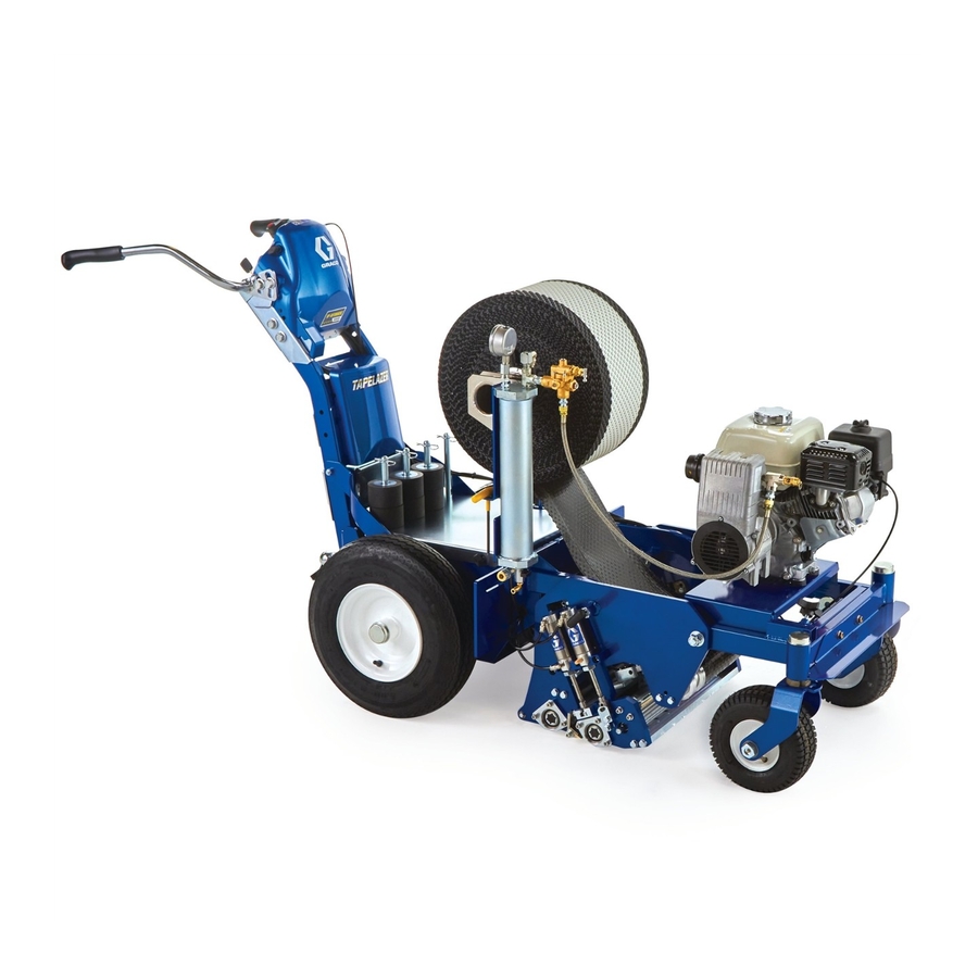
Page 6: Component Identification
Component Identification Component Identification Handlebar ™ LiveLook display Front wheel release lever Carriage raise/lower and engine stop Identification label USB charger/job logging download Tape application button Engine throttle Carriage Carriage locking pin LineDriver hitch Tape roll support spindle Parking brake Air drain valve Tape brake Cutting blade... -
Page 7: Setup/Startup
Setup/Startup Setup/Startup Pressure Relief Procedure Lock carriage in the up position by turning and pushing locking pins in on both sides of the carriage. This equipment stays pressurized until pressure is manually relieved. To help prevent serious injury from moving parts, follow the pressure relief procedure before cleaning, checking, or servicing the equipment. -
Page 8: Initial Setup
Setup/Startup Connecting a LineDriver Initial Setup It is recommended to use a LineDriver in conjunction with the TapeLazer. To connect the TapeLazer to a LineDriver, follow the steps below. To help prevent serious injury from Install LineDriver coupler to TapeLazer pinching or cutting, keep clear of the hitch ball. - Page 9 Setup/Startup Adjust LineDriver seat forward/backward with lever below seat. NOTE: To help reduce fatigue, adjust one pedal for a full motion forward and one for full motion in reverse. Loosen two bolts on topside of pedals on LineDriver. Rotate pedal on LineDriver to desired position.
-
Page 10: Tape And Roller Setup
Setup/Startup Tape and Roller Setup Re-install end collar. NOTE: It is critical that the tape remain in tension during the application process. Prior to locking the end collar into place, press the collar into the tape roll so that the tape does To help prevent injury from cutting, install not feed too fast during high speed the blade guard or remove blade prior to... -
Page 11: Roller Adjustment
Setup/Startup Roller Adjustment Feed tape through rollers as shown. To help prevent injury from cutting, install the blade guard or remove blade prior to adjusting rollers. Perform pressure relief procedure, see Pressure Relief Procedure, page 7. Using a 1/4 in. Allen wrench, adjust the tape collars on the guide roller to match the width and position of the tape. - Page 12 Setup/Startup Rotate pivot bar away from applicator Tighten set screws on roller segments roller. once in place and re-install bolt on end of hex shaft. Using a 1/4 in. Allen wrench, remove the three bolts holding the end plate on the Re-install applicator roller, plate and applicator roller.
- Page 13 Setup/Startup 11. Remove tamping roller and using a 1/4 12. Tighten set screws on all roller segments in. Allen wrench remove bolt on one end once in place and re-install bolt on the of the hex shaft. Loosen set screws in end of hex shaft.
-
Page 14: Blade Guard Removal And Installation
Setup/Startup Blade Guard Removal and Installation Tighten bolts. To help prevent injury from cutting, install the blade guard or remove blade prior to adjusting rollers. Perform pressure relief procedure, see Pressure Relief Procedure, page 7. Using a 1/4 in. Allen wrench, loosen bolts holding blade guard in place on both sides of the unit. - Page 15 Setup/Startup Using a 1/4 in. Allen wrench, tighten bolts. 3A8108A...
-
Page 16: Carriage Adjustment
Setup/Startup Carriage Adjustment Slide carriage left or right to the desired location. To help prevent serious injury from pinching or cutting, keep clear of the cutting blade and moving carriage parts. Often it is desirable to adjust the carriage to an offset position to accommodate curbs or difficult areas along the road edge. -
Page 17: Caster Wheel Adjustments
Setup/Startup Caster Wheel Adjustments Two front wheels allow the operator to lay If taper arcs to the left, loosen right set tape in straight lines. Over time, the unit may screw and tighten left set screw. become misaligned and will need to be adjusted. -
Page 18: Handlebar Adjustment
Setup/Startup Handlebar Adjustment The handlebar is adjustable, allowing users To adjust the height of handlebars use a to customize the height and tilt for 3/4 in. wrench to loosen the four bolts comfortable performance. To adjust (two on each side) holding the handlebar, follow the steps below: handlebars to the frame of the unit. -
Page 19: Engine Start
Setup/Startup Engine Start Perform Pressure Relief Procedure, Pull starter cord. page 7. Move fuel valve to open. After engine starts, move choke to open. Move choke to closed. Set throttle to desired setting. Set throttle to fast. Set engine switch to on. 3A8108A... -
Page 20: Initial Taping Setup
Setup/Startup Initial Taping Setup Time and Date, and The initial setup prepares the taper for operation based on a number of user entered Distance Units parameters. Language selections and the units of measure selections can be set before Press SETTINGS “B” from the SETUP/INFO you start, or changed later. -
Page 21: Calibration
Setup/Startup Calibration Press to select SETUP/INFO. Check rear tire pressure and fill to 55 +/- 5 psi (379 +/- 34 kpa), if necessary. Extend steel tape to 25 ft (8 m) or longer. Press for Calibration. Set TRAVEL DIST to 24 ft (7 m) or longer. Longer distances ensure better accuracy, depending on conditions. - Page 22 Setup/Startup Press and release tape application 10. Press and release tape application button to start calibration. button to complete calibration. NOTE: Calibration is NOT complete when Move TapeLazer forward. Keep guide on steel tape. the exclamation symbol is displayed. Stop when guide aligns with 25 ft mark NOTE: Calibration is finished when the check on steel tape (a total traveled distance of mark symbol...
-
Page 23: Operation
Operation Operation Modes of Operation • CUT DELAY – the end of each skip can be adjusted if necessary to correct for mechanical variations that cause a The method used to apply tape is set by the combination of the TAPE LINE TYPE setting discrepancy between the programmed and the MODE setting. -
Page 24: Tape Application Assembly Positions
Operation Tape Application Assembly Positions The Tape Application Assembly uses three In addition, the TapeLazer Carriage uses two positions during operation. These positions positions during operation, raised and may be relevant when operating, repairing, or lowered. These positions may be relevant assessing the TapeLazer. -
Page 25: Tapelazer Livelook Display
Operation TapeLazer LiveLook Display 3A8108A... -
Page 26: Applying Tape
Operation Applying Tape Start engine, see Engine Start, page 19. Press the carriage raise/lower and engine stop button to lower the carriage. Close air drain valve, as shown, to pressurize the system. Move forward and press tape application button to start applying tape. Unlock the locking pins on both sides of the carriage. -
Page 27: System Delay
Operation System Delay Choose Mode: Manual [M], Semi-Auto [S], or Auto [A]. System Delay (SD) improves tape Example below, when the pointer [A] placement accuracy by allowing the operator reaches start point [B] press (or hold in to look forward at the line guide mechanism, manual mode) the tape application important for maintaining straight lines. -
Page 28: System Delay Example - Semi-Auto Mode/Skip Line
Operation System Delay Example - Semi-Auto Mode/Skip Line [S] Semi-Auto Mode Skip Line placement using SD example shown: 1 ft intermittent skip, 72 inch System Delay. Tape Application Button Activity Press and RELEASE auto tape application button when pointer [A] reaches the beginning of each line [B]. -
Page 29: System Delay Example - Auto Mode/Skip Line
Operation System Delay Example - Auto Mode/Skip Line [A] Auto Mode Skip Line placement using SD example shown: 1 ft line, 2 ft space, 72 inch System Delay. Tape Application Button Activity Press and RELEASE tape application button when pointer [A] reaches start point [B]. Press and RELEASE tape application button a second time after pointer [A] passes ending line [D]. -
Page 30: System Delay Example - Manual Mode/Skip Line
Operation System Delay Example - Manual Mode/Skip Line [M] Manual Mode Skip Line placement using SD example shown: 1ft line, 2 ft space, 72 inch System Delay. Tape Application Button Activity Option 1 Press and HOLD tape application button when pointer [A] reaches start point [B]. -
Page 31: System Delay Example - Semi-Auto And Auto Mode/Solid Line
Operation System Delay Example - Semi-Auto and Auto Mode/Solid Line [S] Semi-Auto Mode and [A] Auto Mode Continuous Line placement using SD Example shown: 72 inch System Delay. Tape Application Button Activity NOTE: SEMI-AUTO MODE tape application button function for continuous line placement is identical to AUTO MODE. -
Page 32: System Delay Example - Manual Mode/Solid Line
Operation System Delay Example - Manual Mode/Solid Line [M] Manual Mode Continuous Line placement using SD Example shown: 72 inch System Delay. Tape Application Button activity Press and HOLD tape application button when pointer [A] reaches start of line [B]. Release tape application button at the end of the continuous line [D]. -
Page 33: Cut Delay
Operation Cut Delay If the skip line is longer or shorter than the displayed value follow the steps below. Cut Delay allows adjustment for correcting Negative Tape Cut Delay (-X) is used discrepancies between the actual tape length when actual tape length is longer than placed on the road versus the programmed programmed length. -
Page 34: Measure Mode
Operation Measure Mode Press and release tape application button. Move taper forwards or backwards. Measure Mode can be used in lieu of a tape measure to measure distances when laying NOTE: Moving backwards displays a out an area to be taped. negative distance. -
Page 35: Splicing Tape
Operation Splicing Tape Peel end of the tape from the new roll and match the ends of each tape roll. Apply splicing tape to tape seam. Halt TapeLazer before tape is finished to prevent tape from rolling off of the spindle and into the lower rollers. -
Page 36: Setup/Information
Operation Setup/Information Press to select Calibration. See Calibration, page 21. to select Setup/Information. Press to select Settings. See Universal Symbols Key, page 65, for explanation of screen symbols. See Settings, page 37. Press to select Information. See Information, page 38. Press to select Language. -
Page 37: Settings
Operation Settings Press to open Time an Date. Set Time an Date on this screen. This is to select Setup/Information. needed for accurate Data Logging. Press to open Settings Menu. Press to set Units as feet or meters. See Universal Symbols Key, page 65, for explanation of screen symbols. -
Page 38: Information
Operation Information Press to open Diagnostics. These screens are used to view and test to select Setup/Information. functionality of components. Press [C] to access information. Press to cycle forward to diagnostic See Universal Symbols Key, page 65, for explanation of screen symbols. screen #2 and screen #3, and to cycle back to diagnostic screen #1... -
Page 39: Data Logging
Operation Data Logging The TapeLazer control is equipped with Data Press the to open the Data Logging pop Logging, which allows the user to recall job data and export the data from the machine to up window. a USB drive. Choose to start recording a new job or view See Universal Symbols Key, page 65, for jobs previously done. -
Page 40: Maintenance
Maintenance Maintenance Periodic Maintenance Air Compressor DAILY: Check engine and compressor oil Before operation, ensure oil is visible on level and fill as necessary. threads of fill port. If not full, fill with oil until visible on threads. DAILY: Check hoses for wear and damage. NOTICE DAILY: Check pressure drain valve for Failure to properly fill compressor with oil... -
Page 41: Blade Replacement
Maintenance Blade Replacement Install new blade into place. To help prevent serious injury from cutting, wear gloves when handling the cutting blade. Perform pressure relief procedure, see Pressure Relief Procedure, page 7. Using a 1/4 in. Allen wrench, remove bolt holding blade in place from either side of the TapeLazer. -
Page 42: Brake Removal And Replacement
Maintenance Brake Removal and Replacement Pivot brake forward and remove. To help prevent injury, install the blade guard or remove blade prior to adjusting rollers. Perform pressure relief procedure, see Pressure Relief Procedure, page 7. Remove two pins holding brake in place. Set aside to reuse. -
Page 43: Troubleshooting
Troubleshooting Troubleshooting Follow Pressure Relief Procedure, page 7, before checking or repairing unit. Problem Cause Solution Engine won’t start. Engine switch is OFF. Turn engine switch ON. Engine is out of gas. Refill gas tank. Refer to Honda Engines Owner’s Manual. Engine oil level is low Try to start engine. - Page 44 Troubleshooting Problem Cause Solution Unit won’t activate (application roller will Tape line type not selected. Select “solid” or “skip” tape line type, see not drop down). Modes of Operation, page 23. Carriage is in the raised position. Lower carriage. See Tape Application Assembly Positions, page 24, for infor- mation on carriage positions.
- Page 45 Troubleshooting Problem Cause Solution Unit does not stabilize between 125 and Unloader valve is broken. Replace unloader valve. 145 psi. No battery voltage. Charging board is disconnected. Check charging board connection. If nec- essary, replace charging board. Will not actuate tape application assem- Control board output #1 is open.
- Page 46 Troubleshooting Solenoid Manifold Operation Operating Condition #1 To help prevent injury from moving parts, keep clear of carriage when actuating solenoid outputs. Perform Pressure Relief Procedure, page 7, before working on equipment. To diagnose a malfunctioning unit, begin with Tape application assembly is in cut position. diagnostics, see Information, page 38.
- Page 47 Troubleshooting Operating Condition #3 Notes: To energize solenoid outputs ‘1’ and ‘2’, press the tape application button once. To energize solenoid output ‘1’ by itself, press the tape application button twice. To energize solenoid output ‘C’, use the carriage raise/lower switch. To energize outputs ‘1’...
- Page 48 Troubleshooting Diagnosing a Short Circuit Without Solenoids Connected A short can be the result of two faulty 13.5 +/- 1 VDC 13.5 +/- 1 VDC 16-34 VDC components: faulty solenoid manifold or faulty control board. If control board voltages are in this range, the control board is good.
- Page 49 Troubleshooting To Check if Solenoids are Run unit to determine if the air compressor is outputting air. Open the Functioning Properly pressure relief valve to check for air flow. Run unit in diagnostics screen under the Also look for the compressor fan to be in following conditions, see Information, motion while the unit is running.
- Page 50 Troubleshooting Air Cylinder Internal Leaks Line Connection Sequence, page 63, when re-connecting air lines. If no airflow is observed, perform pressure relief procedure, see Pressure Relief Procedure, page 7. To help prevent injury from moving parts, keep clear of carriage when actuating Reconnect air lines disconnected in step solenoid outputs.
- Page 51 Troubleshooting Solenoid Ports Reference 3A8108A...
-
Page 52: Parts
Parts Parts TapeLazer Parts 3A8108A... - Page 53 20A435 GROMMET wash hd. 18C661 BOLT 16W408 KNOB, T-handle, 1/4-20 100214 WASHER 18C712 PLATE, cover, frame, rear 17K379 LABEL, Graco 17P925 LABEL, A+ service 18C730 LABEL, TapeLazer 15J088 SHEILD, distance sensor 17H742 LABEL, brand 15K452 SPACER, round 119569 BUSHING, strain relief...
- Page 54 Parts Front End Parts 3A8108A...
- Page 55 Parts Front End Parts List Ref. Part Description Qty. Ref. Part Description Qty. 113485 BEARING, cup/cone 101566 NUT, lock 18C620 FRAME, caster 111040 NUT, lock 113484 SEAL, grease 112405 NUT, lock 17H486 DISK, adjuster, assembly 112825 WASHER, Belleville 17H485 FORK, weldment 18C619 GUARD, frame, painted 113962...
- Page 56 Parts Carriage Applicator Parts 3A8108A...
- Page 57 Parts Carriage Applicator Parts List Ref. Part Description Qty. Ref. Part Description Qty. 18C583 BRACKET, cylinder rod 20A201 BRACKET, roller mount, support left 18C584 BRACKET, tape guides 20A203 BRACKET, roller mount, lead wire right 100057 SCREW, cap, hex hd. 18C582 BRACKET, roller mount, 20A653 BRACKET, lead in...
- Page 58 Parts Display Unit Parts 3A8108A...
- Page 59 Parts Display Unit Parts List Ref. Part Description Qty. Ref. Part Description Qty. 128783 SWITCH, rocker 17J125 BRACKET, slide 25A495 KIT, board, charger, 20A658 KIT, control, auto, battery, includes 62, TapeLazer 15K162 BLOCK, switch 17J136 SCREW, hex, flange hd. 194310 LEVER, actuator 17H720 STRAP, tie...
- Page 60 Parts Additional Parts 3A8108A...
- Page 61 Parts Additional Parts List Ref. Part Description Qty. Ref. Part Description Qty. 174 † 25R115 FILTER, air 111040 NUT, lock 175 † 25R114 BREATHER, oil 126596 SCREW, flange 19C950 KIT, compressor, includes 18C731 LABEL, brand, side 174, 175, 182a, 183, 283, 108851 WASHER, plain 177, 186...
-
Page 62: Air Line Schematic
Air Line Schematic Air Line Schematic 3A8108A... -
Page 63: Air Line Connection Sequence
Air Line Connection Sequence Air Line Connection Sequence When connecting air lines to solenoids they can often be difficult to lay into the unit. It is helpful to connect them in the order shown in the pictures below to avoid difficult connections later on. Connection order doesn’t matter for performance, only for the ease of the user. -
Page 64: Wiring Diagram
Wiring Diagram Wiring Diagram 3A8108A... -
Page 65: Universal Symbols Key
Universal Symbols Key Universal Symbols Key 3A8108A... -
Page 66: Technical Specifications
Technical Specifications Technical Specifications TapeLazer U.S. Metric Dimensions Height (with handlebar down) Unpackaged - 41 in. Unpackaged - 104 cm Packaged - 53 in. Packaged - 135 cm Width Unpackaged - 28 in. Unpackaged - 71 cm Packaged - 33 in. Packaged - 84 cm Length (with handlebar down) Unpackaged - 74 in. -
Page 67: Graco Standard Warranty
Graco’s written recommendations. This warranty does not cover, and Graco shall not be liable for general wear and tear, or any malfunction, damage or wear caused by faulty installation, misapplication, abrasion, corrosion, inadequate or improper maintenance, negligence, accident, tampering, or substitution of non-Graco component parts. - Page 68 All written and visual data contained in this document reflects the latest product information available at the time of publication. Graco reserves the right to make changes at any time without notice. Original instructions. This manual contains English. MM 3A8108...
Need help?
Do you have a question about the TapeLazer HP Automatic and is the answer not in the manual?
Questions and answers